

An end mill pulls out during steel roughing when the cutting force pulling the tool downward becomes stronger than the holder's grip. Start with the simple things: check the shank, collet, tightening torque, tool stick-out, runout and cutting load. Oil, chips, a worn collet, a long tool, full-width slotting, heavy corners and chatter can all cause trouble. If a tool starts at 70.00 mm and later measures 70.08 mm or 70.20 mm, stop and confirm whether it has actually moved before continuing the job.
Confirm That the Cutter Is Really Moving
One different tool-length reading is not enough to prove pull-out. Tool-setter repeatability, spindle temperature, dirt on the measuring surface and removing the holder can all change the reading slightly.
NIST recommends checking tool-setting repeatability by measuring the same stationary tool several times. One NIST procedure uses ten measurements with the spindle stopped to establish the normal measurement spread before machining.[1]
Use a simple check:
- Warm up the machine the same way you do for normal production.
- Clean the tool setter or measuring surface.
- Measure the installed cutter 5–10 times without cutting.
- Write down the highest and lowest readings.
- Draw a thin witness mark across the cutter shank and holder.
- Run a controlled roughing cut.
- Measure the tool again without removing the holder.
- Check whether the witness mark moved.
For example, suppose ten readings before cutting stay between 70.000 and 70.007 mm. That gives a normal spread of 0.007 mm. A single 70.010 mm reading after cutting is still close to that range. Readings of 70.045, 70.096 and 70.180 mm are different. At that point, especially if the witness mark has shifted, the cutter is clearly moving inside the holder.
Do not use 0.02 mm or 0.05 mm as a universal pull-out limit. Set your warning level above the normal measurement variation of your machine, but low enough to catch movement before it changes floor depth, remaining stock or holder clearance.
Check the Holder Before Changing the Program
A helical end mill does not only push sideways. It also creates an axial force along the cutter. During roughing, the holder has to resist both torque and the force trying to pull the cutter outward.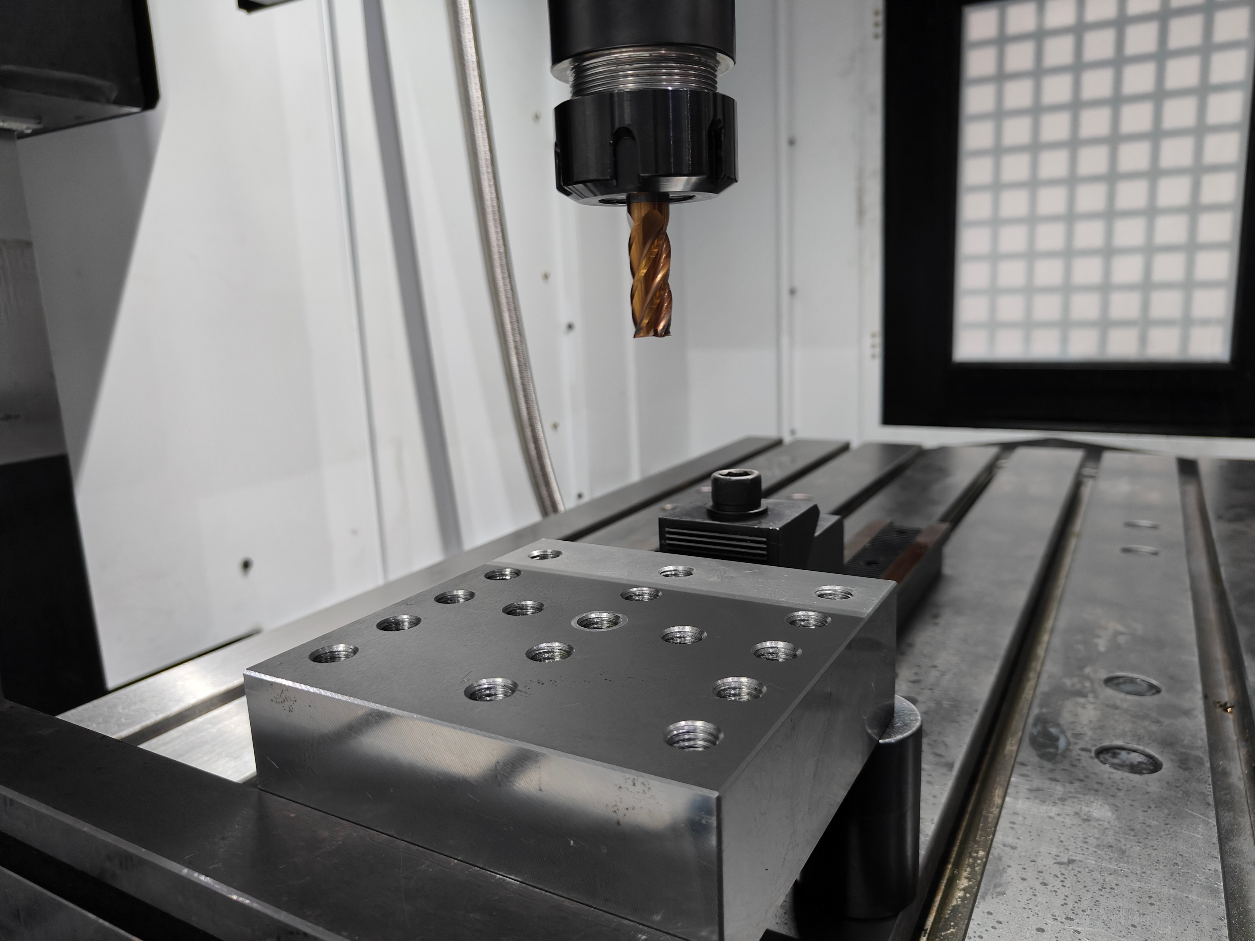
Check the basic setup first:
- the holder and collet match the cutter shank size;
- the correct nut is installed;
- the collet is properly clipped into the nut;
- enough straight shank sits inside the holder;
- the nut is tightened to the specified torque;
- the shank and gripping surfaces are clean;
- the collet, nut and holder are not visibly damaged.
ER collets, nuts and their main dimensions are covered by ISO 15488.[2] Actual grip still depends on the collet size, nut design, shank condition, tightening method and the condition of the holder.
Cutter design matters too. Two CNC cutting tools may both be 16 mm in diameter but have different helix angles, flute counts, rake geometry and cutting-edge lengths. Those differences change the load the holder has to handle.
Use the Correct Tightening Torque
An ER nut that is too loose may not grip the cutter firmly enough. Overtightening is not a good fix either. Too much torque can damage the collet, nut, threads or holder.
Use the torque specified for that exact holder and nut. Do not borrow a torque value from another ER size or another brand simply because the holders look similar.
A torque wrench also removes a lot of operator guesswork. If one operator always tightens to 90 N·m while another ends up anywhere between 65 and 105 N·m, those are not the same setup conditions.
Check whether the holder maker wants the threads dry or lubricated. Lubrication changes friction, so the same wrench setting can produce a different clamping force.
Keep Oil and Chips Out of the Gripping Area
If the holder relies on friction, keep the cutter shank, collet bore and holder bore clean unless the holder maker gives different instructions.
Inspect:
- the cutter shank;
- the inside of the collet;
- the holder bore;
- the collet slots;
- the reduction sleeve, if one is used;
- the nut contact surfaces.
A chip only a few tenths of a millimeter thick can stop a collet from seating evenly. Oil on the shank can also reduce or change the friction holding the cutter.
Do not treat the cutter shank and nut threads the same way. Some holders need lubricant on the threads or nut face while the cutter shank must stay clean and dry. Follow the holder manufacturer's instructions.
Replace Worn Collets
Look for polished bands, burrs, damaged slots, rust, cracks, trapped chips and uneven contact marks. A worn collet can still close around a cutter while gripping it unevenly.
If the same setup ran well for months and suddenly starts pulling tools out without a major program change, swap in a known-good collet early in the troubleshooting process.
When you can test safely, keep the cutter, holder, tool length and cutting data unchanged. Replace only the collet. If movement changes from 0.18 mm per test cycle to nothing beyond the normal measurement spread, the old collet is a strong suspect. If you change the cutter, collet, feed and toolpath together, you will not know which change fixed the problem.
Use Enough Straight Shank
Clamp the straight cylindrical section of the shank. Do not clamp on a flute, relieved neck or radius transition unless the cutter and holder were designed for it.
Pulling a cutter farther out to reach a deep pocket creates two problems:
- less straight shank may remain inside the holder;
- more cutter is left unsupported outside the holder.
Suppose you pull the cutter out another 25 mm to clear the part. If its original projection was 50 mm, the unsupported length has just increased by 50%.
Follow the holder manufacturer's minimum insertion requirement. ER, shrink-fit, hydraulic, milling-chuck and side-lock holders do not all use the same rule.
Keep Tool Stick-Out as Short as Possible
A long cutter acts like a longer lever. It bends more easily, and chatter can start sooner. NIST research on milling stability shows that tool overhang changes the dynamic behavior of the cutting system and changes the chatter-free operating range.[3]
It helps to record projection as an L/D ratio. For a 16 mm end mill:
| Stick-Out | L/D |
|---|---|
| 48 mm | 3D |
| 64 mm | 4D |
| 80 mm | 5D |
For a simple cantilever comparison, deflection increases roughly with the cube of unsupported length when the force, diameter and material stay the same.
Deflection ∝ L³
A 20% increase in unsupported length gives about 1.73 times the theoretical deflection:
1.2³ ≈ 1.73
Compare an 80 mm projection with a 48 mm projection:
(80 ÷ 48)³ ≈ 4.63
The real machine will also be affected by the spindle, holder, flute geometry and cutting force, but the comparison makes one thing clear: changing a 16 mm cutter from 3D to 5D projection is a substantial setup change.
Check Runout
Runout makes one flute take a heavier cut than the others. That uneven load can raise cutting force, vibration and tool wear. Research has also linked milling runout with changes in cutting force, tool life and machined surface condition.[4]
There is no useful single TIR limit for every cutter. Compare your reading with the cutter and holder specification and with known-good setups on the same machine.
For example:
- same cutter in Setup A: 0.006 mm TIR;
- same cutter in Setup B: 0.021 mm TIR.
That 0.015 mm difference is worth checking. Look for dirt, poor collet seating, a damaged collet, holder runout or a problem with the cutter shank.
Measure runout at the same point each time. A reading taken 5 mm from the holder nose cannot be compared directly with one taken 40 mm farther down the cutter.
Review Axial and Radial Engagement Together
Axial depth alone does not tell you how hard the cut is. Radial width alone does not either. Look at both along with chip load and cutter geometry.
For a 16 mm cutter:
| Radial Engagement | Width of Cut |
|---|---|
| 10%D | 1.6 mm |
| 25%D | 4.0 mm |
| 50%D | 8.0 mm |
| 100%D | 16.0 mm full slot |
Axial depth can be written the same way:
- 16 mm axial depth on a 16 mm cutter = 1D;
- 24 mm = 1.5D;
- 32 mm = 2D.
Before using a 32 mm axial depth, make sure the cutter actually has at least 32 mm of usable cutting edge and that the tool maker allows the cutting condition.
For mold steels such as P20 and H13, compare axial depth, radial width, feed per tooth and cutter type together when setting roughing parameters for P20 and H13 mold steel.
Check What Happens in Corners
A CAM program showing 25% radial engagement does not mean the cutter stays at 25% throughout the whole path.
Take a 16 mm cutter running along a wall with a normal 4 mm radial engagement:
- straight section: 4 mm = 25%D;
- heavier corner: 8 mm = 50%D;
- very heavy local engagement: 12 mm = 75%D;
- full slot: 16 mm = 100%D.
If the feed stays the same while engagement jumps from 4 mm to 12 mm, the cutter suddenly sees a much heavier cut.
If pull-out happens at roughly the same XY position on every part, open the stock simulation and inspect that exact area. Look for:
- a tight internal radius;
- rest material left by an earlier operation;
- a sudden step-down;
- an abrupt entry into uncut material;
- a short near-full-width cut.
A 35-minute roughing cycle can look fine for 34 minutes and 58 seconds, then hit one two-second section hard enough to move the cutter. Average spindle load may never show the real problem.
Full-Width Slots Need More Margin
A full-width slot engages the full cutter diameter. Compare a 16 mm cutter side milling at 4 mm radial width with the same cutter making a 16 mm slot:
- side milling: 4 mm = 25%D;
- full slotting: 16 mm = 100%D.
The slot also leaves less room for chips to escape. If chips stay trapped, the next flute can hit fresh steel and loose chips together.
If pull-out only appears during slotting, check:
- slot depth;
- feed per tooth;
- entry method;
- chip evacuation;
- tool projection;
- usable flute length;
- holder grip.
A ramp, pre-opened path or lower-radial-engagement strategy can avoid the sudden load of pushing directly into a long full-width slot.
Do Not Reduce Feed Blindly
A higher feed can raise cutting load, but slowing everything down is not always the answer. At low radial engagement, chip thinning can make the actual chip thinner than the programmed feed per tooth suggests.
Write down spindle speed, flute count and feed per tooth before changing anything.
For example:
- 3,000 rpm;
- 4 flutes;
- 0.06 mm/tooth.
The programmed feed is:
3,000 × 4 × 0.06 = 720 mm/min
Reduce feed per tooth to 0.04 mm while keeping the same rpm and flute count:
3,000 × 4 × 0.04 = 480 mm/min
You have cut the feed by one-third. That may reduce load, but it will not fix an oily shank, worn collet or one overloaded corner. If one small section of the toolpath is causing the problem, fix that section instead of slowing the entire roughing cycle.
When machining carbon or mold steel, match cutter geometry to the material and the engagement. This is also worth checking when selecting a cutting tool for carbon steel.
Watch for Chatter
Chatter makes the cutting force rise and fall instead of staying fairly steady. You can often hear or see it before you measure it.
Common signs include:
- regular wave marks on the cut surface;
- a strong high-pitched sound;
- rapid spindle-load changes;
- chipped cutting edges;
- one flute wearing much faster than the others.
NIST research shows that the dynamics of the tool-holder-spindle system affect milling stability and that tool-point behavior can change between setups.[5]
A first movement of 0.05 mm does not suddenly make a 60 or 80 mm tool much less rigid. The bigger concern is that the cutter is now cutting 0.05 mm deeper than programmed. If that movement grows to 0.30 or 0.50 mm, floor depth, axial engagement and stock left for the next operation can all change.
Use Spindle Speed to Control Chatter, Not Poor Clamping
Changing spindle speed can move the cut away from a chatter-prone range. It cannot remove oil from a shank, repair a worn collet or tighten a loose nut correctly.
Fix the holder setup first. If vibration remains, then test spindle-speed changes.
At high spindle speeds, stay within the rated limits of the cutter and holder. ISO 15641 covers safety requirements for milling cutters used in high-speed machining.[6]
Remove Chips From Deep Cuts
Chip evacuation often gets worse as the pocket gets deeper. Coolant that reaches the cutter easily near the top of a part may be blocked by the pocket wall farther down.
For example:
- at 20 mm pocket depth, coolant may still hit the cutting zone directly;
- at 60 mm, the walls may begin blocking the stream;
- at 100 mm, coolant may hit the holder or pocket wall instead of the cutter.
Those depths depend on the part geometry. Check where the coolant or air actually lands when the cutter reaches the deepest point of the operation.
Signs of poor chip evacuation include:
- small dark crushed chips;
- chips welded to the cutting edge;
- packed material in corners;
- large chip piles at the bottom of the cavity;
- sudden edge damage during deep passes.
Where the machine enclosure and shop rules allow it, a properly positioned CNC chip blower can clear areas that the normal coolant stream cannot reach.
Choose the Holder for the Cut
Keep the machine-side interface and cutter-clamping method separate in your diagnosis. BT40 and CAT40 describe how the holder connects to the spindle. ER, shrink fit, milling chuck and side lock describe how the cutter is held. If you are checking the spindle side, the differences between BT40 and CAT40 tool holders are relevant.
| Holder Type | Main Strength | Main Limitation | Typical Use |
|---|---|---|---|
| ER collet | Flexible and easy to use | Grip depends heavily on collet, nut and assembly condition | General milling and moderate roughing |
| Milling chuck | Strong grip and good rigidity | Larger body can limit access | Heavy roughing |
| Shrink fit | Good runout and slim shape | Standard versions still rely mainly on friction | Mold work and tighter cavities |
| Side lock | Good resistance to axial movement | Usually less concentric than precision friction holders | Heavy roughing with a proper flat |
| Mechanical anti-pullout | Positive axial locking | Requires matching tool and holder features | Repeated pull-out and high-load roughing |
Excellent runout does not guarantee the strongest pull-out resistance. Many precision holders still depend mainly on friction.
If the shank is clean, torque is correct, projection has been shortened and the toolpath no longer has a heavy engagement spike, but the cutter still moves, switch to a holder with stronger axial retention instead of tightening the existing holder harder.
Use the Correct Flat With a Side-Lock Holder
A side-lock holder should clamp against the cutter's proper flat. ISO 3338-2 specifies dimensions for flatted cylindrical milling-cutter shanks.[7]
Do not tighten the side-lock screw against a plain round carbide shank unless the tool and holder manufacturers allow it. The screw should sit on the intended flat, not on its edge.
Inspect the Cutter Shank After Pull-Out
Once you confirm that the cutter moved, inspect its shank before putting it into another precision holder.
Look for:
- polished rings;
- dark fretting marks;
- scratches;
- burrs;
- dents;
- rust;
- damage around a side-lock flat.
A polished band 10 or 15 mm wide may show where the cutter rubbed against the collet or holder bore while moving. If the shank looks damaged or undersize, measure it at several points with a micrometer instead of relying only on a caliper.
Some precision toolholding systems call for an h6 shank or another controlled shaft tolerance. ISO 286-2 provides standard tolerance classes and limit deviations for shafts and holes.[8]
Check the tolerance for the actual cutter diameter. The same micron value cannot be applied to every shank size.
Check the Spindle Side When Several Holders Have the Same Problem
If one cutter moves in one holder, start with that cutter and holder. If several known-good holders suddenly develop high runout, chatter or unstable tool position, the machine side deserves attention.
Check:
- the spindle taper;
- the holder taper;
- the pull stud;
- drawbar force;
- dirt between taper surfaces;
- fretting or crash marks.
Even a small chip on the spindle taper can tilt the whole holder. If several tools develop the same problem after a crash or maintenance job, inspect the common machine-side parts before replacing more collets.
Measure drawbar force with the proper equipment and compare it with the machine manufacturer's specification. You cannot judge drawbar force accurately by feel.
The LJ-855 vertical machining center, for example, uses a BT40 spindle interface, while BT40 holders can use several different cutter-clamping systems. Check cutter-to-holder movement and holder-to-spindle problems separately.
Change One Variable at a Time
Once the machine is safe to test, resist the temptation to change the collet, feed, rpm, tool projection and toolpath all at once. Make one change, run the same controlled test and measure the result.
Record at least:
| Item | Example Record |
|---|---|
| Tool diameter | 16 mm |
| Stick-out | 64 mm / 4D |
| Runout | 0.009 mm TIR |
| Spindle speed | 3,000 rpm |
| Feed per tooth | 0.06 mm/tooth |
| Programmed feed | 720 mm/min |
| Axial depth | 24 mm / 1.5D |
| Radial width | 4 mm / 25%D |
| Starting tool length | 82.000 mm |
| Ending tool length | 82.065 mm |
| Measured movement | +0.065 mm |
“Tool moved slightly” is hard to troubleshoot. “Tool moved +0.065 mm with 64 mm stick-out and 0.009 mm TIR” gives you something you can compare with the next test.
P20 Roughing Example
Consider a P20 roughing job using a 16 mm four-flute carbide end mill. The numbers below are a troubleshooting example, not cutting data for every P20 job. Actual settings still need to match steel hardness, cutter geometry, machine condition and the tool manufacturer's limits. The same variables are covered in this P20 mold steel machining guide.
| Variable | Initial Setup |
|---|---|
| Cutter | 16 mm, 4-flute carbide end mill |
| Holder | ER32 |
| Stick-out | 80 mm = 5D |
| Spindle speed | 3,000 rpm |
| Feed per tooth | 0.06 mm/tooth |
| Feed | 720 mm/min |
| Axial engagement | 28 mm = 1.75D |
| Normal radial engagement | 4 mm = 25%D |
| Initial runout | 0.018 mm TIR |
| Confirmed tool movement | +0.35 mm |
The cutter needs at least 28 mm of usable cutting edge for this example. Its 16 mm diameter alone does not tell you whether a 28 mm axial cut is suitable.
Inspection finds four problems:
- oil on the cutter shank;
- visible wear on the collet;
- 80 mm stick-out even though about 60 mm would clear the part;
- one corner where radial engagement rises well above the normal 4 mm.
The shop changes one item at a time.
Test 1: Clean the shank and holder, then tighten the nut to the specified torque. Keep the original collet, 80 mm stick-out and program unchanged.
Measured movement drops from 0.35 mm to 0.22 mm. Cleaning helped, but the cutter is still moving.
Test 2: Install a known-good collet. Leave the cleaned setup and cutting conditions unchanged.
Movement falls to 0.10 mm.
Test 3: Reduce projection from 80 mm to 60 mm. For the 16 mm cutter, that changes stick-out from 5D to 3.75D.
Movement falls again, this time to 0.045 mm.
Test 4: Change the overloaded corner so radial engagement no longer jumps far above the normal 25%D condition.
After three test cycles, the tool-length readings stay inside the measurement spread established before cutting.
The exact numbers will vary from one machine and holder to another. What matters is that each change was tested separately, so the shop could see how much each problem contributed.
Check in This Order
- Measure the same stationary tool several times and establish normal measurement variation.
- Use a witness mark to confirm movement inside the holder.
- Inspect the cutter shank.
- Clean the shank, collet and holder bore.
- Inspect the collet and nut.
- Confirm the specified tightening torque.
- Check that enough straight shank is engaged.
- Shorten unnecessary stick-out and record the new L/D.
- Measure runout at the same location each time.
- Find the exact toolpath position where movement starts.
- Check axial depth, radial engagement, slots and corners.
- Check for chatter and poor chip evacuation.
- Inspect the spindle interface if several holders show the same problem.
- Move to a higher-retention holder if the corrected setup still allows the cutter to move.
FAQ
How much pull-out is acceptable?
A cutter that is supposed to stay fixed should not keep creeping outward. First find the normal repeatability of your measuring system. If repeated static readings vary by only 0.006 mm but the tool grows by 0.05, 0.10 or 0.20 mm after cutting, investigate the movement before continuing production.
Can an ER holder rough steel?
Yes. ER holders are used for many steel roughing jobs. They work best when the shank is clean, the collet is in good condition, tightening torque is correct and tool projection is kept reasonable. Trouble becomes more likely when several demanding conditions appear together, such as 5D stick-out, full-width slotting, a worn collet and chatter.
Will more tightening torque stop pull-out?
Only when the holder was not tightened enough in the first place. Once you reach the manufacturer's specified torque, tightening harder is not a controlled solution. Check the shank, collet, insertion length, tool projection and cutting load instead.
Should I reduce the feed first?
Not by default. A four-flute cutter at 3,000 rpm and 0.06 mm/tooth runs at 720 mm/min. Dropping to 480 mm/min may reduce load, but it cannot fix an oily shank or worn collet. If the cutter only moves in one corner, correct that section of the toolpath instead of slowing the whole program.
Why does a long tool pull out more easily?
A longer projection bends more easily and is more likely to chatter. A 16 mm cutter at 48 mm projection is 3D. At 80 mm it is 5D. In a simplified bending comparison, the 80 mm unsupported section is about 4.6 times more flexible than the 48 mm section under the same force and section assumptions.
Can shrink fit still pull out?
Yes. Standard shrink-fit holders provide strong and even friction grip, but most still rely mainly on friction. If axial movement continues after you check the shank, holder condition, projection and toolpath, a positive-locking system can give you more resistance to pull-out.
When should I change holder type?
Change the holder when the cutter still moves after the gripping surfaces are clean, the collet and holder are undamaged, tightening torque is correct, projection is as short as practical, runout is under control and the high-load parts of the toolpath have been corrected.
Finally
Start with measurement, not a slower feed or extra torque. Confirm that the cutter is moving, then check the shank, collet, tightening torque, insertion length, runout and stick-out. After that, look at the actual cutting load, especially corners, full-width slots, chatter and deep-pocket chip evacuation. If the mechanical setup and toolpath are both under control and the cutter still creeps outward, the job needs a holder with stronger pull-out resistance.