

For most stable CNC turning and milling jobs, start with a coated carbide tool made for ISO P steel. Use high-speed steel for manual machines, low spindle speeds, repair work, small batches, taps, and reamers. If the steel is hardened above about 45 HRC, check whether a special carbide, ceramic, CBN tool, or grinding process is more suitable.
The correct tool depends on the steel grade, hardness, heat treatment, surface condition, operation, machine rigidity, and production quantity. Soft AISI 1018 steel often creates long chips and built-up edge. Heat-treated AISI 1045 steel creates higher cutting force and faster wear. Confirm these conditions before copying cutting data from another job.
Check the Steel Grade
“Carbon steel” covers many materials. The grade gives a useful starting point for estimating strength, hardness, chip shape, and tool wear.
| Steel group | Common examples | Main machining issue |
|---|---|---|
| Low-carbon steel | AISI 1010, 1018, 1020 | Long chips, built-up edge, and material sticking |
| Medium-carbon steel | AISI 1035, 1040, 1045 | Higher cutting force, heat, and flank wear |
| High-carbon steel | AISI 1060, 1075, 1095 | Faster abrasive wear, especially after heat treatment |
| Free-machining carbon steel | Grades containing machinability additives | Usually easier chip breaking, but properties vary by grade |
Low-carbon steel commonly contains up to about 0.30% carbon. It is relatively soft and ductile. Its main machining problem is often not hardness but long chips and material welding to the cutting edge.
Medium-carbon steel commonly contains about 0.30% to 0.60% carbon. It is stronger and may be supplied in annealed, normalized, or quenched-and-tempered condition.
High-carbon steel commonly contains more than about 0.60% carbon. It can become much harder after heat treatment and may need lower cutting speed, a stronger edge, and better wear resistance.
AISI 1045, C45, S45C, and EN8 are commonly used for shafts, pins, gears, fixtures, and general machine parts. The ASIATOOLS 1045, C45, S45C, and EN8 material page provides more information about available forms, properties, and machining services.
Ask the material supplier for:
- The exact AISI, SAE, EN, JIS, or GB grade
- Hardness in HB, HRC, or HV
- Heat-treatment condition
- Hot-rolled, cold-drawn, forged, or other delivery condition
- Tensile strength when hardness is not available
- A material certificate for production parts
If you are ordering cut-to-size blanks, review the grade, dimensions, tolerance, surface condition, inspection documents, and machining allowance together. The ASIATOOLS steel solutions page shows the information that can be confirmed before ordering.
Check Hardness
Heat treatment can affect tool choice more than the steel grade name. Annealed 1045 steel and hardened 1045 steel may need completely different cutting tools and speeds.
| Reported hardness | Typical condition | Starting tool choice |
|---|---|---|
| Below about 220 HB | Soft, annealed, or normalized steel | HSS for manual work; coated carbide for stable CNC production |
| About 220–320 HB | Stronger or pre-hardened steel | Coated carbide is normally preferred |
| About 35–45 HRC | Harder heat-treated steel | Heat-resistant carbide with controlled cutting data |
| Above about 45 HRC | Hardened steel | Special carbide, ceramic, CBN, or grinding may be considered |
| About 55–65 HRC | Common hard-turning range | CBN is widely used for stable finishing |
These ranges are starting points, not fixed limits. HB and HRC are different hardness scales. Do not compare their numbers directly without a conversion table, and treat converted values as approximate.
Some shafts have only a hardened outer layer. An induction-hardened shaft may have a hard surface and a softer center. Cutting force and chip shape can change when the tool passes through the hard layer.
For a surface-hardened part, confirm the surface hardness, hard-layer depth, core hardness, and whether the planned cut stays inside the hardened layer.
Check the Surface
Hot-rolled steel: Oxide scale can cause notch wear and small edge chips. Use a stronger edge and enough depth of cut to get below the scale when the setup allows it.
Cold-drawn steel: The surface is normally cleaner, but residual stress may cause long or thin parts to bend after material is removed. Rough both sides in a balanced order and leave enough stock for finishing.
Forged steel: Forgings may have scale, uneven stock, soft areas, and local hard spots. Begin with a tough grade and a lower cutting speed than you would use on clean bar stock.
Flame-cut steel: Remove loose slag before machining. Avoid a very shallow first pass that only rubs across the heat-affected surface.
Welded parts: The tool may pass through base steel, weld metal, and a heat-affected zone. This creates changing cutting forces and may require a tougher edge.
For a practical workpiece-preparation process, see How to Prepare Steel Blocks Before CNC Machining.
Handle Unknown Steel Carefully
Do not start an unknown steel part at an aggressive cutting speed.
- Inspect the part for scale, welds, flame-cut edges, and hardened surfaces.
- Measure hardness at several positions.
- Check whether the surface is harder than the inside.
- Use a tough general-purpose tool.
- Start near the lower end of the tool maker's cutting range.
- Make a short trial cut.
- Inspect the chips and cutting edge before increasing speed.
A spark test may help separate broad steel groups, but it cannot confirm an exact grade. Color, magnetism, and weight also cannot identify a specific carbon steel.
Define the Operation
| Cutting condition | What the tool needs |
|---|---|
| Continuous cutting | Good wear and heat resistance |
| Interrupted cutting | More toughness and a stronger edge |
| Roughing | Strong edge, chip space, and high load capacity |
| Finishing | Sharp edge, low runout, and controlled cutting force |
| Deep holes or slots | Reliable chip evacuation |
| Thin or flexible parts | Positive geometry and low cutting force |
Keyways, cross holes, splines, hexagonal stock, rough forgings, and welds create interrupted cuts. Start with a lower speed than for a smooth continuous cut and inspect the edge for random chipping.
Choose the Tool Material
| Tool material | Best use | Main limit |
|---|---|---|
| High-speed steel | Manual machines, low speed, repair work, taps, and reamers | Runs much slower than carbide |
| Cobalt HSS | Drilling and tapping medium-carbon steel | Still sensitive to overheating and poor chip removal |
| Powder-metal HSS | High-quality taps, form tools, broaches, and interrupted work | Costs more than standard HSS |
| Coated carbide | Most stable CNC turning, milling, and drilling work | Can chip under vibration or impact |
| Cermet | Stable finishing of low-carbon and other ferrous steels | Lower resistance to impact and thermal shock |
| Ceramic or CBN | Hardened steel and stable hard finishing | Needs a rigid machine and correct application |
Coated carbide is normally the first choice for production CNC work because it provides a useful balance of speed, wear resistance, and toughness.
The ASIATOOLS CNC cutting tools page shows an example of an indexable insert and the basic information that should be checked, including workpiece material, insert type, shape, size, and coating.
Choose the Tool Construction
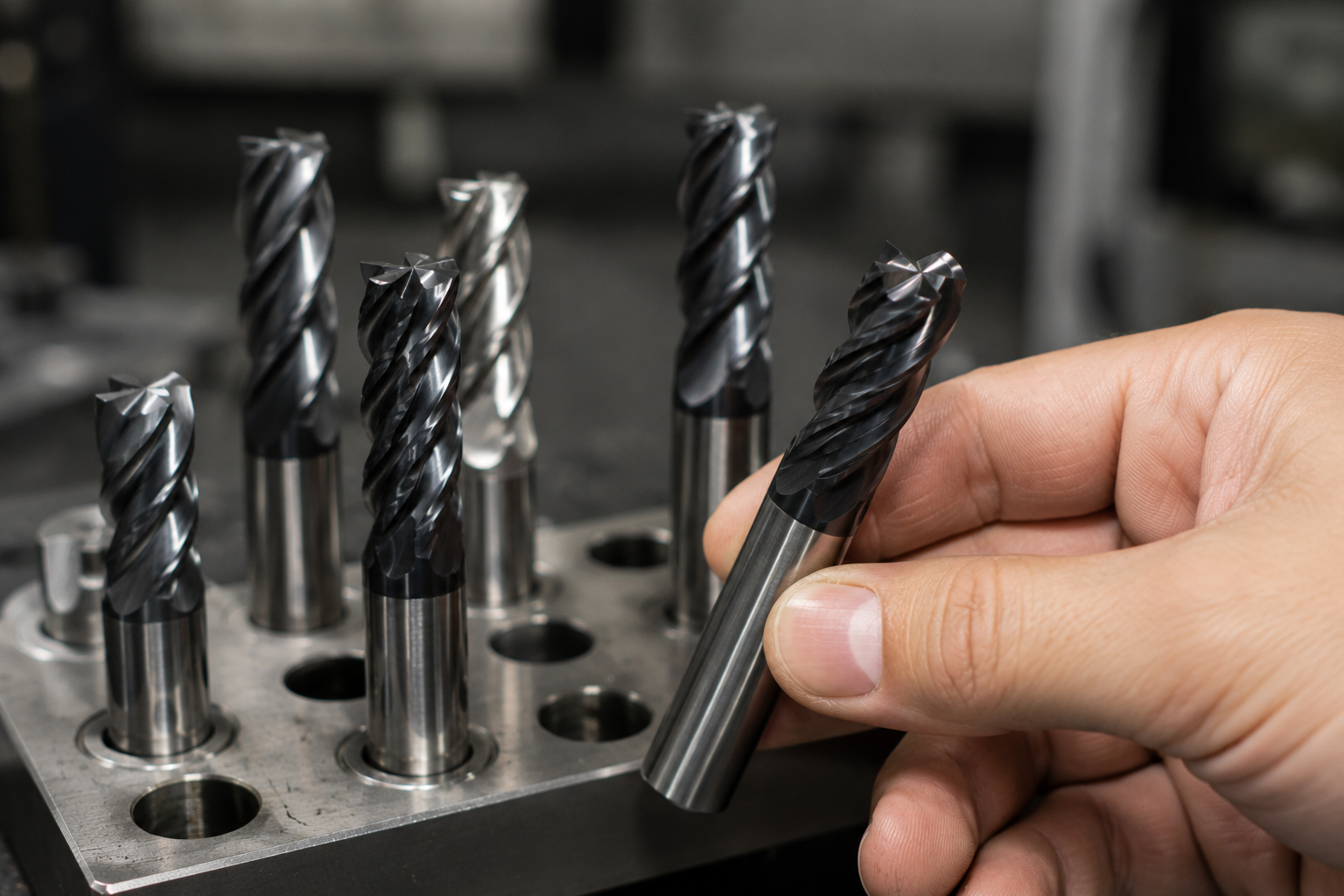
Solid carbide tools are common for small drills, end mills, pockets, profiles, and accurate holes. They are rigid and precise but need low runout and stable clamping.
Indexable tools use replaceable inserts. They are common in turning, boring, face milling, and large-hole drilling. Only the insert is replaced when an edge wears out.
Brazed carbide tools can be useful for special profiles and low-volume work. They can be resharpened, but poor grinding can change the cutting angle or weaken the edge.
Keep indexable insert pockets clean. A small chip under the insert can change its position, damage the pocket, and cause incorrect dimensions.
Choose the Carbide Grade
Carbide grades trade toughness against wear resistance.
| Condition | Grade direction |
|---|---|
| Cross holes, keyways, scale, vibration, or heavy roughing | Choose more toughness |
| Continuous cuts, stable clamping, and long production runs | Choose more wear resistance |
| ISO P area | General use |
|---|---|
| Lower P range | Stable finishing and continuous cutting |
| Middle P range | General steel machining |
| Higher P range | Roughing, interrupted cuts, and less stable conditions |
ISO P numbers are application ranges, not a universal hardness scale. A P25 grade from one manufacturer may use a different carbide base, coating, and edge treatment from a P25 grade made by another company.
Choose the Edge Geometry
Positive geometry cuts with lower force. It is useful for soft steel, thin walls, long shafts, boring, small machines, and finishing.
Negative geometry provides a stronger edge and often more usable cutting sides. It is common for roughing on rigid CNC lathes.
A sharp edge lowers cutting force and helps reduce material sticking in soft steel.
A honed or chamfered edge is stronger and better suited to scale, harder steel, high feed, and interrupted cuts.
| Turning insert nose radius | Common direction |
|---|---|
| 0.2–0.4 mm | Light finishing, boring, and flexible parts |
| 0.8 mm | General turning |
| 1.2 mm or larger | Rigid roughing and higher feed |
These are common starting directions, not fixed limits. A larger nose radius strengthens the edge but increases radial force. It can cause chatter on a long shaft or thin wall.
Match the Chipbreaker
| Condition | Likely result |
|---|---|
| Feed too low | Long chips, rubbing, and built-up edge |
| Feed too high | High cutting force, chipping, and rough feed marks |
| Depth too small | The chip may remain near the nose and miss the chipbreaker |
| Chipbreaker too light | Poor control during roughing |
| Chipbreaker too heavy | Rubbing and poor control during a light finishing cut |
Before changing inserts, check whether the programmed feed and depth are inside the recommended chipbreaker range.
Choose the Coating
| Coating | Common use |
|---|---|
| TiN | General-purpose drills, taps, and lower-cost tools |
| TiCN | Improved wear resistance at moderate cutting temperatures |
| TiAlN or AlTiN | Higher-temperature carbide drilling and milling |
| Aluminum-oxide CVD layers | Heat and crater-wear protection in steel turning |
| PVD coating | Thin coating used on relatively sharp and tough edges |
| CVD coating | Strong wear and heat protection in many turning applications |
Do not select a tool by coating color alone. The carbide base, edge preparation, coating structure, and chipbreaker all affect performance.
Choose a Turning Tool
For ordinary CNC turning of annealed or normalized carbon steel, start with a coated ISO P carbide insert and a medium chipbreaker.
CNMG and WNMG inserts are common for general roughing because they provide strong cutting edges and several usable sides.
CCMT and DCMT positive inserts are useful for smaller machines, boring, flexible parts, and lower cutting force.
DNMG and VNMG inserts provide better access near shoulders and profiles. Their narrower tips are not as strong as a larger-angle roughing insert.
For soft 1018 steel, use a sharp edge and enough feed to activate the chipbreaker. If the finish changes quickly, inspect the edge for built-up material before changing to a harder carbide grade.
For heat-treated 1045 steel, confirm hardness first. A smooth continuous cut may use a wear-resistant grade, while a shaft with cross holes needs more toughness. See Optimize S45C Steel Machining: Tips for Tool Life and Efficiency for more detail on this material family.
A wiper insert can produce a better finish at a higher feed, but it needs correct tool alignment and a stable part. It will not fix chatter or workpiece bending.
Choose a Milling Tool
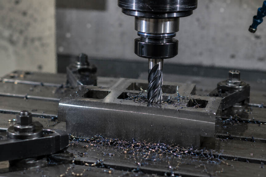
Use an indexable face mill for large flat surfaces and a solid carbide end mill for slots, pockets, and profiles.
A 45-degree face mill produces a balanced combination of radial and axial cutting forces. It is a common first choice for general face milling.
If the target chip thickness is 0.10 mm, a 45-degree cutter may need about 0.14 mm per tooth to produce that chip thickness. This is a geometry example, not a universal feed recommendation.
A 90-degree cutter produces mainly radial force and relatively little axial pressure. It is required for square shoulders and can help on parts that cannot accept high force toward the table. The radial force may still bend a thin vertical wall.
Use fewer flutes for full-width slots, deep pockets, and restricted chip space. Use more flutes for light radial engagement, wall finishing, and operations where chips can leave easily.
Full-slot milling creates more tool load and less chip space than side milling. With a 20 mm end mill cutting at 2 mm radial engagement, only 10% of the cutter diameter is engaged. Chip thinning may require a higher programmed feed than the target chip thickness, but the exact value must come from the tool maker's data.
A machining center must provide enough spindle speed, power, travel, and tool capacity. The ASIATOOLS LJ-855 vertical machining center, for example, is designed for milling, drilling, boring, tapping, and thread milling in one setup.
Choose a Drill
Use an HSS drill for manual drilling, occasional holes, repair work, and machines with limited spindle speed.
Use a cobalt HSS drill when ordinary HSS loses hardness too quickly. Cobalt drills are common for medium-carbon steel, but they still need the correct speed, feed, and cutting fluid.
Use a solid carbide drill for stable CNC production, higher hole quantities, shorter cycle times, and more consistent hole size.
A 118-degree point is a common general-purpose drill design. A 135-degree split point can reduce wandering and center thrust on a flat surface, but it is not automatically better for every hole.
A drill entering a curved or angled surface receives uneven force. Possible solutions include machining a flat first, using a shorter drill, reducing entry feed, or selecting a drill made for angled entry.
| Drill diameter | Hole depth | Depth ratio |
|---|---|---|
| 10 mm | 30 mm | 3×D |
| 10 mm | 50 mm | 5×D |
| 10 mm | 80 mm | 8×D |
As hole depth increases, internal coolant, flute space, runout, and chip shape become more important.
As one manufacturer reference, keeping cutting-edge runout at or below about 20 μm is useful for many symmetrical solid-carbide and exchangeable-tip drills. Small or high-precision tools may require a lower value, so follow the selected drill's limit.
Drilling alone may not meet a tight hole tolerance. A precision hole may need drilling followed by reaming, boring, finish boring, or honing.
Choose a Tap
Use a spiral-point tap for many through holes because it pushes chips forward.
Use a spiral-flute tap for many blind holes because it pulls chips back toward the hole entrance.
A blind hole must be deeper than the required full thread. Extra depth is needed for the tap chamfer, incomplete thread, chips, and clearance above the bottom.
A forming tap moves the steel instead of cutting it. It creates no chips but needs:
- A larger prepared hole than a cutting tap
- Tight control of hole diameter
- A ductile material condition
- Good lubrication
- Enough machine torque
A bottom hole that is too small increases torque and can break the tap. A hole that is too large reduces thread engagement. Use the tap manufacturer's recommended drill size.
Consider Thread Milling
Thread milling is useful for large threads, blind holes, expensive parts, adjustable thread size, and jobs where removing a broken tap would be difficult.
It normally produces smaller chips and lower cutting force than tapping, but it requires CNC interpolation and correct programming.
For small common threads in high-volume production, tapping may still be faster.
Choose a Saw Blade
Bi-metal band-saw blades are suitable for general carbon-steel bars, tubes, and structural sections.
Use a coarser tooth pitch for thick solid material and a finer pitch for thin-wall material.
Too few teeth in the cut may strip teeth from the blade. Too many teeth can fill the gullets, trap chips, and create excess heat.
A variable-pitch blade is useful for tubes, angle steel, channel sections, and mixed stock sizes.
Follow the blade maker's break-in procedure. Applying full feed to a new blade can damage the fresh tooth tips.
For production plate cutting, a carbide circular saw may provide faster and more controlled cutting when the machine and blade match the steel. The ASIATOOLS PCS-800NC flat-plate circular saw is designed for plate and structural-steel cutting.
Calculate Spindle Speed
Metric RPM = Cutting speed in m/min × 1,000 ÷ (π × diameter in mm)
Imperial RPM ≈ Cutting speed in SFM × 3.82 ÷ diameter in inches
Example: a 12 mm drill has a sample cutting speed of 120 m/min.
RPM = 120 × 1,000 ÷ (3.1416 × 12) ≈ 3,180 RPM
Example: a 50 mm workpiece is turned at a sample cutting speed of 180 m/min.
RPM = 180 × 1,000 ÷ (3.1416 × 50) ≈ 1,146 RPM
These are calculation examples, not universal cutting recommendations. Use the speed range supplied for the exact tool.
When using constant surface speed on a CNC lathe, enter a safe maximum RPM so the spindle does not accelerate too far as the cutting diameter becomes smaller.
Set Feed and Depth
Milling table feed = Feed per tooth × Number of effective teeth × RPM
Example: a four-flute end mill runs at 4,000 RPM with a sample feed of 0.05 mm per tooth.
Table feed = 0.05 × 4 × 4,000 = 800 mm/min
A cutting edge has a small edge radius. If the feed is too low, the edge may push and rub the steel instead of forming a proper chip. This increases heat, built-up edge, and flank wear.
In turning, use enough depth to cut below scale or a work-hardened surface when the setup allows it.
In milling, separate axial depth from radial width:
- Axial depth: how far the cutter enters along its axis
- Radial width: how much of the cutter diameter contacts the workpiece
Machining allowance also depends on steel size, heat treatment, stress, flatness, and roughing sequence. See How Much Allowance Should 1045 Steel Blocks Keep Before CNC Milling? for more detail.
Use Coolant Correctly
Coolant can reduce friction, control temperature, and move chips away from the edge.
- Check coolant concentration.
- Confirm that the nozzle reaches the cutting zone.
- Maintain enough flow to move drilling chips.
- Keep the filter and tank clean.
- Follow the tool maker's wet or dry cutting recommendation.
Repeated heating and cooling may cause thermal cracks in some milling inserts. Inconsistent coolant can be worse than stable wet or dry cutting.
Read the Chips and Tool Wear
| What you see | Likely cause | What to check |
|---|---|---|
| Long ribbon chips | Soft steel, low feed, small depth, or wrong chipbreaker | Feed, depth, geometry, and chipbreaker range |
| Built-up edge | Low speed, blunt edge, or poor lubrication | Edge sharpness, speed, and coolant |
| Even flank wear | Normal wear or speed that is too high | Planned wear limit and cutting speed |
| Random chipping | Impact, vibration, loose clamping, or weak edge | Setup, interruption, holder, and carbide toughness |
| Notch wear | Scale, hard surface, or repeated depth line | Surface condition, depth, and edge strength |
| Thermal cracks | Repeated heating and cooling | Coolant use, milling grade, and cutting speed |
| Uneven flute wear | Tool runout | Spindle, holder, collet, and tool seating |
| Damaged drilling chips | Chip packing or poor coolant flow | Flutes, coolant, hole depth, and feed |
Blue chips do not automatically mean the speed is wrong. During carbide cutting, heat can leave with the chip. Investigate when blue chips appear with edge deformation, fast coating loss, size drift, or toolholder overheating.
Fix Surface Problems
| Problem | Common causes |
|---|---|
| Rough surface | Built-up edge, worn tool, high feed, vibration, or part bending |
| Chatter marks | Long overhang, weak support, loose clamping, or unsuitable spindle speed |
| Size drift | Tool wear, part heating, insert movement, or incorrect compensation |
| Heavy burrs | Dull edge, unsupported drill exit, or unsuitable cutting direction |
Inspect the cutting edge before changing carbide grade. A small built-up edge can damage the surface even when the insert itself is not badly worn.
Check the Setup
- Keep tool and workpiece overhang as short as possible.
- Check chuck pressure and fixture contact.
- Clean the insert pocket.
- Inspect the collet and toolholder for wear.
- Measure spindle and tool runout with an indicator.
- Check tailstock alignment on long shafts.
- Aim the coolant nozzle at the cutting zone.
For repeated plate and block machining, consistent workholding reduces setup variation. The ASIATOOLS hydraulic clamping system is an example of a fixture system designed for repeatable CNC clamping.
Run a Trial Cut
| Trial item | Practical starting point |
|---|---|
| First parts inspected | 3–5 parts |
| Suggested wear checks | After 5, 10, 20, and 40 parts |
| Variables changed at one time | One |
| Dimensions recorded | First, middle, and final part in the trial |
| Tool replacement | Before random chipping or size failure |
Also record the tool model, steel grade, hardness, speed, feed, depth, coolant method, parts per edge, and reason for replacement.
Compare Cost per Part
Tool cost per part = Cost per cutting edge ÷ Acceptable parts per edge
Example: an insert costs $12 and has four usable edges. Each edge costs $3. If one edge produces 60 acceptable parts, the direct insert cost is $0.05 per part.
A second insert costs $20 and also has four edges. Each edge costs $5. If one edge produces 160 acceptable parts, its direct insert cost is about $0.031 per part.
| Tool | Average life | Typical variation |
|---|---|---|
| Tool A | 80 parts | 75–85 parts |
| Tool B | 100 parts | 30–150 parts |
Tool A may be safer for expensive parts or unattended machining because its life is more predictable, even though Tool B has a higher average.
Also include tool-change time, machine downtime, tool setting, cycle time, scrap, rework, and unplanned edge failure.
Avoid Common Mistakes
- Choosing a tool without checking steel hardness
- Using a finishing chipbreaker for heavy roughing
- Running carbide at HSS cutting speed
- Running HSS at carbide cutting speed
- Choosing a brittle grade for a severe interrupted cut
- Ignoring chips under an indexable insert
- Using a worn collet or damaged holder
- Copying RPM from a different tool diameter
- Changing speed, feed, depth, and tool grade at the same time
- Continuing production after random edge chipping begins
Work Safely
- Close machine guards and CNC doors before cutting.
- Clamp the workpiece before drilling or milling.
- Wear suitable eye protection.
- Keep loose clothing, hair, and loose gloves away from rotating parts.
- Remove the chuck key before starting the spindle.
- Stop the spindle before removing chips.
- Use pliers or a chip hook instead of your hands.
- Protect long bar stock extending from the rear of a spindle.
- Lock out the machine before maintenance.
See the OSHA machine-guarding requirements for general workplace guidance.
Selection Checklist
- Steel grade and equivalent standard
- Hardness and heat-treatment condition
- Surface and delivery condition
- Turning, milling, drilling, tapping, or sawing
- Roughing or finishing
- Continuous or interrupted cutting
- Depth and width of cut
- Machine power and spindle-speed range
- Toolholder type and tool overhang
- Coolant method
- Required tolerance and surface finish
- Production quantity and target cycle time
- Current tool life and wear pattern
Conclusion
For stable CNC machining below about 220 HB, coated ISO P carbide is usually the best starting point; HSS and cobalt HSS remain practical for manual machines, small batches, taps, and reamers. Between about 35 and 45 HRC, use a heat-resistant carbide grade and conservative cutting data. Above 45 HRC, compare special carbide, ceramic, CBN, and grinding; CBN is most common in stable finishing around 55–65 HRC. Keep drill runout within the tool maker's limit, inspect the first 3–5 parts, and judge the result by controlled chips, gradual wear, stable size, and cost per acceptable part.