

Uneven chamfer width is prevented by controlling the block position, clamping, cutter runout, tool bending, toolpath speed, and measurement method. Measure several points along the same edge first. If the whole chamfer is equally too wide or too narrow, check the cutting depth and offset. If the width changes along the edge, remove the source of variation before changing the offset.
This guide covers straight outside chamfers on rectangular mold steel blocks. The same checks apply whether the work is done on a machining center or a dedicated CNC edge chamfering machine.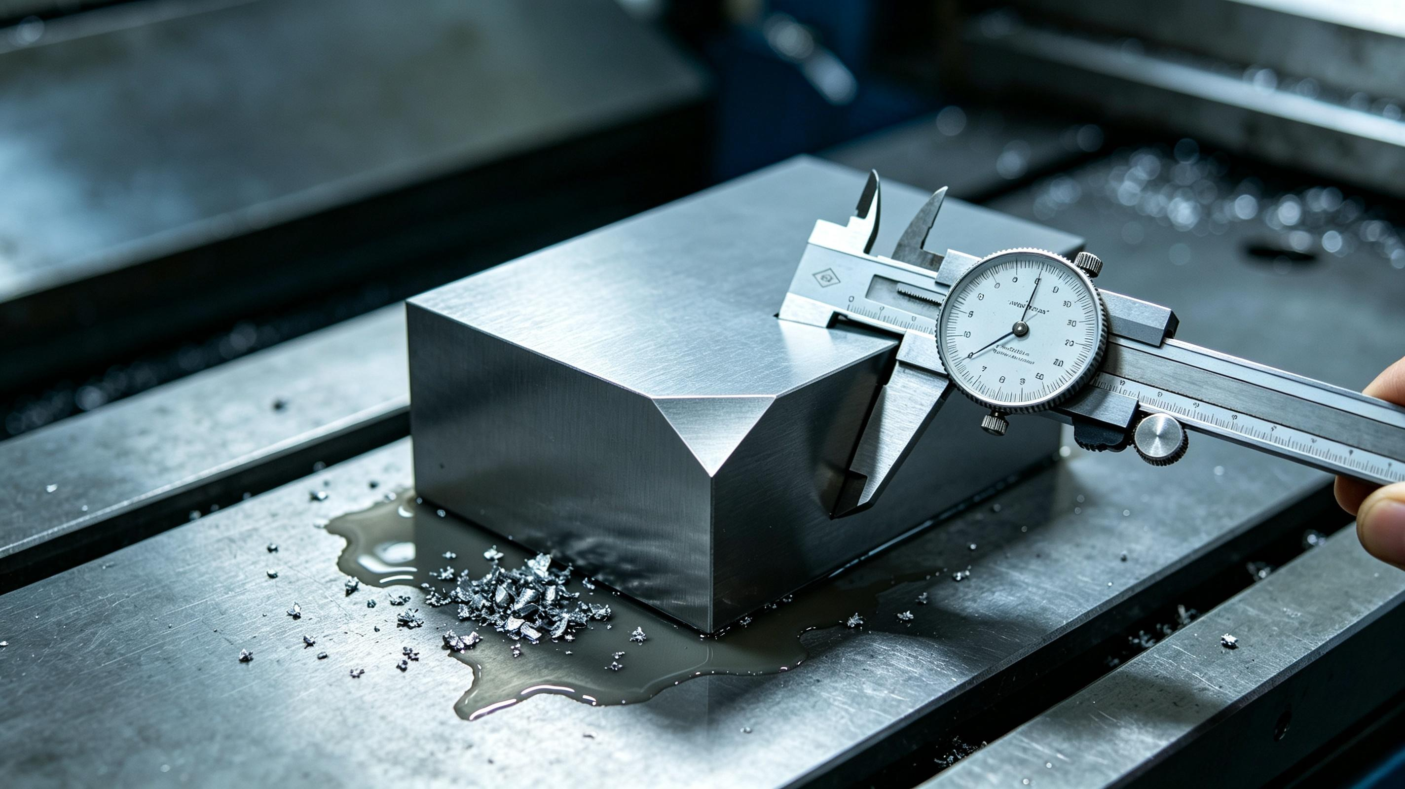
Define the Chamfer
Confirm what the drawing requires before changing the program. A chamfer may be shown as C0.5, C1.0, 1 × 45°, 2 × 30°, or as a separate face-width dimension.
Do not assume C1.0 always means the same thing. The drawing standard and inspection rule should state whether the controlled dimension is:
- The distance removed from the top face.
- The distance removed from the side face.
- The width measured along the sloped face.
For a 45-degree chamfer between two square faces, the top and side distances are equal. If both distances are 1.00 mm, the sloped face is:
Chamfer-face width = 1.00 × √2 = approximately 1.414 mm
This calculation applies only when the two original faces are square, the angle is 45 degrees, and the original edge is treated as a sharp intersection.
For another chamfer angle:
Horizontal distance = vertical cutting depth ÷ tan θ
Here, θ is the angle between the chamfer and the top surface.
45-Degree Position Error Example
The following values are calculated examples, not universal tolerances.
| Vertical Position Change | Change in Chamfer Leg | Change in Sloped Face Width |
|---|---|---|
| 0.02 mm | 0.02 mm | 0.028 mm |
| 0.05 mm | 0.05 mm | 0.071 mm |
| 0.10 mm | 0.10 mm | 0.141 mm |
Also check how the cutter angle is named. A symmetrical 90-degree chamfer cutter normally has two sides at 45 degrees to the tool axis and is used to cut a 45-degree chamfer.
The inspection instruction should state the dimension and angle, tolerance, measurement positions, corner rule, measuring tool, and burr-removal condition.
An edge rounded during grinding, heat treatment, polishing, or hand deburring can make the chamfer boundary hard to see. Depending on the measuring method, the chamfer may appear wider or narrower even when the cutter position has not changed.
Measure the Width Pattern
Do not judge a long chamfer from one measurement. Use the same positions on every part:
- 15 mm from the start of the straight edge.
- 25% of the edge length.
- 50% of the edge length.
- 75% of the edge length.
- 15 mm from the end.
Measure corners separately. A corner can be wider because the machine slows down or two toolpaths overlap, even when the straight section is correct.
Example of a Tapered Chamfer
| Measurement Position | Chamfer Width |
|---|---|
| 15 mm from start | 0.94 mm |
| 25% | 0.97 mm |
| 50% | 1.01 mm |
| 75% | 1.06 mm |
| 15 mm from end | 1.10 mm |
The edge changes by 0.16 mm from one end to the other. This is not a simple offset error. Check the block, supports, clamping, fixture, and machine alignment.
Example of a Wide Corner
| Location | Chamfer Width |
|---|---|
| Straight-edge average | 1.01 mm |
| 10 mm before corner | 1.02 mm |
| Corner | 1.16 mm |
| 10 mm after corner | 1.04 mm |
The corner is 0.15 mm wider than the straight-edge average. Check corner speed, overlap, lead moves, and exact-stop behavior instead of changing the complete Z offset.
Rotate a Test Block
Use this test only on a safe, symmetrical test block. Rotate the block 180 degrees, set the work offset again, and machine the same type of edge through the same machine area.
- If the wide end follows the same physical end of the block, check the block shape or local material condition.
- If the wide area stays at the same fixture or machine position, check the supports, fixture level, spindle angle, and machine movement.
Do not rotate a production part and run the old program without checking position, clearance, work offset, and clamping.
Reverse the Cutting Direction
Reversing the toolpath can help identify cutting-force or entry problems. Keep the start position, lead-in length, finishing stock, machine area, and compensation method as similar as possible.
Change One Part at a Time
When checking the cutter and holder, do not replace both at once. Test the original cutter in another verified holder, then test a verified cutter in the original holder.
Check the Block and Setup
The cutter follows the machine path. It cannot automatically follow a block that is bowed, twisted, or sitting at an angle.
Before chamfering, check flatness, parallelism, squareness, edge straightness, bow, twist, heat-treatment movement, scale, dents, chips, and raised burrs.
A single indicator reading is not enough. Check the four corners, the center, and the middle of both long sides.
Six finished faces make it easier to locate and clamp a mold block correctly. More details are available in this guide to six-side machining of mold steel blocks.
Separate Block Error from Setup Error
Block error means the workpiece itself is bowed, twisted, tapered, or not square. Better clamping will not remove it.
Setup error means the block may be correct but is sitting on a chip, uneven support, raised vise jaw, or incorrect stop.
Check Both Faces
A chamfer is formed between two faces. Finish both adjoining faces before cutting the final chamfer. Avoid precision chamfering against a saw-cut, scaled, or partly rough-machined face.
Clean the Support Surfaces
- Clean the table, fixture, parallels, stops, and block.
- Use a fine stone only to remove raised burrs.
- Remove all abrasive dust after stoning.
- Check supports for dents and trapped chips.
- Confirm that the block touches every intended support point.
Control the Clamp Force
Too much force can bend a thin plate, lift the opposite side, compress a support, or raise a vise jaw. Record indicator readings with light clamping, apply the normal production force, and repeat the readings.
Clamp Movement Example
| Measurement Point | Light Clamp | Production Clamp | Change |
|---|---|---|---|
| Left end | 0.000 mm | 0.000 mm | 0.000 mm |
| Center | 0.004 mm | 0.018 mm | 0.014 mm |
| Right end | 0.002 mm | 0.027 mm | 0.025 mm |
The right end moved by 0.025 mm after full clamping. On a 45-degree chamfer, this can create about 0.025 mm of chamfer-leg variation before tool bending and runout are considered.
Check Jaw Lift
Place an indicator on the top surface near the moving vise jaw. Tighten the vise normally. If the block rises, clean and inspect the vise, reduce unnecessary force, check the jaw guides, or use jaws that pull the block downward.
Control Flipped Setups
When the block is turned over, errors can come from nonparallel faces, burrs on the new locating face, a poor stop position, an incorrect work offset, or a different clamping order.
Mark the datum faces, use a fixed stop, clean the block after every turn, and check the new work offset. A CNC duplex milling machine can reduce repeated setups when opposite faces must be machined to the same size and parallelism.
Check the Tool System
Check Runout
Runout means the cutter is not rotating exactly around the spindle center. It can cause uneven marks, fast wear on one edge, changing cutting force, chatter, and unstable burrs.
Runout does not turn directly into the same amount of chamfer-width error. The result depends on cutter angle, cutting position, number of edges, cutting force, and tool bending.
- Use a test bar to check the spindle and holder where possible.
- Measure the smooth cutter shank.
- Check whether one cutting edge sits higher than the others.
Runout Cleaning Example
| Tool-System Condition | Measured Runout |
|---|---|
| Before cleaning | 0.018 mm |
| After cleaning and reassembly | 0.007 mm |
| With a verified holder | 0.005 mm |
These are example values, not a universal acceptance limit. The result suggests that dirt, poor seating, or holder condition contributed to the original runout.
Runout, weak clamping, and long overhang can all cause vibration. See tool chatter in side milling for more checks.
Reduce Tool Bending
The cutter can bend away from the block when cutting force is high. Tool bending becomes worse with long overhang, a small shank, a large chamfer, hard steel, a heavy one-pass cut, weak holders, or weak supports.
Relative bending = (new overhang ÷ original overhang)³
Tool Overhang Example
| Tool Overhang | Relative Theoretical Bending |
|---|---|
| 25 mm | 1.00 |
| 30 mm | 1.73 |
| 35 mm | 2.74 |
| 40 mm | 4.10 |
Increasing overhang from 25 to 40 mm can raise theoretical bending by about 4.1 times. This is a comparison, not a predicted movement in millimeters.
For a large chamfer, remove most stock with a roughing pass, leave an even finishing allowance, and use one steady finishing pass.
See mold block allowance and roughing strategy for earlier process planning.
Check Cutter Wear
Inspect the cutting area for rounded edges, chips, cracks, uneven flute wear, stuck material, coating loss, and heat marks.
Judge wear from the width trend, burr size, spindle load, surface marks, sound, and edge inspection together.
Choose the Right Cutter
- Small precision chamfers often suit a short solid-carbide cutter.
- Large chamfers may need an indexable cutter or more than one pass.
- Pre-hardened or hardened steel needs a cutter and coating made for that hardness.
- A spot drill may work for a light edge break but is not always suitable for long side cutting.
See machining pre-hardened mold steel for more information.
Fix the Toolpath
The programmed feed is not always the speed reached on the machine. The machine can slow at corners, short program lines, axis reversals, or exact-stop commands.
Check the Corners
Check for exact-stop movement, path overlap, compensation changes near corners, sharp direction changes, and start or stop points placed on a corner.
Move the Start Point
Place the start and stop of the finish pass on a noncritical straight section. Use a smooth arc or angled lead-in so the cutter reaches a steady feed before touching the measured area.
Remove Unnecessary Short Lines
A CAM path may look smooth but be posted as many short straight moves. Use suitable arc fitting or path smoothing, but confirm that the final path still follows the required shape.
Set the Cutting Data
There is no single speed and feed for all mold steel. Start with the cutter maker’s data for the real steel grade, hardness, cutter material, coating, tool overhang, and cutting depth.
Use the effective cutting diameter supplied by the cutter maker or calculated from the actual contact position.
Spindle speed = (1000 × cutting speed) ÷ (π × effective diameter)
Feed rate = feed per tooth × number of cutting edges × spindle speed
Speed and Feed Example
- Effective diameter: 10 mm.
- Cutting speed: 100 m/min.
- Number of cutting edges: 4.
- Feed per tooth: 0.025 mm.
Spindle speed = approximately 3,183 rpm
Feed rate = approximately 318 mm/min
These values are for calculation only. Check the actual cutter and steel before use.
Effective Diameter Example
| Effective Diameter | Calculated Speed at 100 m/min |
|---|---|
| 6 mm | 5,305 rpm |
| 8 mm | 3,979 rpm |
| 10 mm | 3,183 rpm |
| 12 mm | 2,653 rpm |
Test One Change at a Time
- Use a block that represents the real job.
- Keep the cutter, holder, overhang, and fixture unchanged.
- Start with the cutter maker’s data.
- Measure the same points after every cut.
- Record the width range, burr, sound, spindle load, and surface marks.
- Change only one setting.
Signs of Too Much Load
- Heavy vibration or chatter.
- High or changing spindle load.
- A narrow chamfer where more stock is removed.
- Chipped cutting edges.
- Deep or uneven cutter marks.
Signs of Rubbing
- A squealing sound.
- A shiny or smeared surface.
- Heat marks.
- Fast edge wear.
- Large or changing burrs.
- Very little normal chip formation.
Fine dust alone does not prove rubbing.
Clear the Chips
Direct coolant or air so chips leave the cut instead of moving toward the next finished edge.
Control Heat
Heat from the spindle, rough machining, coolant, and the block can slowly change the cutter position.
Warm-Up Trend Example
| Part Number | Average Chamfer Width |
|---|---|
| 1 | 0.97 mm |
| 2 | 0.99 mm |
| 3 | 1.00 mm |
| 5 | 1.01 mm |
| 10 | 1.01 mm |
The first three parts change by 0.03 mm, then become stable. This pattern is more consistent with machine warm-up than continued cutter wear.
Continuing Drift Example
| Part Number | Average Chamfer Width |
|---|---|
| 1 | 1.01 mm |
| 5 | 1.00 mm |
| 10 | 0.97 mm |
| 20 | 0.93 mm |
A continuing reduction suggests cutter wear, increasing tool bending, holder movement, or continuing thermal drift.
Measure the Finished Chamfer
Use the Right Measuring Tool
A normal caliper may touch a burr, rounded edge, or nearby face instead of the true chamfer limits. Depending on the size and tolerance, use a chamfer gauge, optical comparator, vision system, microscope, contour machine, or CMM.
Control Optical Measurement
Keep lighting, magnification, focus height, part position, edge-detection settings, and the measurement-program version the same.
Remove Burrs Without Changing the Chamfer
Remove loose burrs before measuring, but do not sand the chamfer until the number looks correct.
Check Measurement Repeatability
Measure one marked position several times, remove and replace the block, and ask another trained operator to repeat the check.
Measurement Spread Example
Assume the requirement is 1.00 ± 0.05 mm, giving a total tolerance width of 0.10 mm. Repeated readings are 0.99, 1.01, 1.00, 1.02, and 1.00 mm.
Measurement spread = 1.02 − 0.99 = 0.03 mm
The quick measurement spread uses 30% of the total tolerance. A 0.01 or 0.02 mm offset correction cannot be judged reliably until the measurement method is improved.
Correct the Problem in Order
Confirm the Requirement
Check the drawing, angle, controlled dimension, tolerance, measuring tool, burr condition, and measurement positions.
Map the Edge
Decide whether the problem is uniform, steadily changing, local, repeated in waves, or changing over time.
Check the Block and Setup
Inspect block geometry, support, seating, clamping force, jaw lift, stops, and work offsets.
Check the Tool System
Check the spindle, holder, cutter, tool length, wear, and runout.
Check the Toolpath and Machine
Check the start point, corner speed, overlap, short program lines, spindle angle, warm-up, and movement along the full edge.
Adjust the Offset
Change the offset only when the complete chamfer has the same error. An offset cannot remove a taper, wave, or wide corner.
Match the Pattern to the Cause
| Width Pattern | First Checks | Useful Test |
|---|---|---|
| Whole chamfer too wide | Cutting depth, offset, cutter angle | Confirm the same error at five points |
| Whole chamfer too narrow | Cutting depth, worn cutter, tool data | Compare with a verified cutter |
| Width changes steadily | Block shape, seating, fixture, machine alignment | Rotate a symmetrical test block |
| Corner is wider | Machine slowing, overlap, start point | Move the start point and inspect the posted path |
| Repeated waves | Chatter, runout, weak support | Check runout and change one cutting setting |
| Opposite edges differ | Squareness, flipped setup, work offset | Check locating faces and reset the offset |
| Changes after unclamping | Clamp bending or block stress | Measure before and after release |
| Changes through the batch | Cutter wear, heat, holder movement | Plot width against machining time |
Control Production and Rework
Record the datum faces, block direction, support and clamp positions, clamp force, cutter and holder IDs, overhang, runout, finishing stock, start point, coolant direction, measurement positions, and tool replacement limit.
Track average width, edge range, and maximum corner width.
Edge range = maximum width − minimum width
Average and Range Example
For readings of 0.92, 0.96, 1.00, 1.05, and 1.09 mm:
- Average width: 1.004 mm.
- Maximum width: 1.09 mm.
- Minimum width: 0.92 mm.
- Edge range: 0.17 mm.
- Maximum deviation from a 1.00 mm target: +0.09 mm.
- Minimum deviation from a 1.00 mm target: −0.08 mm.
The average is almost exactly 1.00 mm, but the chamfer is clearly uneven.
See this mold base machining workflow for related process steps.
Chamfer Too Small
Another pass may be possible if the block can be located in the same position and enough stock remains.
Chamfer Too Large
More cutting cannot replace removed material. Check contact area, edge strength, sealing, assembly, and later finishing.
Local Overcut
Do not enlarge the full chamfer to match one wide area.
Manual Rework
Control the abrasive tool, pressure, direction, and final measurement.
Final Checklist
Before Cutting
- Confirm the drawing dimension, angle, and tolerance.
- Finish and inspect both adjoining faces.
- Clean the datums, supports, holder, and cutter.
- Check seating, clamp movement, jaw lift, overhang, runout, and work offset.
- Review the start point, corners, and lead moves.
During Cutting
- Watch spindle load, cutting sound, vibration, and chips.
- Keep coolant or air flow steady.
- Do not stop on the measured edge.
After Cutting
- Remove loose burrs without sanding the chamfer smaller.
- Measure the same five straight-edge positions.
- Measure corners separately.
- Calculate the edge range.
- Recheck thin blocks after unclamping.
Technical References
- Sandvik Coromant: Chamfer Milling
- Kennametal: Speeds and Feeds Calculator
- Haas Automation: Mill G-Code List
Conclusion
Measure five fixed points before changing an offset: 15 mm from each end and at 25%, 50%, and 75% of the edge. A steady change points to the block, support, clamping, or machine alignment. A wide corner points to slowing or overlap. Repeated waves point to runout or chatter. On a 45-degree chamfer, a 0.05 mm height change can create about a 0.05 mm leg-width change. Record the average width, edge range, and maximum corner width so drift is found before parts exceed tolerance.