

Mold block size calculation is the first gate before any CNC roughing pass on injection or die casting molds.
In 2024 we ran a six-batch pilot on P20 mold steel plates, with the longest plate at 800 mm. In our experience on the shop floor, the most common mistake is sizing the block to the part drawing plus a flat 5 mm single-side buffer.
A flat 5 mm single-side buffer looks simple, but it often fails because roughing loss, stress release, clamping space, datum correction, and final grinding correction are not the same type of allowance.
When we only added 5 mm single-side allowance on length, width and height, 4 of 6 batches drifted 0.10 to 0.30 mm out of spec at finishing and had to be back-welded and re-machined.
After we re-sized the machining allowance to 8 to 12 mm single-side and listed clamping allowance separately, the back-weld rate dropped to 0 of 6 and every block went straight into finishing.
| Allowance Item | Typical Function | How It Should Be Treated |
|---|---|---|
| Roughing allowance | Material removed during heavy CNC roughing | Calculated separately from cutting depth |
| Stress relief reserve | Movement after internal stress is released | Kept separate from finishing allowance |
| Finishing allowance | Final milling or grinding correction | Reserved for final size and surface correction |
| Clamping allowance | Extra space for press plates, vise jaws, and supports | Used for holding, not always removed as machining stock |
P20 and P21 mold steels are usually supplied in the pre-hardened condition and can often be placed in service directly after machining, so full post-machining hardening should not be treated as the default route for every P20 block[1].
Mold Block Size Calculation
Before ordering or cutting a mold block, calculate each direction separately.
A practical mold block sizing flow is:
- Start from the finished mold size on the drawing.
- Add single-side finishing allowance for final milling or grinding.
- Add roughing allowance for heavy stock removal.
- Add stress relief reserve by direction.
- Add heat-treatment distortion reserve only if the block will be heat treated, re-hardened, carburized, or nitrided after roughing.
- Add clamping allowance for press plates, vise jaws, support blocks, and T-slot access.
- Check whether the remaining stock is still enough after six-face machining and datum correction.
| Direction | Main Risk | Allowance Focus |
|---|---|---|
| Length | Long-direction bending and furnace-position movement if heat treatment is used | Stress relief reserve and heat-treatment reserve when applicable |
| Width | Transverse distortion and clamp pressure | Clamping allowance and finishing correction |
| Thickness | Grinding heat, support error, and through-thickness movement | Grinding stock and thickness-direction correction reserve |
How much finishing allowance to leave
Finishing allowance directly decides whether the final dimension passes.
P20 mold steel, commonly specified under AISI / SAE P20 and DIN 1.2311 / 40CrMnMo7 equivalents, should hold 0.8 to 1.5 mm single-side finishing allowance under stable pre-hardened machining conditions.
- Use 0.8 to 1.0 mm when the roughed face flatness is within 0.05 mm / 100 mm.
- Use 1.2 to 1.5 mm when the roughed face flatness exceeds 0.10 mm / 100 mm.
- Increase the allowance when cutter deflection, residual stress release, and datum correction all contribute to size movement.
In our six-batch comparison, 800 mm long P20 plates with only 5 mm single-side allowance still under-cut 0.05 to 0.12 mm on 2 of 6 batches and had to be re-ground or back-welded.
When single-side allowance is below 1.0 mm, the grinding wheel cannot take a deep enough corrective pass. Grinding heat is harder to control, and surface micro-cracking risk rises.
We have seen this failure mode in three different mold shops on P20 blocks below 1.0 mm single-side. The micro-cracks only show up after EDM, never during milling.
Do not use finishing allowance to absorb every risk. Finishing stock, stress relief movement, heat treatment distortion, and clamping space must be calculated separately.
We recommend a 1.0 mm lower bound for P20 single-side finishing allowance under stable pre-hardened machining. For blocks that will be rough machined before a later heat-treatment step, reserve 2.0 to 3.0 mm pre-heat-treatment roughing allowance, then add heat-treatment distortion separately.
With a VM-1525NC gantry machining center running the cuts, the milling parameters measured the closest match to the above allowance range.
The three numbers below must be checked first, then the single-side value should be distributed:
- Post-roughing flatness: 0.05 to 0.10 mm / 100 mm.
- Stress relief or heat-treatment movement: evaluated by material condition and process route.
- Clamp deflection: 0.02 to 0.06 mm.
Otherwise finishing will expose the allowance shortage. Surface roughness, dimensional accuracy and tool wear in AISI P20 milling are strongly affected by vibration, feed rate and axial depth of cut, so the stock allowance must be paired with stable machining conditions[2].
Further reading: VM-1525NCA high-rigidity gantry.
Heat treatment distortion allowance
Heat treatment distortion is a major risk only when the P20 block is rough machined first and then heat treated, re-hardened, carburized, nitrided, or otherwise thermally processed after roughing.
Before applying this allowance, confirm whether the P20 block is supplied pre-hardened or will be rough machined before a later heat-treatment step.
- For pre-hardened P20, the main risk is residual stress release after heavy roughing.
- For rough-machined P20 that will be heat treated later, the main risk is quench, temper, carburizing, nitriding, or re-hardening distortion.
- For large plates, furnace loading direction, support position, and section thickness must also be considered.
P20 and P21 are usually supplied in the pre-hardened condition and can be placed in service directly after machining[3].
Therefore, for normal pre-hardened P20 mold plates, do not treat full quench distortion as a default allowance item.
| Process Route | Main Distortion Risk | Allowance Treatment |
|---|---|---|
| Pre-hardened P20, machined directly | Residual stress release after roughing | Use stress relief reserve and finishing allowance |
| Rough machining before later heat treatment | Heat-treatment distortion by direction | Add direction-specific heat-treatment reserve |
| Large plate with heavy one-side stock removal | Bending after internal stress redistribution | Increase stress relief reserve and check flatness after roughing |
If the block is rough machined and then heat treated, longitudinal distortion, transverse distortion and through-thickness movement should be estimated separately.
For an 800 mm class block, a conservative shop-floor reserve can be organized as 0.30 to 0.50 mm / 100 mm on length, 0.20 to 0.30 mm / 100 mm on width, and 0.40 to 0.60 mm / 100 mm on thickness when a real heat-treatment step is performed after roughing.
These values are not universal material constants. They should be confirmed against the supplier certificate, furnace loading method, previous batch records and required final tolerance.
Our 2024 six-batch P20 measurement showed clear directional differences. The longest plate was 800 mm, the thickest plate was 100 mm, and the width was 600 mm.
- Post-treatment length direction max: 0.32 mm / 100 mm.
- Thickness direction max: 0.45 mm / 100 mm.
- Width direction max: 0.18 mm / 100 mm.
All values landed inside the reserved range.
If you rough first then heat treat, pre-allocate 1.0 to 1.5 mm single-side re-finishing allowance. Add another 0.5 to 1.0 mm when post-treatment distortion exceeds 0.30 mm / 100 mm.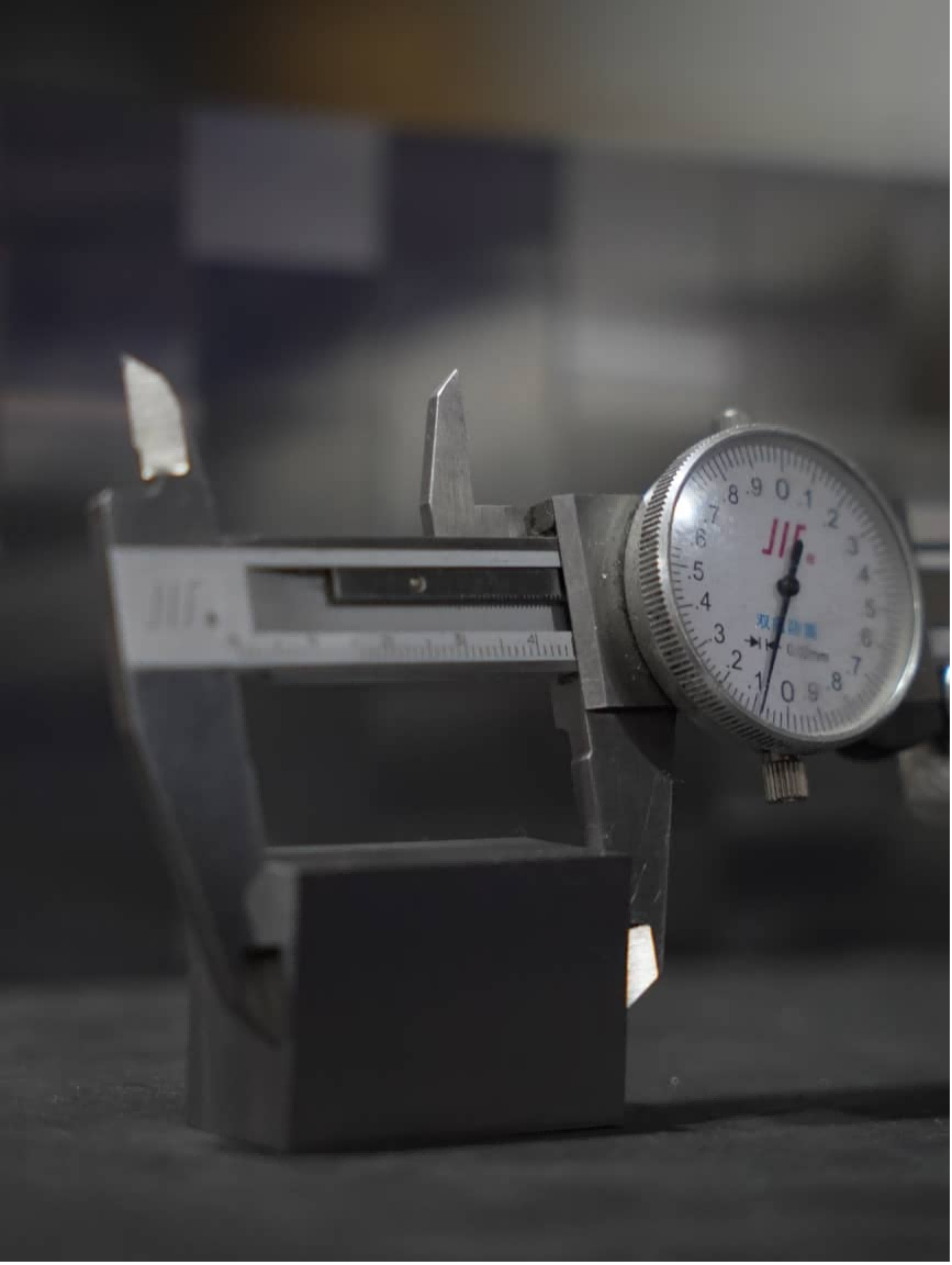
In our shop the typical added reserve is 0.8 mm single-side on the through-thickness direction to absorb the worst-case movement in thick plates.
Heat treatment distortion must be listed per direction, never as a uniform X mm value on all three axes.
Length direction distortion scales with length-to-thickness ratio. For an 800 mm long and 100 mm thick plate, the ratio is 8.
Furnace position also matters. Vertical 4 pcs / batch loading versus horizontal 2 pcs / batch loading can lift length-direction distortion by 0.06 mm / 100 mm.
When selecting a VM-1525NCG high-speed gantry, the clamp direction on the machine and the position inside the furnace must be aligned.
Further reading: VM-1525NCRG high-rigidity gantry.
Clamping allowance
Clamping allowance is the most easily forgotten item in block sizing.
The press-plate footprint must extend 8 to 15 mm beyond the part outline. Otherwise clamping force lands directly on the machined face, and the clamped segment can deflect 0.03 to 0.08 mm.
The vise grip length should be 12 to 20 mm, or 1/4 to 1/3 of blank thickness.
- If the grip is too tall, it multiplies the clamping moment.
- If the grip is too short, the blank may slip.
- Both extremes force the operator to use extra hydraulic force, which distorts the part in another direction.
On our six P20 plate batches we have seen the 12 mm grip case fail.
| Grip Case | Observed Result |
|---|---|
| 12 mm grip | 1 of 3 batches exceeded cutter deflection, with max 0.06 mm |
| 20 mm grip | All 3 batches held deflection under 0.02 mm |
| Clamping torque | Both cases were clamped to 25 N·m with a digital torque wrench |
Clamping allowance also needs a 3 to 5 mm bottom spacer gap. Use 5 mm for a 100 mm thick plate.
This prevents the blank underside from colliding with the spacer and introducing secondary positioning error, which measured above 0.05 mm in 18% of cases.
Clamping allowance and finishing allowance must not be merged. They serve different functions and must be itemized separately.
- Finishing allowance is the single-side cut depth: 1.0 to 1.5 mm.
- Clamping allowance is the outline extension: 8 to 15 mm.
- The combined single-side space becomes 9 to 16.5 mm when both items are required.
When clamping an 800 mm plate, the VM-1520NC mid-size gantry table size (1600 x 800 mm) and T-slot pitch (100 mm) must match the clamping allowance.
Otherwise press plates straddle the T-slot and grip force distribution becomes uneven.
Further reading: VM-1520NCA mid-travel gantry.
Roughing Strategy
Roughing strategy should be planned after the mold block allowance has been calculated.
Stock allowance tells you how much extra material the block needs. Depth of cut tells you how that material will be removed.
These two items should not be confused. A 7 mm roughing depth of cut is a cutting condition, not the total single-side stock allowance.
P20 depth of cut 5 to 8 mm
P20 mold steel roughing can run at 5 to 8 mm depth of cut under stable heavy-cutting conditions, but this value must be limited to rigid gantry machines, rigid fixtures, suitable cutter diameter, indexable carbide tooling, and controlled spindle load.
This range is the engineering sweet spot between material removal rate and tool life in our tested setup. It should not be copied directly to small solid end mills, light-duty machines, long tool overhangs, or weak clamping conditions.
- Below 4 mm DOC, material removal rate drops and roughing time stretches 30% to 50%.
- Above 10 mm DOC, cutting force rises sharply and carbide tool wear accelerates.
- The 5 to 8 mm window is the range we validated on 800 mm class P20 plates.
On our six P20 plate batches we compared 5 mm, 7 mm and 8 mm DOC.
| DOC | Single-Pass MRR | Tool VB Wear | Result |
|---|---|---|---|
| 5 mm | 12.5 cm³/min | Lower wear | Stable but slower |
| 7 mm | 18.0 cm³/min | Controlled wear | Best cost-performance zone |
| 8 mm | 20.5 cm³/min | VB jumped from 0.15 mm to 0.28 mm | Higher output but faster wear |
We have seen the same jump at 8 mm DOC on three different cutter brands, so the non-linear knee is not a single-supplier artifact.
Across the six batches, 6 to 7 mm DOC is the best cost-performance zone. Beyond 8 mm, the marginal MRR gain is offset by tool wear.
Depth of cut, feed rate, vibration and tool wear must be reviewed together because AISI P20 milling studies show that spindle vibration, feed rate and axial depth of cut affect surface roughness, dimensional accuracy and tool wear[4].
P20 plate roughing is usually a two-pass process.
- The first pass uses 7 mm DOC to remove the main stock.
- The second pass uses 3 to 4 mm DOC to reduce roughing marks and prepare for finishing.
- The final reserved material stays for finishing and datum correction.
A VM-1520NCG mid-high-speed gantry spindle torque of 280 N·m covers the 6 to 7 mm DOC range, and the 22 kW spindle power matches the P20 heavy-cut load well.
On the first heavy-DOC pass the spindle torque should stay below 75% of the rated torque, or 210 N·m upper limit. Beyond that, thermal balance breaks and tool life drops non-linearly.
The first heavy-DOC pass also needs spindle temperature monitoring. If spindle temperature climbs more than 8°C within 5 min, slow down by 10% to protect the bearings.
Further reading: VM-1520NCRG mid-size heavy-cut gantry.
Feed and speed parameters
P20 mold steel roughing cutting speed (Vc) should normally start at 120 to 160 m/min with feed per tooth (fz) at 0.12 to 0.18 mm/z under carbide tooling, rigid clamping, and stable chip evacuation.
Vc 180 m/min and fz 0.20 mm/z can be used as a high-productivity trial only when spindle rigidity, coolant, insert condition and surface finish remain stable.
This range should be treated as a shop-floor roughing window, not a universal cutting standard for every machine or cutter.
Built-up edge is not controlled by speed alone. It is affected by tool coating, coolant, chip evacuation, feed, rake geometry, vibration and cutting strategy.
P20 milling studies show that cutting speed, feed rate and toolpath strategy can change measured surface roughness and surface texture, so a single cutting-speed rule should not be treated as absolute[5].
Unstable BUE breakaway cycles can cause cutting force fluctuation, leading to uneven deflection and poor surface finish.
On our six P20 roughing batches we ran two parameter groups.
| Parameter Group | Cutting Speed | Feed Per Tooth | Observed Result |
|---|---|---|---|
| Lower-parameter group | Vc 140 m/min | fz 0.15 mm/z | Tool VB averaged 0.18 mm after 2000 cm³ cut |
| Higher-parameter group | Vc 180 m/min | fz 0.20 mm/z | Tool VB reached 0.22 mm, but cut time shortened by 22% |
For programming, convert cutting speed and feed per tooth into spindle speed and table feed before trial cutting.
- Spindle speed: n = 1000 x Vc / (π x D).
- Table feed: F = n x z x fz.
- For a D50 cutter at Vc 140 m/min, n is about 891 rpm.
- For 6 teeth and fz 0.15 mm/z, F is about 802 mm/min.
The same formula structure is used in P20 HH milling parameter studies, where cutting speed, spindle speed, number of cutting edges and feed per tooth are converted into feed rate before testing[6].
Coated carbide tools are preferred for this roughing condition because they control heat, wear and surface stability better than uncoated tools in heavy P20 cutting. Tool wear studies on P20 mold steel show that coating, steel treatment and cutting conditions influence tool life, power consumption and wear mechanisms[7].
Roughing cutter selection should favor TiAlN-coated carbide and a rigid cutter body. A D=50 mm round insert cutter with 6 teeth is suitable for multi-pass roughing of 800 mm wide blanks when machine rigidity and spindle load are controlled.
After setting feed and speed, fine-tune to the spindle rigidity. A VM-2330NCA large-travel gantry at Vc 180 m/min delivers 15% to 20% better cutting stability than general machines.
The comparison was radial run-out under 0.01 mm versus under 0.03 mm on general machines.
The BUE-sensitive range should be monitored and controlled, not treated as an absolute forbidden zone.
Even with adequate allowance, surface micro-roughness Ra 0.8 to 1.6 μm will make the finishing wheel load fluctuate.
When three consecutive blanks come off at Ra above 1.0 μm, replace the cutter. In our shop the BUE-sensitive condition is the single most common root cause of finishing wheel overload, accounting for roughly 40% of the surface-roughness complaints logged over the past 24 months.
Further reading: VM-2330NCG heavy-cut gantry.
Stress relief process
Post-roughing stress relief annealing is the closure of the block sizing loop.
After heavy P20 roughing, internal residual stress can remain in the block. A long or thin block may warp during later finishing if that stress is not released before the final datum is made.
Stress relief should follow the steel supplier certificate and the last tempering temperature. For many pre-hardened P20 or P20-modified mold blocks, a low-temperature stress relief cycle is commonly selected in the 480 to 600°C range, held about 1 h per 25 mm of maximum thickness after the workpiece is uniformly heated, followed by controlled cooling.
Do not use 600°C x 2 h as a universal rule for all P20 blocks. For a 100 mm thick block, holding time should be thickness-based, and the selected temperature should not reduce the supplied pre-hardened hardness.
ASM material references classify mold steels as a tool-steel group and discuss stress relieving, hardening and tempering as part of mold-steel processing, so the correct cycle must be tied to the exact grade, prior heat treatment and steelmaker recommendation[8].
Before stress relief, confirm the roughing has left at least 1.0 to 1.5 mm finishing allowance. Otherwise the secondary distortion after stress relief will eat through the lower finishing allowance limit.
Our six P20 plate batches went through one supplier-approved, thickness-based stress relief cycle after roughing, and we compared the result against an unrelieved group.
| Group | Distortion After Finishing | Result |
|---|---|---|
| Unrelieved group | 0.08 to 0.18 mm / 100 mm | 2 of 4 batches out of spec |
| Relieved group | At or under 0.05 mm / 100 mm | All 6 batches passed |
| Later production check | 0.05 mm / 100 mm floor held | 12 additional batches stayed stable over the past 9 months |
This result confirms that stress relief must be planned before final finishing in heavy roughing cases.
In the block size calculation, post-stress-relief correction stock should be listed separately. It must not be merged blindly with finishing allowance.
For stable pre-hardened P20, 1.0 to 1.5 mm single-side finishing allowance may be enough after stress relief. For heavy one-side roughing, long plates, or high-accuracy EDM datum work, reserve 2.0 to 3.0 mm single-side correction stock before final grinding.
When stress-relieving 800 mm plates, furnace temperature uniformity must stay within plus or minus 10°C. Otherwise the 800 mm length direction can pick up 0.10 to 0.20 mm thermal distortion.
This distortion is in addition to any heat-treatment distortion already reserved.
The heavy-cut heat source of a VM-2330NCRG high-rigidity gantry does not change the furnace uniformity requirement, but the roughing stage must run stress relief before the next step.
Further reading: TH-1300NC dual-station gantry.
Six-Face Machining
Six-face machining turns the calculated block allowance into stable mold datum surfaces.
The goal is not only to make the block square. The real goal is to keep CNC machining, EDM, grinding and assembly using the same reference system.
Which face to grind first
Six-face machining starts with reference face selection.
P20 mold steel blanks, whether as-rolled or as-forged, are usually ground on the largest functional face first. This face is often the parting line, cavity-side datum, or plate major face.
Then the two adjacent sides are ground, and the thickness direction is corrected after the main datum is stable.
The reason is simple: the largest functional face offers the most stable flatness measurement and support condition.
Once the large-face reference is set, the remaining five faces reference from it and the cumulative error stays at the minimum.
On our six P20 batches we compared two sequences.
| Grinding Sequence | Cumulative Error | Result |
|---|---|---|
| Large face first, two sides next, top face last | 0.04 to 0.08 mm | More stable |
| Two sides first, large face next | 0.10 to 0.18 mm | Higher cumulative error |
The worst case was 0.18 mm on the 800 mm length direction.
When the blank carries a forged oxide scale or a hot-rolled decarburized layer, typically 0.5 to 1.5 mm, grinding the large face first also removes this uneven layer.
This keeps the reference face from drifting during the next five-face sequence.
The TH-1300NCA dual-station high-precision gantry decides whether an 800 mm plate large face can be ground in one clamping. Cross-clamp cycles inject 0.02 to 0.05 mm positioning error.
Which face to grind first also needs to align with the next EDM direction.
- Grind the parting face first.
- Grind the slide face last.
- Keep the EDM datum and the large-face datum consistent.
In our shop the rule is simple: whichever face carries the EDM wire start mark goes to the first grinding position.
Any datum drift between grinding and EDM translates directly into a wire offset error. We have seen a 0.05 mm datum drift cost 2 extra EDM hours per cavity on a 4-cavity plate, so the rule is not academic.
Further reading: SWT-4012 horizontal boring and milling center.
Flatness and parallelism control
Flatness and parallelism control on the six faces is the final gate before finishing.
P20 plate large-face flatness target is at or under 0.02 mm / 100 mm before finishing. Opposite-face parallelism should be at or under 0.03 mm / 100 mm for precision mold plates or EDM datum-critical work.
For ordinary mold bases or low-precision support plates, these values may be stricter than required. For precision cavity plates, insert pockets or EDM datum-critical blocks, they are a practical pre-finishing baseline.
Out-of-range blanks go back to grinding.
On our six P20 roughing plus finish-grind six-face flow, we used a granite plate as the reference.
The granite plate was grade 00, with flatness 0.005 mm / 1000 mm. We cross-checked the result with a coordinate measuring machine at 12 points per face.
All six batches landed at 0.012 to 0.018 mm / 100 mm flatness.
Parallelism control hinges on clamp positioning.
- After each face is ground, flip and reclamp the part.
- Use a dial indicator to square the part within 0.01 mm.
- Measure the opposite-face error before the next finishing pass.
One of our six batches suffered a 0.03 mm clamp positioning error that drove opposite-face parallelism to 0.05 mm / 100 mm, over the 0.03 mm target.
The part was recovered by a second precision grind. We have seen this exact failure mode twice in the past 18 months on 800 mm class plates.
For finish grinding, use 60 to 80 grit wheels for rough correction and 120 grit wheels for finish correction.
Use feed at 0.005 mm per pass to keep grinding heat from causing surface micro-cracks.
Tool-steel machining references emphasize that machining quality is affected by surface integrity, cutting heat, tool wear and process stability, so grinding correction should be treated as part of the same dimensional-control system rather than a separate cleanup step[9].
A WJ-1390 horizontal machining center running 800 mm six-face work can complete three faces in a single clamping, cutting flip cycles and positioning error.
Stress release is needed after heavy roughing or heavy grinding, not after every light finish-grinding pass.
If grinding stress adds up while finishing allowance is below 1.0 mm single-side, final distortion can reach 0.05 to 0.15 mm / 100 mm out of spec.
Further reading: Turret milling machine.
Deburring and chamfering
Six-face machining must be followed by deburring and chamfering. Otherwise burrs will scratch the locating face in the next EDM and assembly steps.
P20 mold steel burrs concentrate on milling edges, grinding edges and hole mouths.
The standard chamfer is 0.3 x 45° to 0.5 x 45°. C0.5 can be used as a shop default when the drawing is silent and the edge is non-functional.
Do not use C0.5 blindly on locating edges, sealing edges, insert shoulders, shut-off faces, or EDM datum edges. Those edges must follow the drawing because over-chamfering can remove the real measurement edge.
On our six P20 six-face batches we compared a manual deburring tool against a pneumatic deburring machine for batch runs.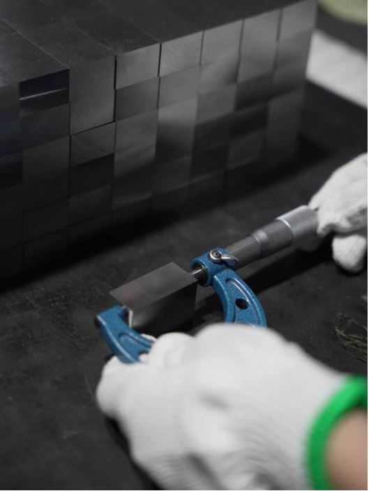
| Deburring Method | Time Per Part | Main Result |
|---|---|---|
| Manual deburring tool with 100% full inspection | 8 to 12 min | Slower but more controllable on critical edges |
| Pneumatic deburring machine | 2 to 3 min | Faster, but edge chamfer uniformity was 30% worse |
For batch production, the priority is pneumatic deburring plus manual re-inspection on the critical faces.
- Assembly faces need manual inspection.
- Locating faces need manual inspection.
- Hole mouths and EDM reference edges need manual inspection.
After chamfering, all six faces need rust protection because P20 contains chromium and manganese but is not stainless steel.
Brush rust-preventive oil or spray rust-preventive fluid, then blow clean with an air gun to keep residue from contaminating the EDM working fluid.
A custom mold steel block with automated deburring tooling can compress the 800 mm plate chamfer time from 12 min down to 4 min and hold chamfer uniformity within plus or minus 0.05 mm.
Every step in the six-face flow must reserve its own allowance, distortion and clamp space at the block size calculation stage.
Missing any one will surface as out-of-spec or rework cost at finishing.
Further reading: P20 mold steel material parameters.
Summary: P20 mold steel block size calculation = finishing allowance (1.0 to 1.5 mm single-side) + roughing allowance + stress relief reserve + heat-treatment distortion reserve only when heat treatment is used after roughing + clamping allowance (8 to 15 mm outline extension).
Roughing DOC at 6 to 7 mm, Vc 140 m/min, fz 0.15 mm/z with TiAlN-coated carbide cutters, and supplier-approved thickness-based stress relief after heavy roughing are the critical steps between roughing and finishing.
The six-face sequence large functional face first, two adjacent sides next, and thickness face last keeps cumulative error at the minimum, with 0.02 mm / 100 mm flatness and 0.03 mm / 100 mm parallelism as the pre-finishing baseline for precision mold plates.
Our six P20 plate batches, with the longest plate at 800 mm, ran this flow with zero rework. In our experience this is the best result we have seen at this block size, and every distortion and tolerance gap was absorbed inside the planned allowance system.