

Guide pin holes, ejector pin holes, and cooling holes may look similar on a mold drawing, but they do different jobs.
A guide hole keeps the mold plates aligned. An ejector pin hole guides a pin that moves every molding cycle. A cooling hole carries water, oil, or another fluid through the mold. Each hole therefore needs a different machining and inspection method.
In this article, “guide hole” means the mounting bore for a guide pin or guide bushing. It does not mean the finished sliding bore inside a purchased guide bushing. The mounting bore holds the component in the plate; the bushing bore guides the moving pin.
The dimensions and examples below explain how to plan the work. They are not universal mold specifications. The approved drawing, component data, tool data, customer requirements, and the shop’s approved process must always take priority.
What Each Hole Must Do
| Hole type | Main job | Main failure risk |
|---|---|---|
| Guide pin or guide bushing mounting hole | Keep the mold plates aligned | Binding, plate mismatch, or fast guide wear |
| Ejector pin hole | Guide a moving ejector pin | Sticking, bending, breakage, wear, or flash |
| Cooling hole | Carry coolant through the mold | Low flow, leakage, or a weak steel wall |
A hole can have the correct diameter and still fail. The center may be in the wrong place, the hole may lean to one side, or its axis may curve through the plate.
- Diameter is the size of the hole.
- Position is the location of the hole center.
- Perpendicularity shows whether the hole is square to the reference surface.
- Straightness shows whether the axis stays straight through the depth.
- Roundness shows whether one section of the hole is circular.
- Cylindricity describes the shape of the complete bore.
- Coaxiality means that holes in different plates follow the same centerline.
ISO 1101 provides the basic rules for geometrical tolerances such as form, direction, and location.[1] ISO 5458 adds rules for hole patterns and related groups of features.[2]
Read the Drawing
Review the complete mold assembly before machining one plate. A hole that looks safe on one drawing view may hit an insert, screw, ejector pin, sensor, hot-runner part, or another cooling line at a different depth.
Check these items before cutting:
- Finished diameter and tolerance
- Hole position and datum
- Hole depth and full-diameter depth
- Through-hole or blind-hole condition
- Plate thickness
- Perpendicularity and surface-finish requirements
- Counterbore, shoulder, thread, plug, and seal details
- Plate material and hardness
- Actual component dimensions
- Nearby pockets, screws, dowels, inserts, and channels
- Required inspection, flow test, and leak test
Create a hole schedule that lists the plate name, coordinates, diameter, depth, function, tool sequence, finishing method, and inspection method. Also record the drawing revision. This prevents a clearance hole from being treated as a guide hole and prevents drill-tip depth from being confused with full-diameter depth.
The material condition changes the machining plan:
- Annealed steel is usually easier to drill and ream, but later heat treatment may move the hole.
- Pre-hardened steel can often be machined to final size without another hardening cycle, but tool wear and cutting load are higher.
- Fully hardened inserts may need carbide drilling, EDM, internal grinding, or jig grinding.
- Stainless mold steel can work-harden if the tool rubs instead of cutting.
For related material information, see P20 pre-hardened mold steel, 45 steel for mold bases and support parts, and the mold steel supply and machining page.
Do not choose a fit from nominal size alone. ISO 286-1 separates nominal size from tolerance limits and the final fit between mating parts.[3]
When plates are ordered partly machined, the drawing must state which holes, pockets, threads, and datum faces are included in the mold semi-finished machining scope and which features will be finished by the mold shop.
Set the Datums
A datum is the reference used to locate and inspect a hole. Critical holes should normally be related to finished plate edges, dowel holes, locating holes, the mold centerline, or approved cavity datums.
Do not locate guide or ejector holes from saw-cut stock, flame-cut edges, rough pockets, or surfaces that will later be ground.
Before machining:
- Clean the fixture and the underside of the plate.
- Make sure the plate sits fully on its supports.
- Probe or indicate the approved datum.
- Check the actual plate thickness.
- Verify the work offset and tool length.
- Check toolholder and tool runout.
- Make sure clamps do not block the toolpath.
- Check the setup again after tightening the clamps.
A small chip under one corner can tilt the plate. The hole may start at the correct coordinate but move sideways as it becomes deeper.
Related plates can be machined in three main ways:
- Separate machining: Each plate is set from the same datum. This is fast, but setup errors from different plates can add together.
- Stack machining: Several plates are clamped together and drilled in one setup. This can improve alignment, but chips, burrs, and clamp pressure between the plates must be controlled.
- Assembly finishing: Plates are rough-machined separately, assembled from finished datums, and then final-machined together. This gives strong alignment control but costs more time.
Reducing repeated setups can improve hole position. See this example of reducing re-clamping in mold base machining. Large or multi-face work may also use a horizontal machining center or a gantry machining center.
Plan the Machining Order
Heavy pocket milling can release stress inside the plate. A plate may look flat while clamped and move after it is released.
A safer order is:
- Rough-machine large pockets.
- Rough-drill major holes.
- Leave material for final finishing.
- Release the clamps and measure the plate.
- Stress-relieve the plate when the material and process require it.
- Finish the datum surfaces.
- Set the plate again from the final datums.
- Finish the critical holes.
- Measure the plate again after unclamping.
If a corner rises only after the clamps are released, the fixture was holding a distorted plate flat. Changing the CNC coordinates will not solve that problem.
Do not finish guide bores and then remove a large pocket next to them. The later cut may move the finished bore. For raw block preparation, see the CNC duplex milling machine and this mold base machining workflow.
Prepare the Entry
A long drill needs a flat and stable entry. If the surface is rough, curved, or angled, first make a flat area with a spot face or milling cutter.
A spotting tool helps a short drill start in the correct place, but it does not guide a long drill through a thick plate. Deep-hole tools may need a pilot hole or guide bushing.
The pilot must be straight, clean, round, and aligned with the required axis. Its diameter, depth, and entry shape must follow the instructions for the exact drill.
Do not run a long unsupported drill at full speed before it enters the pilot.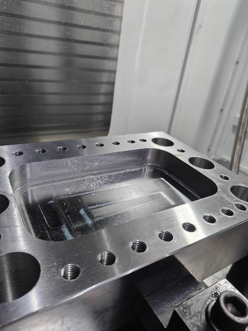
Machine Guide Holes
Guide pin and guide bushing holes control mold alignment. The important features are the bore position, bore size, hole axis, shoulder depth, mounting fit, and alignment with the matching component.
A vertical machining center can combine drilling, boring, counterboring, and tapping in one setup. See the dual-tool-magazine vertical machining center for one equipment example.
Measure the Component
Confirm the exact part number before final boring. A guide component may have a press-fit diameter, sliding diameter, shoulder, flange, relief, chamfer, lubrication groove, or retaining feature.
Machine the plate for the mounting diameter, not the internal sliding diameter.
Check the component’s minimum and maximum outside diameter, shoulder size, wall thickness, recommended mounting fit, and inspection requirements after pressing. Two suppliers can sell the same nominal size with different tolerances.
Drill, Bore, and Ream
Do not drill a precision guide bore directly to final size. A drilled hole may be off-center, tapered, rough, oval, or curved.
Drilling, boring, and reaming do different work:
- Drilling removes most of the material.
- Boring enlarges an existing hole with a single cutting point and can correct a small position error.
- Reaming removes a small amount of material to improve size and finish, but it normally follows the existing hole.
Harvard’s machine-shop terminology also separates drilling, boring, and reaming as different hole-making operations.[4]
A practical sequence is:
- Spot the hole.
- Drill undersize.
- Check the rough position if the risk is high.
- Bore close to final size when position matters.
- Ream to final size when the pre-hole is already straight and correctly located.
- Hone or grind if roundness, straightness, or finish is tighter than reaming can hold.
A shallow boring cut cannot correct a deep hole that curves through the full plate. The complete guide length must be checked.
Use the tool supplier’s cutting data. Spindle speed and feed can be calculated as:
n = 1000Vc / (πD)
Vf = n × fn
Where:
- n is spindle speed in r/min.
- Vc is cutting speed in m/min.
- D is tool diameter in mm.
- Vf is feed rate in mm/min.
- fn is feed per revolution in mm/rev.
For a calculation example only, assume a carbide-drill supplier gives 60 m/min for a 12 mm drill:
n = (1000 × 60) / (π × 12) ≈ 1,592 r/min
If the stated feed is 0.18 mm/rev:
Vf = 1,592 × 0.18 ≈ 287 mm/min
Do not use these numbers unless they match the actual drill, steel grade, hardness, coolant supply, and hole depth.
Machine the Seat
A guide pin or bushing with a shoulder needs a flat seat that is square to the bore.
Check the seat diameter, depth, flatness, corner radius, and full shoulder contact. Machine the bore and seat in the same setup when possible.
A component may stop on an internal tool radius before reaching the seat. It can then look installed while still sitting at an angle.
Set the Press Fit
Too little interference can allow the component to move. Too much can shrink or distort the internal bushing bore, crack thin surrounding steel, or make the guide pin too tight.
Calculate the full possible fit:
Imin = Dcomponent,min − Dhole,max
Imax = Dcomponent,max − Dhole,min
For example, assume a general press-fit component measures 20.010–20.018 mm and the hole measures 20.000–20.006 mm:
Imin = 20.010 − 20.006 = 0.004 mm
Imax = 20.018 − 20.000 = 0.018 mm
The possible interference is 0.004–0.018 mm. This is only a tolerance example, not a recommended guide-bushing fit. The correct fit depends on the component design, wall thickness, plate material, temperature, and supplier instructions.
Press and Check
Use an arbor press, hydraulic press, or approved fixture. Support the plate close to the hole and apply force along the bore axis.
Before pressing:
- Clean the bore and component.
- Remove burrs.
- Confirm the component direction.
- Measure the hole and component.
- Align the component before applying full force.
Do not hammer a precision guide component into place. Impact can tilt the part, damage its hardened surface, or enlarge the bore entrance.
After pressing, check that the shoulder is fully seated, measure the internal bushing bore, inspect the surrounding steel, and test the guide pin. Do not use uncontrolled abrasive polishing to open a tight bushing.
Fix Guide Problems
Pin is tight at the entrance: Clean the parts, check the lead-in chamfer, remove any raised burr, and measure the pin and bushing entrance.
Pin enters but binds deeper: Check for a bent pin, a curved bore, plate distortion, a tilted bushing, or dirt between plates. One-sided contact marks often show the direction of the error.
When the design allows it, rotate the pin and test again. If the tight direction rotates with the pin, the pin may be bent. If it stays with the mold, the bore or plate alignment is more likely wrong.
Bushing is loose: Check bore size, roundness, cracks, and remaining wall thickness. A repair sleeve must restore the correct centerline as well as the fit. Installing a larger bushing on the same wrong center does not correct the alignment.
Machine Ejector Holes
An ejector pin normally passes through more than one hole size. The head sits in the retainer plate, the shaft passes through clearance holes, and a shorter guide section controls the pin near the molding surface.
Separate the Hole Sections
The drawing should identify:
- Head-pocket diameter and depth
- Clearance-hole diameter
- Guide-land diameter and length
- Relief diameter
- Cavity-side sealing land
Do not make the complete hole a close fit unless the design clearly requires it. A long close-fitting section creates more friction and becomes more sensitive to dirt, heat, and small alignment errors.
Choose the Guide Length
A longer guide land supports the pin better but increases rubbing. A shorter guide land reduces rubbing but allows more sideways movement.
Consider the pin diameter, unsupported length, stroke, part-release force, mold temperature, side load, and plate alignment.
Small, long pins are easier to bend. Risk also rises when the pin pushes on a sloped surface, when the part sticks strongly to the core, or when some pins contact the part before others.
If a pin bends, do not automatically make the guide land longer. The better fix may be a larger pin, a shorter unsupported length, better plate support, a sleeve ejector, or a different ejector position.
Drill and Finish
Choose the drilling direction that gives the flattest entry, shortest tool overhang, easiest chip removal, and lowest risk to the cavity.
Drill-path error often grows with depth, so the exit position is usually less certain than the entry position.
Use the shortest tool that can complete each step:
- Spot with a short tool.
- Drill a stable pilot.
- Change to a longer drill only when needed.
- Enter the pilot at a controlled speed.
- Finish the guide land separately.
Small drills are very sensitive to runout and chip packing. Measure runout near the cutting end, use clean coolant, and stop if burr size, chip color, spindle load, or cutting sound changes.
The guide land may be finished by reaming, fine boring, honing, grinding, EDM, or controlled lapping. For hardened parts, difficult holes, or broken-tool removal, see the precision machining and EDM service.
After EDM, clean the hole and inspect the recast surface. Remaining EDM particles or high spots can scratch the pin.
Fit the Pin End
The ejector end may need to match a flat, curve, draft angle, rib, boss, texture, or local shutoff.
- Install the pin in the final plate stack.
- Move the ejector system to its forward position.
- Mark the extra material.
- Rough-grind the end.
- Reinstall and check the height.
- Finish the contour.
- Test the full stroke.
Mark fitted pins so that each one returns to the same hole. An angled or shaped pin may also need an anti-rotation feature.
Remove the cavity-side burr without rounding the molding edge. Too much rounding can allow plastic flash.
Test the Ejector System
Test each clean pin by itself before installing the complete set. The pin should move through the full guide length without twisting or side pressure.
Then check the assembled system:
- Full forward and return stroke
- Head seating
- Ejector-plate parallelism
- Return-pin action
- Pin height at the cavity
- Contact with inserts or other pins
- One-sided scratch marks
A cold test may not show a heat-related problem. Repeat the movement test at an approved warm condition when the pin sticks only during production.
Fix Ejector Problems
Pin sticks when hot: Check for a bent pin, long guide land, dirt, poor lubrication, head-pocket error, and plate distortion before increasing the clearance.
Thermal growth can be estimated with:
ΔD = α × D × ΔT
For a simple example, a 10 mm steel pin with an assumed expansion coefficient of 11.5 × 10⁻⁶/°C and an 80°C temperature rise grows by about 0.0092 mm.
This does not mean the running clearance drops by 0.0092 mm. The hole also expands. If the pin and plate are similar steel at the same temperature, both grow by nearly the same percentage. Clearance is more likely to shrink when the pin is hotter, the materials differ, or the plate changes shape. NIST notes that steel expansion depends on material and temperature.[5]
Pin breaks near the head: Check whether the head sits flat, the head pocket is centered, the clearance holes line up, and the ejector plate moves parallel. A harder pin will not correct a side load.
Flash forms around the pin: Measure both the pin and the guide land. Check for wear, a rounded cavity edge, pin deflection, high local pressure, or a pin that does not return fully.
A vented ejector is a designed feature. Do not create one by randomly enlarging an ordinary ejector hole.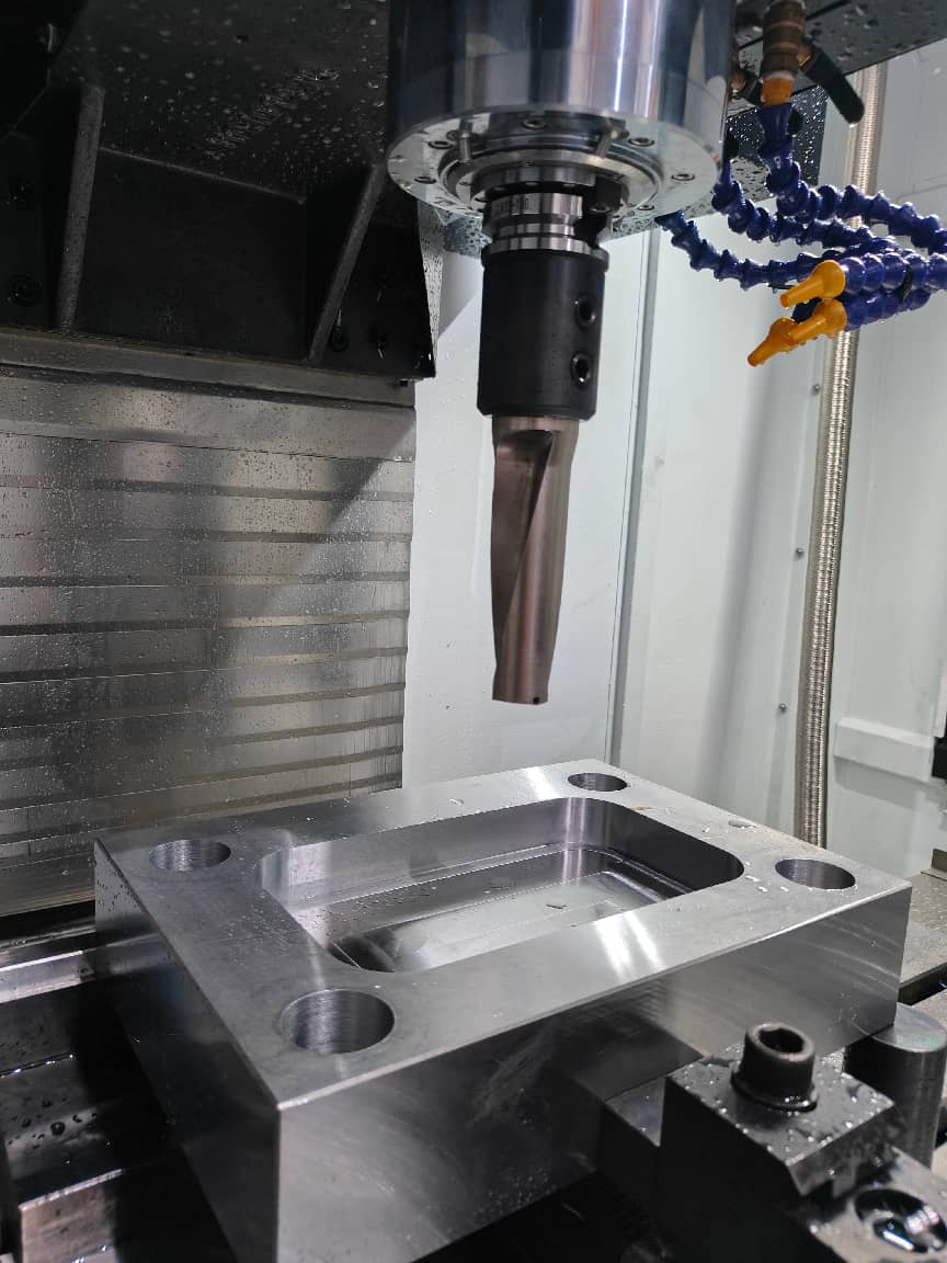
Machine Cooling Holes
A cooling circuit must stay inside a safe steel area, connect fully with its cross holes, carry enough fluid, and remain leak-free.
A circuit can pass a leak test and still have poor flow. Leak testing checks sealing; flow testing checks whether the passage is open enough.
Check the Route
Review the complete route in a three-dimensional model. Check the distance to cavity surfaces, inserts, screws, ejector holes, guide holes, dowels, sensors, hot-runner parts, threads, and other cooling channels.
Do not use the nominal CAD centerline as the only safety check. Allow for entry-position error, drill drift, plate movement, cavity-machining error, and measurement uncertainty.
For final approval, check the worst possible three-dimensional distance from the cavity surface to the outside of the cooling hole. A simple subtraction table can help during planning, but it is not a replacement for the actual CAD and drawing check.
Choose the Diameter and Drill
A larger channel usually gives less flow resistance but removes more steel. A smaller channel fits into tighter areas but is easier to block and may have a larger pressure drop.
Pressure loss depends on the flow speed, channel length, diameter, surface roughness, bends, fittings, and changes in flow area.[6]
Check the full circuit, not only the drilled diameter. A small fitting bore, long plug, narrow cross-hole opening, or misplaced baffle can become the main restriction.
Use:
- Standard drilling for short or moderate holes within the tool’s stated range.
- Long solid-carbide drilling when the machine, tool, pilot, and coolant system support the required depth.
- Gun drilling for deep, straight passages when the correct pilot, guide, coolant, and entry cycle are available.
- EDM drilling for small holes, hardened steel, difficult angles, or repair work.
Deep-hole drilling is a broad group of processes. Gun drilling is one type of deep-hole drilling. Do not use one depth-to-diameter limit for every drill.
Make the Pilot
A gun drill or another guided deep-hole tool needs the correct pilot or guide bushing.
The pilot must match the exact tool for diameter, depth, finish, alignment, and entry shape.
A typical entry is:
- Align the drill with the pilot.
- Rotate at the stated entry speed.
- Feed into the pilot.
- Make sure the cutting section is supported.
- Start coolant as required.
- Increase to the stated cutting speed.
Do not copy pilot dimensions or entry speeds from a different drill series.
Control Coolant and Chips
Coolant must reach the cutting edge and carry chips out of the hole. Check pressure, flow volume, filtration, concentration, temperature, hoses, tool connections, and tank cleanliness.
A pressure reading alone does not prove that enough coolant reaches the cut.
Watch the chips:
- Longer chips may show poor chip breaking.
- Dark chips may show too much heat.
- A sudden drop in chip volume may mean that chips are packing inside the hole.
- Powder-like particles may show a chipped cutting edge.
- Uneven chips may show that one cutting edge is doing more work.
If the chip pattern changes suddenly, stop safely, inspect the drill, check the coolant, and clear the hole.
Peck drilling is not correct for every deep-hole tool. Some conventional drills need pecking. Some gun drills are designed for continuous feed after entering the pilot. Follow the instructions for the exact tool.
Control Depth and Breakthrough
A drill can lose support when it enters a pocket, cross hole, angled surface, or another channel. Reduce feed near breakthrough when the tool procedure requires it.
Measure the real plate thickness. Do not rely only on the nominal drawing value.
For a blind hole, separate these dimensions:
- Drill-tip depth
- Full-diameter depth
- Usable straight-bore depth
- Thread depth
- Bottom clearance
For an ideal pointed drill, the point height is approximately:
h = (D / 2) / tan(θ / 2)
For a 10 mm drill with a 118° point:
h ≈ 3.0 mm
To obtain 30 mm of full-diameter depth from the entry surface, the drill tip would therefore need to reach about 33 mm. Check the real drill geometry before using this value.
Open Cross-Hole Intersections
Two centerlines can intersect in CAD while the real holes create only a small crescent-shaped opening.
Causes include drill drift, entry error, wrong depth, wrong diameter, and plate movement.
A restricted opening can cause low flow, high pressure loss, chip trapping, and scale buildup.
Check the intersection with a borescope, depth probe, measured coordinates, and a liquid-flow test. A regulated low-pressure airflow check may confirm that the holes connect, but it does not prove that the liquid-flow area is large enough.
Remove the internal burr before final cleaning.
Machine Threads and Plugs
Check the tap-drill size, usable thread length, total drill depth, tap lead, chip space, seal location, plug length, and future access.
A blind threaded port needs more total depth than its usable thread length. The drill point, incomplete tap teeth, and chip space all use extra depth.
A plug that is too long can project into the main channel and reduce flow.
Straight threads may seal against an O-ring or machined face. Taper threads normally seal through controlled thread engagement and an approved sealant. Do not use so much sealant that it enters the circuit.
Clean and Flow-Test
Flush every circuit in both directions. Remove steel chips, grinding dust, EDM particles, thread sealant, abrasive residue, rust, and oil sludge.
Open accessible plugs and inspect the cross-hole areas. Use a filter or clean white cloth at the outlet to see when visible dirt has stopped.
Measure flow under controlled conditions and record:
- Circuit number
- Inlet and outlet pressure
- Fluid temperature
- Hose and fitting size
- Flow rate
Do not judge flow only by looking at the outlet stream. Different circuit lengths and bend counts give different normal results.
Record a baseline flow value when the mold is new. It gives the maintenance team a useful comparison when scale or blockage develops later.
Pressure-Test Safely
Use rated plugs, fittings, hoses, gauges, and an approved test procedure.
Hydrostatic testing with a suitable liquid is generally safer than pneumatic testing because compressed gas stores much more releasable energy. Fermilab’s pressure-testing procedure recommends hydrostatic testing whenever possible and requires extra controls for pneumatic testing.[7]
- Confirm the pressure rating of every test component.
- Fill the circuit with the approved liquid.
- Remove trapped air.
- Raise pressure slowly.
- Hold at the specified pressure and time.
- Inspect plugs, threads, seals, inserts, and repaired areas.
- Record pressure, temperature, circuit number, time, and result.
- Release all pressure before touching a plug or hose.
- Drain and dry the circuit.
- Apply the required rust protection.
OSHA requires hazardous stored or remaining energy to be relieved, disconnected, restrained, or otherwise made safe before servicing work begins.[8]
Do not copy a test pressure or hold time from a general article. Use the customer standard, seal and plug ratings, and the shop’s approved procedure.
Check Drill Drift
Drift depends on the drill, pilot, steel, hole depth, machine alignment, coolant, tool wear, and cutting data.
Measure the exit position of a through hole. For blind holes, use suitable methods such as remaining-wall ultrasonic measurement, depth probing, borescope inspection, or a qualified test piece.
Stop drilling if the measured or expected path approaches the minimum allowed wall. A good result on one hole does not guarantee the same result with a worn tool or a different steel plate.
Inspect the Finished Holes
Choose the inspection method from the failure that matters.
Guide Holes
- Measure diameter near the entrance, middle, and bottom.
- Measure in two directions at each depth to find taper or ovality.
- Measure position from the approved datum.
- Check the hole axis and shoulder seat.
- Measure the bushing bore again after pressing.
- Test mold closing under controlled force.
Ejector Holes
- Measure the pin, guide land, relief, and guide length.
- Inspect the cavity-side edge.
- Check the head pocket and plate alignment.
- Test each pin and the complete ejector stroke.
- Repeat at a safe warm condition when heat-related sticking is suspected.
Cooling Holes
- Check entry and exit position.
- Check actual and full-diameter depth.
- Inspect cross-hole openings and internal burrs.
- Check thread depth and plug projection.
- Record flow, leak-test, cleaning, and rust-protection results.
A bore gauge is useful for diameter, taper, and ovality. An air gauge is useful for repeatable close-tolerance diameter checks. A master pin is useful for a quick fit test but does not prove hole position or shape. A borescope shows burrs and intersections but does not provide a full dimensional result.
A coordinate measuring machine can measure the size, shape, and location of features in three dimensions.[9] The probe plan must cover enough of the hole depth to represent the working surface.
The measuring tool must be accurate enough for the tolerance, correctly calibrated, clean, and used at a stable temperature.
Remove a Broken Drill
Do not push a second drill against a broken tool inside an expensive plate.
- Stop the machine.
- Record the tool position and depth.
- Check the nearby cavity, ejector, guide, and cooling features.
- Choose an approved removal method, such as EDM, when suitable.
- Remove EDM residue and damaged material.
- Restore the correct hole center and size.
- Inspect the repaired hole.
- Repeat the required fit, flow, or leak test.
Removing the broken tool is only the first step. The repaired hole must still meet its original function.
Final Check
- The latest drawing revision was used.
- Material and hardness were confirmed.
- Final datums were checked.
- Heavy roughing was completed before final hole finishing.
- Guide-hole measurements and post-press checks were recorded.
- The mold-closing test passed.
- The complete ejector stroke passed.
- Cooling-hole routes and intersections were checked.
- Every cooling circuit was cleaned and flow-tested.
- Leak-test results were recorded.
- Test liquid was removed and rust protection was applied.
- Repairs and approved deviations were documented.
Conclusion
Guide holes, ejector holes, and cooling holes cannot be accepted by diameter alone.
A guide hole must align the plates. An ejector hole must let the pin move through its full stroke. A cooling hole must stay inside safe steel, connect fully, carry enough fluid, and remain leak-free.
The best time to find a shifted guide axis, tight ejector land, drifting cooling hole, or blocked cross-hole opening is before the mold reaches the molding machine.