

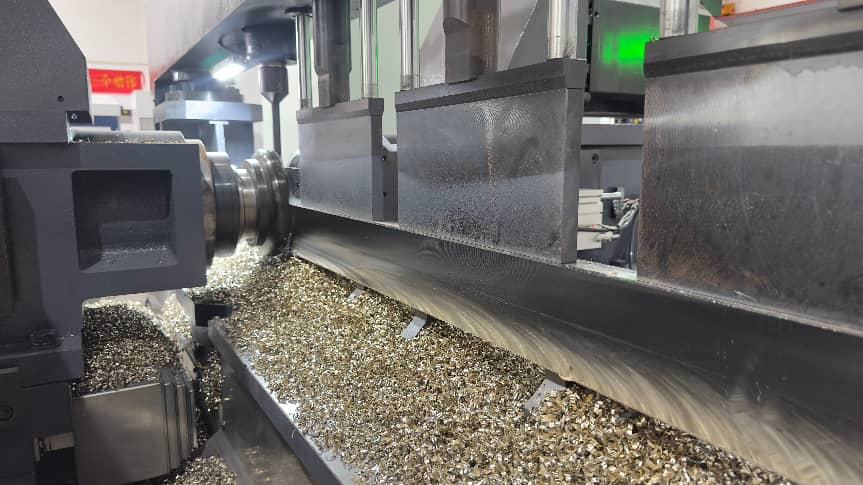
Inspect both milled faces at planned locations, move the stylus across the local cutter marks, and compare each required area with the drawing limit. For process planning, many general mold-base faces fall within Ra 1.6–3.2 µm, while precision mounting or locating faces often target Ra 0.8–1.6 µm. These ranges are practical examples, not universal acceptance limits. Before rework, measure the defect depth and confirm that enough material remains for cleanup, later finishing, and all final dimensions.
| Inspection item | Practical starting point |
|---|---|
| General mold-base face | Ra 1.6–3.2 µm |
| Precision mounting or locating face | Ra 0.8–1.6 µm |
| Small, stable face | At least 5 planned measurement areas |
| Large or critical face | Use a 3 × 3 map with 9 areas |
| Near-limit or unusual result | Take 3 nearby traces |
| Rework decision | Required removal must be below the available stock |
A CNC duplex milling machine machines two opposite faces in one setup. This reduces repeated turning and alignment, but it does not guarantee that both faces will have the same finish. Insert wear, cutter runout, trapped chips, vibration, coolant flow, and uneven support can make one face rougher than the other.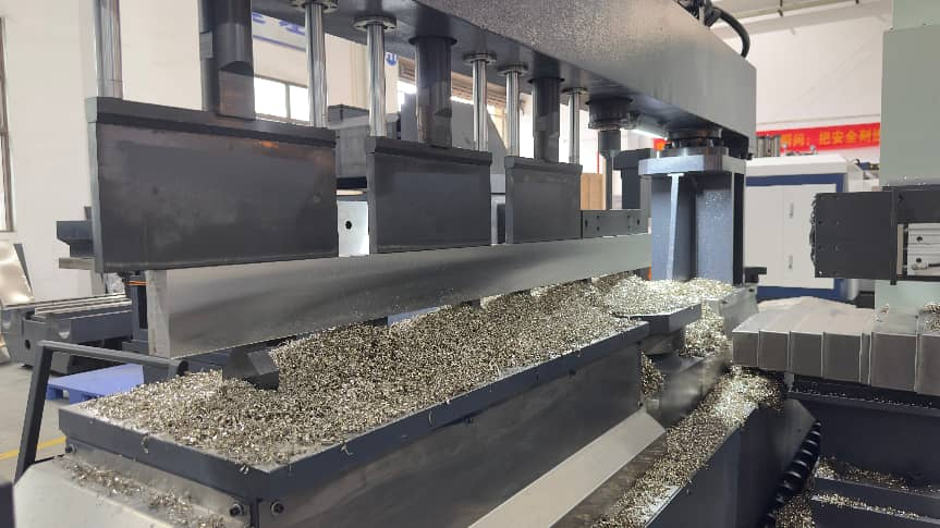
Check the Drawing Before Measuring
The drawing and approved inspection plan decide whether the surface passes. A typical Ra table can help with process planning, but it cannot replace the drawing requirement.
Confirm the following information:
- the required parameter, such as Ra, Rz, Rt, or RSm;
- the maximum or minimum permitted value;
- the exact face or area covered by the requirement;
- the required direction of the machining marks;
- the standard named on the drawing;
- the filter, cutoff, and evaluation length, if specified;
- whether every reading must pass or another approved rule applies;
- separate limits for scratches, pits, chatter, burrs, and edge damage;
- final thickness, flatness, parallelism, and feature-depth limits;
- stock that must remain for grinding, polishing, coating, or later machining.
A drawing may state Ra 3.2 µm maximum, but that does not automatically allow a deep scratch or a visible cutter step. Surface roughness and visible defects are often checked separately.
For current ISO profile measurements:
- ISO 21920-1 covers how profile surface texture is shown on technical drawings;
- ISO 21920-2 defines profile terms and parameters;
- ISO 21920-3 covers the measurement and specification operator.
ISO 4287 and ISO 4288 are older, withdrawn standards. They may still appear on existing drawings. Do not mix their settings with ISO 21920 unless an approved procedure explains the change.
Use Ra Targets That Match the Surface
The required finish depends on how the surface will be used and whether another finishing operation follows.
| Surface use | Practical Ra range | Approximate value in µin | Main inspection point |
|---|---|---|---|
| Rough stock preparation | 3.2–6.3 µm | 125–250 µin | Leave enough stock to remove roughing marks later |
| General mold-base face | 1.6–3.2 µm | 63–125 µin | Check contact, flatness, and visible defects |
| Precision mounting face | 0.8–1.6 µm | 32–63 µin | Check scratches, high points, and contact area |
| Locating face | 0.8–1.6 µm | 32–63 µin | Check flatness, parallelism, and burrs |
| Sliding face | Final target often 0.4–0.8 µm | 16–32 µin | Usually needs grinding or another controlled finish |
| Sealing face | Application-specific | Application-specific | Check lay and continuous scratches across the sealing path |
| Mold cavity surface | Drawing-specific | Drawing-specific | Usually needs grinding, EDM, texturing, or polishing |
The values above are planning ranges. For example, a normal support face may work at Ra 3.2 µm, while a precision locating face on the same block may require Ra 0.8 µm.
One micrometer equals about 39.37 microinches. Common conversions are:
- Ra 0.4 µm ≈ 16 µin;
- Ra 0.8 µm ≈ 32 µin;
- Ra 1.6 µm ≈ 63 µin;
- Ra 3.2 µm ≈ 125 µin;
- Ra 6.3 µm ≈ 250 µin.
A shop description such as “125 finish” normally means about Ra 125 µin, or Ra 3.2 µm. Confirm that the number refers to Ra.
For more background on how roughness affects friction, wear, mold release, and later processing, read Why Surface Finish Is Important in Mold Steel Processing .
Separate the Process Target from the Drawing Limit
A process should normally run below the drawing limit. If production regularly operates at the maximum permitted value, a small change in tool wear or vibration can create rejected parts.
The following is an example of internal control limits for a drawing requirement of Ra 3.2 µm. It is not an industry standard.
| Measured Ra | Example process status | Example action |
|---|---|---|
| Ra ≤ 2.4 µm | Normal | Continue production and normal checks |
| Ra > 2.4 to 2.8 µm | Early warning | Check tool wear and recent measurement trend |
| Ra > 2.8 to 3.2 µm | Close to the drawing limit | Take additional traces and inspect the cutter |
| Ra > 3.2 µm | Over the drawing limit | Handle according to the nonconforming-product procedure |
This type of control plan helps the shop correct a weak process before parts fail. The actual warning values should be based on machine capability, measurement results, and customer requirements.
Do Not Judge the Surface by Ra Alone
Ra is the average size of the small height changes along the measured line. Because it is an average, one deep scratch may have only a small effect on the final value.
- Roughness: small, closely spaced marks produced mainly by cutting.
- Waviness: wider waves caused by vibration, movement, poor support, or distortion.
- Lay: the main direction of the machining marks.
- Defects: scratches, pits, dents, burrs, cracks, chip-drag grooves, and cutter steps.
Two surfaces can both measure Ra 1.6 µm while looking and working differently. One may have regular shallow marks. The other may be smooth in most areas but contain one deep scratch.
- Rz reacts more strongly to larger peaks and valleys than Ra.
- Rt is the total height from the highest peak to the deepest valley over the full evaluation length.
- RSm describes the average spacing of profile elements and can help identify regular cutter marks or wider chatter patterns.
The definition of Rz has not been identical in every historical standard. Record the standard with the result instead of writing only “Rz 8 µm.”
Choose the Right Tester
A portable stylus profilometer is suitable for most routine duplex-milling checks. Before measuring, confirm:
- the instrument is within its calibration period;
- the daily reference check has passed;
- the stylus is clean and undamaged;
- the tip size is suitable for the expected surface marks;
- the correct parameter, filter, cutoff, and evaluation length are selected;
- the tester is fully supported and cannot rock during the trace.
A large stylus tip may not reach the bottom of a narrow groove. This can make a scratch or recessed line appear shallower than it really is.
Skid-type testers are convenient for normal shop-floor Ra checks. Their support follows part of the surface, so some longer waves may not appear clearly in the result.
Skidless testers use an internal reference and record a more complete profile. They are more suitable for measuring chatter, waviness, cutter steps, and local defect depth.
Optical equipment can be useful for narrow scratches, pits, and three-dimensional surface maps. Do not replace a drawing requirement for Ra directly with Sa. Ra is measured along a line, while Sa is calculated over an area.
Verify the Tester Before Use
Use a certified roughness specimen with a value close to the expected workpiece range. For a process near Ra 3.2 µm, a specimen near Ra 3.0 µm provides a more useful check than one near Ra 0.1 µm.
- the certified value;
- the measured value;
- the permitted verification error;
- the instrument and stylus numbers;
- the date and operator.
This check confirms that the tester is working normally. It does not prove that the selected filter, cutoff, measurement direction, or evaluation length is correct.
- clean the reference specimen;
- clean the stylus and skid;
- inspect the stylus for damage;
- confirm the tester settings;
- repeat the check at another approved position;
- stop production inspection if the result still fails.
Clean and Support the Workpiece
Coolant, oil, dust, lint, and loose chips can change the result. A loose chip can also damage the stylus.
Clean the test area with a lint-free cloth, approved solvent, clean air, or a soft nonabrasive brush.
Do not sand, stone, scrape, or polish the area before inspection. These operations change the surface that should be measured.
- straight scratches;
- regular chatter bands;
- cutter overlap lines;
- pits and dents;
- chip-drag grooves;
- raised or recessed insert tracks;
- edge breakout;
- areas with a different shine or texture.
Allow a large or heavily cut workpiece to reach a stable temperature before final thickness and flatness checks. Support thin plates evenly so they do not bend under their own weight or under the tester.
Set the Cutoff Correctly
The cutoff separates short roughness marks from longer surface waves. A cutoff that is too short can remove real machining marks from the result. A cutoff that is too long can include waviness that should be checked separately.
Use the value required by the drawing or approved inspection procedure. Do not change the cutoff after seeing a failed reading.
Under the older ISO 4288 method, turning and milling are treated as periodic profiles. The sampling length is normally selected from RSm rather than directly from Ra.
| RSm range for a periodic profile | Legacy sampling length λc | Legacy evaluation length |
|---|---|---|
| 0.013 < RSm ≤ 0.04 mm | 0.08 mm | 0.40 mm |
| 0.04 < RSm ≤ 0.13 mm | 0.25 mm | 1.25 mm |
| 0.13 < RSm ≤ 0.40 mm | 0.80 mm | 4.00 mm |
| 0.40 < RSm ≤ 1.30 mm | 2.50 mm | 12.50 mm |
| 1.30 < RSm ≤ 4.00 mm | 8.00 mm | 40.00 mm |
This table is a legacy ISO 4288 example. Do not use it as the default setting for an ISO 21920 drawing.
Measure Across the Cutter Marks
Move the stylus across the local milling marks. A trace that follows a groove may remain between two ridges and report a value that is too low.
- For straight marks, measure close to 90 degrees across them.
- For curved face-milling marks, adjust the tester direction at each location.
- For crossed or unclear marks, take traces in two directions and follow the approved decision rule.
Do not let a normal trace cross a hole, edge, engraving, burr, or two clearly different surface areas. Measure a suspected cutter step separately.
Map Both Faces
One center reading cannot represent a large duplex-milled face. Roughness may change at the cutter entry, exit, center, edges, clamp positions, and cutter-overlap areas.
- center;
- entry area;
- exit area;
- upper side;
- lower side.
For a larger or more important face, divide the surface into a 3 × 3 grid and measure nine areas.
| Upper-left | Upper-center | Upper-right |
|---|---|---|
| Middle-left | Center | Middle-right |
| Lower-left | Lower-center | Lower-right |
Add extra measurements at visible defects, cutter overlap lines, locating pads, sealing paths, and other functional areas.
The five-area and nine-area plans are practical shop examples, not universal standard requirements. The final plan should match the surface size, function, process history, and customer requirements.
Use matching positions on Face A and Face B. Accurate opposing faces also provide better reference surfaces for later six-side machining of mold steel blocks .
Compare Face A and Face B
Comparing the same locations on both faces can show whether the problem follows one spindle or cutter head.
| Location | Face A | Face B | Difference |
|---|---|---|---|
| Entry | 1.4 µm | 2.2 µm | 0.8 µm |
| Center | 1.3 µm | 2.3 µm | 1.0 µm |
| Exit | 1.5 µm | 2.6 µm | 1.1 µm |
| Average | 1.40 µm | 2.37 µm | 0.97 µm |
Face B is rougher at every location. The difference is not proof of one specific fault, but it directs the first checks toward the Face B cutter, insert seating, spindle, coolant flow, and chip removal.
There is no universal acceptable difference between Face A and Face B. The key point is whether the difference is repeated over several locations or parts.
Repeat Unusual Readings
Repeat a reading when it is close to the limit, changes sharply from nearby results, or does not match the visible surface. Move the tester slightly sideways instead of tracing exactly the same line again.
| Area | Three nearby readings | Range | Practical interpretation |
|---|---|---|---|
| Area A | 2.4, 2.5, 2.6 µm | 0.2 µm | Readings are close together |
| Area B | 2.1, 3.5, 2.7 µm | 1.4 µm | Check contamination, direction, or a local defect |
| Area C | 3.0, 3.1, 3.2 µm | 0.2 µm | Stable but close to a 3.2 µm limit |
The range in this table is used only to compare the three examples. It is not a universal pass or fail limit.
Do not delete a high result only because the next result is lower. First check whether the stylus crossed dirt, a scratch, an edge, or a different surface pattern.
Do Not Use an Average to Hide a Failed Area
| Location | Ra |
|---|---|
| Entry | 2.4 µm |
| Center | 2.6 µm |
| Exit | 3.6 µm |
| Upper side | 2.5 µm |
| Lower side | 2.7 µm |
| Average | 2.76 µm |
The average is below 3.2 µm, but the exit area is above the limit. If the inspection rule requires each measured area to pass, the surface fails.
An average is useful for monitoring process trends. It should not replace the approved acceptance rule.
Find the Likely Cause
| Surface pattern | Likely cause | What to check |
|---|---|---|
| High Ra over the full face | High feed, worn inserts, rubbing, or an unsuitable cutting edge | Feed per tooth, insert wear, cutting speed, and cutting depth |
| One face is consistently rougher | Problem with one cutter or spindle | Runout, insert height, spindle condition, coolant, and chip flow |
| Regular wide waves | Chatter or machine resonance | Support, clamping, cutter balance, spindle bearings, and speed |
| One straight raised or recessed line | Insert-height error or dirt under an insert | Insert seat, trapped chip, pocket damage, screw, and axial runout |
| Random deep scratches | Chip recutting or chip drag | Chip removal, coolant direction, air flow, and machine cleaning |
| Rough entry or exit area | Poor edge support, impact, or loss of support | Cutter path, edge support, insert condition, and remaining stock |
| Roughness near clamps | Local bending or uneven support | Clamp pressure, support height, plate thickness, and clamp position |
| Pits after milling | Material inclusion, porosity, or particle pullout | Pit depth, nearby areas, steel condition, and material records |
If roughness appears together with squareness or parallelism errors, check the datum setup and clamping method as well as the cutter. See Why Duplex-Milled Steel Blocks Fail Squareness Inspection .
Correct the cause before making another pass. Recutting with the same damaged insert, dirty pocket, or chip problem can make the defect deeper.
Measure the Defect Before Rework
Ra does not show exactly how much material must be removed to clean up a scratch, pit, or recessed cutter track.
- a skidless profilometer in profile or contour mode;
- a contour measuring machine;
- an optical profilometer;
- a depth indicator with a suitable local reference;
- another approved method with enough resolution.
Use the surrounding undamaged surface as the reference. Do not treat the full displayed profile height as the defect depth without removing surface tilt and normal form from the result.
Required removal = Measured defect depth + Minimum cleanup below the defect + Process and measurement reserve
- recessed cutter track: 0.015 mm deep;
- minimum effective cleanup below the track: 0.015 mm;
- process and measurement reserve: 0.010 mm.
Required removal = 0.015 + 0.015 + 0.010 = 0.040 mm
The 0.015 mm cleanup and 0.010 mm reserve are worked-example values, not fixed industry requirements. Each shop should use values supported by its machine, cutter, material, and measurement capability.
Calculate the Available Stock
Use the minimum measured thickness, not the nominal thickness or average thickness.
Available thickness for current rework = Minimum measured thickness − Minimum allowed thickness − Stock reserved for later finishing
| Measurement position | Thickness |
|---|---|
| Corner 1 | 52.22 mm |
| Corner 2 | 52.20 mm |
| Corner 3 | 52.12 mm |
| Corner 4 | 52.18 mm |
The average thickness is 52.18 mm, but the controlling value is the minimum reading of 52.12 mm.
If the minimum allowed thickness is 52.00 mm and 0.05 mm total must remain for later grinding:
Available stock = 52.12 − 52.00 − 0.05 = 0.07 mm
If both faces must be cut equally:
Maximum theoretical removal per face = 0.07 ÷ 2 = 0.035 mm
This is a theoretical maximum. A process reserve may still be required.
- hole and counterbore depths;
- pocket and slot depths;
- datum-to-feature distances;
- case-hardened or treated-layer depth;
- stock required for later grinding or polishing;
- the effect of one-sided cutting on the center plane.
The maximum stock-based removal is the smallest remaining allowance among thickness, feature depth, treated-layer depth, and required later-finishing stock.
Flatness, parallelism, and squareness are not simple stock values. Confirm that the planned setup can still meet them, then measure them again after rework.
For more examples of stock planning, read How Much Stock Should Remain After Duplex Milling .
Compare Required Removal with Available Stock
| Case | Required removal | Available stock | Practical decision |
|---|---|---|---|
| A | 0.040 mm | 0.100 mm | Rework may be possible after checking all other dimensions |
| B | 0.070 mm | 0.070 mm | No margin remains for normal process or measurement variation |
| C | 0.090 mm | 0.060 mm | Required removal is greater than the available stock |
Case A is not an automatic approval. Hole depths, datum positions, treated layers, flatness, and parallelism still need to be checked.
Case B is mathematically equal, but it leaves no reserve. It should not be treated as a safe rework without a specific engineering review.
Case C should not be machined under the proposed plan because the required removal is already greater than the available stock.
Choose the Rework Method
Finish milling is suitable when the roughness problem covers a broad area, enough stock remains, and the corrected machine can still hold thickness, flatness, and parallelism.
- clean insert pockets;
- undamaged and correctly seated inserts;
- acceptable cutter runout;
- stable workpiece support;
- suitable feed, speed, and cutting depth;
- effective coolant and chip removal.
Grinding is normally more suitable when a lower Ra is required, flatness must also be improved, or a small amount of stock must be removed accurately.
After grinding, check thickness, flatness, burn marks, cracks, edge rounding, and any hardness requirement. See What Is Surface Grinding in Mold Steel Processing for an overview of the process.
Polishing is suitable only for shallow, approved correction. Uncontrolled hand polishing can create a low area even when the measured Ra becomes smaller.
Duplex milling can remove the need for grinding on some general steel and mold-base faces, but it cannot replace grinding where very low roughness, tight flatness, or precise final sizing is required. See Can Dual-Side Milling Replace Grinding in Steel Processing?
- the required removal is greater than the available stock;
- a hole, pocket, datum, or center plane would move outside tolerance;
- a hardened or treated layer would become too thin;
- flatness or parallelism cannot be restored reliably;
- the defect crosses a critical sealing or contact area;
- the defect cannot be measured with suitable equipment.
Worked Rework Example
- size: 500 × 400 × 52 mm;
- roughness limit: Ra ≤ 1.6 µm;
- minimum final thickness: 51.90 mm;
- later grinding reserve: 0.02 mm per face, or 0.04 mm total;
- both faces are functional mounting surfaces.
| Location | Face A | Face B |
|---|---|---|
| Entry | 1.3 µm | 1.5 µm |
| Center | 1.2 µm | 1.4 µm |
| Exit | 1.5 µm | 2.3 µm |
| Upper side | 1.4 µm | 1.6 µm |
| Lower side | 1.3 µm | 1.5 µm |
Face A passes at all five areas. Face B fails at the exit.
After cleaning, three nearby Face B exit traces give 2.2, 2.3, and 2.1 µm. The failure is repeatable. A skidless profile shows a recessed cutter track 0.015 mm below the surrounding surface.
Inspection finds a chip under one Face B insert. The insert sat higher than the others and cut a deeper line. The pocket is cleaned, the insert is replaced, and cutter runout is checked before rework.
0.015 mm defect depth + 0.015 mm effective cleanup + 0.010 mm reserve = 0.040 mm
Measured plate thicknesses are 52.08, 52.06, 52.04, and 52.07 mm. The minimum thickness is 52.04 mm.
Gross thickness allowance = 52.04 − 51.90 = 0.14 mm
Stock available for current rework = 0.14 − 0.04 = 0.10 mm
To keep the center plane balanced, engineering approves 0.040 mm removal from each face.
Total current removal = 0.040 × 2 = 0.080 mm
Expected minimum thickness after finish milling = 52.04 − 0.08 = 51.96 mm
Expected minimum thickness after later grinding = 51.96 − 0.04 = 51.92 mm
The predicted final thickness remains 0.02 mm above the 51.90 mm minimum.
| Inspection item | Before rework | After rework | Requirement |
|---|---|---|---|
| Face B exit Ra | 2.3 µm | 1.4 µm | ≤ 1.6 µm |
| Minimum thickness | 52.04 mm | 51.96 mm | Enough stock for later grinding |
| Expected thickness after grinding | Not applicable | 51.92 mm | ≥ 51.90 mm |
| Remaining thickness margin | 0.14 mm before planned removal | 0.02 mm after all planned removal | Greater than 0 mm |
| Original recessed track | 0.015 mm deep | Not detected in the reworked area | No remaining functional defect |
The part is accepted only after roughness, minimum thickness, flatness, parallelism, and affected feature positions all pass.
Record Enough Information
- part number and drawing revision;
- Face A or Face B and the exact measurement area;
- individual readings rather than only an average;
- parameter and acceptance limit;
- standard, filter, cutoff, and evaluation length;
- stylus and tester identification;
- trace direction relative to the cutter marks;
- visible defect and defect-depth results;
- material removed during rework;
- final minimum thickness, flatness, and parallelism.
After rework, measure the full required pattern again. Checking only the original failed point may miss new chatter, entry marks, edge damage, or distortion elsewhere.
Technical References
- ISO 21920-1:2021 — Indication of surface texture
- ISO 21920-2:2021 — Terms, definitions, and surface texture parameters
- ISO 21920-3:2021 — Specification operators
- ISO 4288:1996 — Withdrawn surface-texture assessment standard
- ASME B46.1 — Surface roughness, waviness, and lay
- Mitutoyo Quick Guide to Surface Roughness Measurement
Conclusion
Reliable roughness inspection after duplex milling needs more than one Ra reading. Use at least five planned areas on a small face or a nine-area map on a larger face, measure across the local cutter marks, and compare matching points on Face A and Face B. For planning, general mold-base faces often fall within Ra 1.6–3.2 µm, while precision mounting faces may target Ra 0.8–1.6 µm. Before rework, measure the defect depth, use the minimum actual thickness, subtract later-finishing stock, and leave a process reserve. After cutting, recheck roughness, thickness, flatness, parallelism, and the original defect area.