

Choose a drill tap center for repeat jobs with lots of holes, frequent tool changes, and small cutters. Choose a general-purpose VMC when you need larger fixtures, heavier tools, or tougher roughing. A 30-second saving across 20,000 parts frees about 167 machine hours, but only if slower cutting or extra handling does not give that time back.
Drill Tap Center vs VMC: Start With Your Parts
A drill tap center can mill pockets, faces, and profiles too. Milling by itself does not rule it out.
Here, “VMC” means a general-purpose vertical machining center, typically built around a 40-taper spindle.
| Your production requirement | Machine to evaluate first | Deciding check |
|---|---|---|
| Repeat brackets with numerous drilled and tapped holes | Drill tap center | Complete cycle time, thread quality, and tap life |
| Small pockets and profiles made with small cutters | Drill tap center | Usable spindle speed and actual milling time |
| Tall fixtures or large rotary setups | General-purpose VMC | Tool clearance, travel, and mounted load |
| Extensive roughing with larger cutters | General-purpose VMC | Sustained cutting performance and tool wear |
| Frequently changing part sizes and materials | General-purpose VMC | Coverage of confirmed and repeat jobs |
| Small steel parts with drilling and moderate milling | Either | Trial using the specified material grade and hardness |
Two jobs show the difference clearly:
- Job A: A 150 × 100 × 25 mm bracket with 24 holes, including eight tapped holes, plus two shallow pockets. A drill tap center is worth testing because drilling, tapping, and positioning take up much of the cycle.
- Job B: A 450 × 300 × 180 mm block with deep pockets and a tall fixture. Start with a VMC and see how it handles the complete setup and roughing load.
A long thin part may fit a compact machine quite easily. A shorter part sitting on a tall fixture may not. Overall dimensions can be misleading.
Check the Fixture, Workpiece, and Tool Together
Table size alone does not tell you whether the machine can reach every feature.
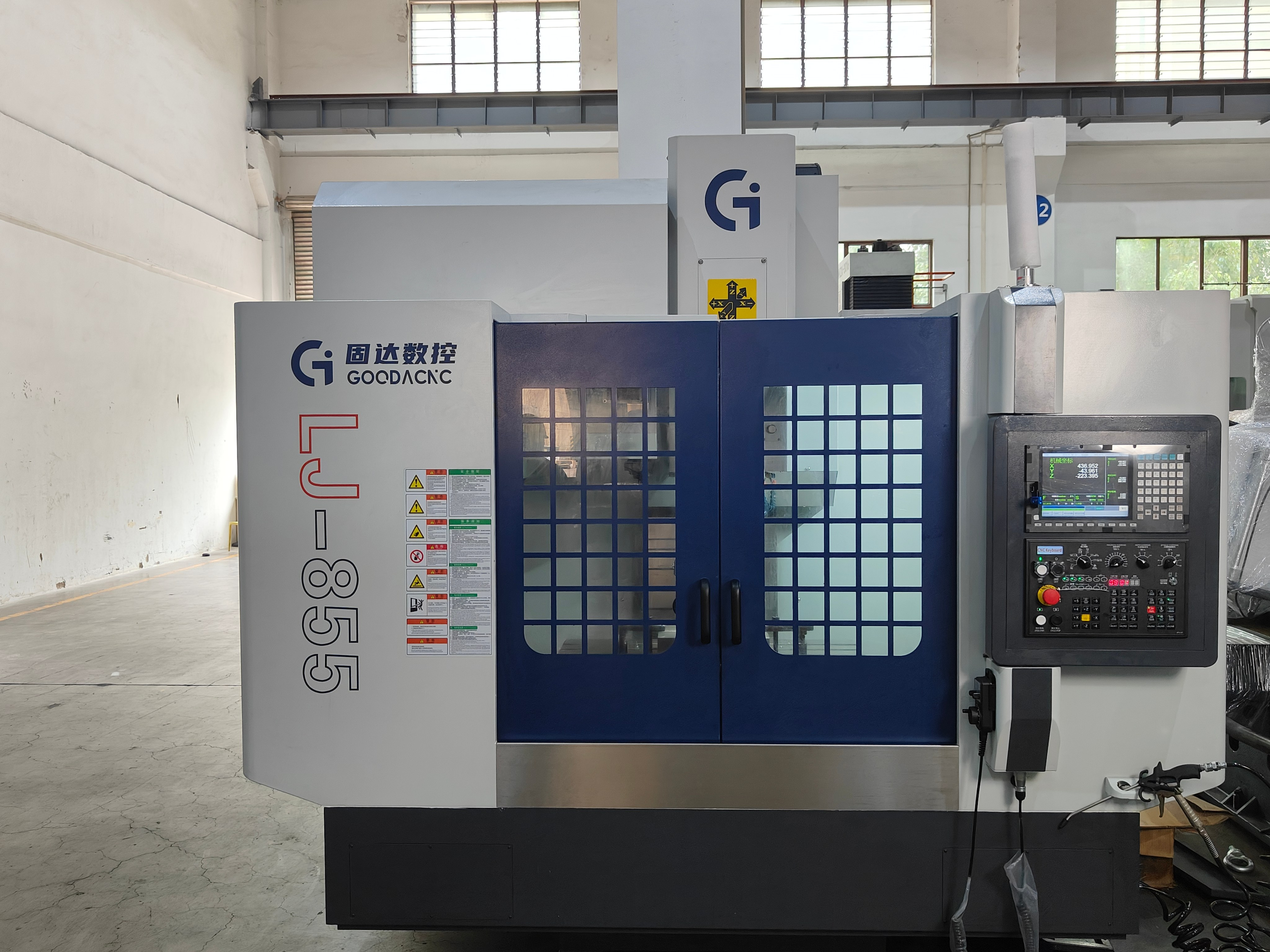
The ASIATOOLS LJ-855 vertical machining center gives a useful example. Its published dimensions let you work through the setup before looking at the final quote.
| Published LJ-855 specification | Value | What to check |
|---|---|---|
| X/Y/Z travel | 800 × 550 × 550 mm | Whether the tool can reach every required feature |
| Worktable size | 1,000 × 550 mm | Fixture footprint, mounting holes, and clamp placement |
| Maximum table load | 500 kg | Total workpiece, fixture, plate, and accessory weight |
| Spindle nose to worktable | 120–670 mm | Clearance with the longest tool and reach with the shortest |
| Tool magazine capacity | 24 tools | Production tools, probe, and replacement tools |
For a quick vertical-clearance check, stack the real dimensions:
| Setup element | Example height |
|---|---|
| Fixture | 120 mm |
| Workpiece above the fixture | 180 mm |
| Tool projection from the spindle nose | 150 mm |
| Approach clearance | 30 mm |
| Total required at approach | 480 mm |
A machine with only 460 mm available at that position will not clear the setup. A machine with 550 mm passes this first check, though tool-change clearance, cutting reach, and clamps still have to fit.
Do the same with weight. A 70 kg workpiece, 45 kg fixture, and 20 kg mounting plate create a 135 kg load.
Check the full setup before choosing a machine.
Send ASIATOOLS your part dimensions, fixture height, mounted weight, and longest tool projection. The machine can then be checked against the real travel and clearance you need.
Discuss My Fixture and Part SizeChoose Spindle Speed From Cutter Diameter
For a cylindrical cutter, the basic calculation is:
Spindle speed, rpm = 1,000 × cutting speed, m/min ÷ (π × cutter diameter, mm).
At an illustrative cutting speed of 200 m/min:
| Cutter diameter | Calculated spindle speed |
|---|---|
| 4 mm | Approximately 15,915 rpm |
| 6 mm | Approximately 10,610 rpm |
| 10 mm | Approximately 6,366 rpm |
| 20 mm | Approximately 3,183 rpm |
The 200 m/min figure is only an input for the calculation. Real cutting speed should come from the tool supplier for the material and operation.
If most of your work uses 4–6 mm tools, higher spindle speed can be useful. If the job is limited by a 20 mm cutter running around 3,200 rpm, torque at that speed matters more.
Ask for the speed–torque curve and separate continuous ratings from short-term peak ratings. A big peak-power number says little about a long roughing cut.
Measure Complete Cycle Time
Count actual tool changes in the program, not holes on the drawing. One drill may cut 30 holes before the machine changes tools once.
For example, 12 tool changes × 1.5 seconds saved = 18 seconds saved per part. Across 20,000 parts, that works out to 100 machine hours before cutting, positioning, or loading differences are added.
Tool-change figures also need comparable test conditions. ISO 10791-9 covers the evaluation of tool-change and pallet-change operating times.[1]
Here is how a small difference can change the full cycle:
| Example cycle element | General-purpose VMC | Drill tap center |
|---|---|---|
| Cutting | 150 seconds | 150 seconds |
| Tool changes and positioning | 70 seconds | 35 seconds |
| Loading and unloading | 40 seconds | 40 seconds |
| Total | 260 seconds | 225 seconds |
The drill tap center saves 35 seconds here, or about 13.5% of the full cycle. But if roughing takes another 45 seconds, its total becomes 270 seconds, which is 10 seconds slower than the VMC.
Include normal probing, chip clearing, and operator handling. Those small pieces of time add up fast in production.
Test Steel Cutting With Your Actual Material
Use the steel grade, hardness, stock size, and machining allowance from the real job. A random block of “steel” in a showroom does not tell you much.
Also separate hole-making from heavy stock removal. A 100 × 60 × 20 mm rectangular pocket contains 120 cm³ of material.
- At an average roughing rate of 30 cm³/min, that volume takes about four minutes to remove.
- At 60 cm³/min, it takes about two minutes.
These are example rates, not claims for either machine. Finishing, corners, and non-cutting motion add more time.
Use the intended holder and tool projection in the trial. NIST research shows that changes in the tool-holder-spindle system, including tool changes and spindle warm-up, can affect milling stability.[2]
If the cutter shifts in the holder, look at end mill pull-out during steel roughing before blaming the machine. Measure tool projection before and after the demanding cut.
For deep drilling, depth-to-diameter ratio matters. An 8 mm hole drilled 160 mm deep is 20D. Pilot strategy, drill design, coolant delivery, and exit deviation all matter when controlling drill wander in deep mold-base holes.
For tapping, test the actual thread size, pitch, depth, and tap type. Track both thread quality and acceptable threads per tap.
Put your hardest cut into the machine trial.
Share the material grade, hardness, deepest hole, largest cutter, and target cycle time. ASIATOOLS can review the spindle, tooling, coolant, and trial conditions around that job.
Discuss My Cutting RequirementsCount Production Tools and Replacement Tools
Count more than just the cutters in the program. Probes, finishing tools, and sister tools all take magazine positions.
| Example requirement | Positions needed |
|---|---|
| Cutting tools | 18 |
| Spindle probe | 1 |
| Sister tools | 4 |
| Total | 23 |
A 21-position magazine cannot hold that setup. A 24-position magazine leaves one nominal spare, assuming oversized tools do not force adjacent pockets to stay empty.
If several jobs stay loaded on one machine, a dual-tool-magazine VMC gives you another option. ASIATOOLS lists a 2 × 32-tool arrangement; whether that extra capacity matters depends on your real tool list.
Tool weight, length, and diameter still matter. A big cutter can block neighboring pockets, and a heavy holder can exceed the changer limit even if the cutter itself looks small.
Verify Accuracy on Finished Parts
A 20.000 ±0.010 mm bore can measure from 19.990 to 20.010 mm. The total tolerance band is 0.020 mm, or 20 micrometres.
Measure the critical features on your own drawing. ISO 10791-7 covers finished-test-piece cutting tests under finishing conditions. It is useful for cutting-accuracy assessment, but it does not prove heavy-roughing productivity.[3]
Check parts after warm-up and again later in the run. Heat from motors, machining, and the room itself can move the machine enough to affect tight dimensions.[4]
Record:
- Critical dimensions and surface finish.
- Cycle time and inspection results for each sampled part.
- Offset adjustments and tool replacements.
- Scrap, rework, and interruptions.
- Measurement equipment and inspection conditions.
A 30-part trial can show drift or obvious inconsistency, but it does not automatically prove long-term process capability. NIST guidance ties capability to a stable process and also discusses sample-size and distribution assumptions.[5]
Measurements close to a tolerance limit need sensible inspection rules too. Instrument resolution is only one part of measurement uncertainty.[6]
Calculate Cost at Your Batch Size
Count the spindle configuration, tooling, fixtures, coolant equipment, chip handling, installation, programming, training, and prove-out.
Cost per good part = total relevant production cost ÷ accepted parts produced.
A faster cycle is not automatically cheaper. More tool wear or more rejected parts can wipe out the time saving.
Suppose the faster machine costs $20,000 more and saves a verified $0.50 per accepted part:
$20,000 ÷ $0.50 = 40,000 accepted parts to recover the premium.
| Annual accepted volume | Simple recovery period |
|---|---|
| 10,000 parts | 4 years |
| 20,000 parts | 2 years |
| 40,000 parts | 1 year |
These are example inputs, not machine prices or guaranteed savings. Financing, tax, and changes in demand are not included.
The saving is easier to justify when it cuts overtime, reduces outsourcing, or opens capacity for confirmed orders.
Setup time matters more in small batches. An extra 30 minutes per setup works out very differently depending on quantity:
| Batch size | Extra setup time per part |
|---|---|
| 20 parts | 90 seconds |
| 200 parts | 9 seconds |
| 2,000 parts | 0.9 seconds |
On a 20-part batch, a machine that saves 20 seconds per cycle still loses overall if setup takes another 30 minutes. Fixture changes, tool loading, datum setting, and first-part inspection all count.
If your work changes constantly in size, tooling, and cutting load, a general-purpose VMC is often the easier starting point.
A drill tap center becomes much easier to justify when repeat volume is high and the cycle saving has already been measured.
Request a quote around the production job.
Provide your drawing, material, batch quantity, tool count, and acceptance requirements. Ask ASIATOOLS to show the proposed machine configuration, required options, and trial scope in the quotation.
Request a Machine Configuration QuoteFinally
Choose the drill tap center when repeat hole-making work gives you a real cycle-time saving; 30 seconds across 20,000 parts is about 167 hours. Choose the VMC when fixture clearance, heavier tooling, or roughing ability decides whether the job can run at all. Compare the finished parts, full cycle, and cost per good part before ordering.