

To keep a deep mold-base hole on line, give the drill a flat entry, use the correct pilot, keep runout and overhang low, and make sure coolant can clear chips all the way out of the hole. Also check where the hole is allowed to finish. An Ø8 mm hole drilled 160 mm deep is already 20D, so a small angular error at the entry can turn into a noticeable position error at the far end.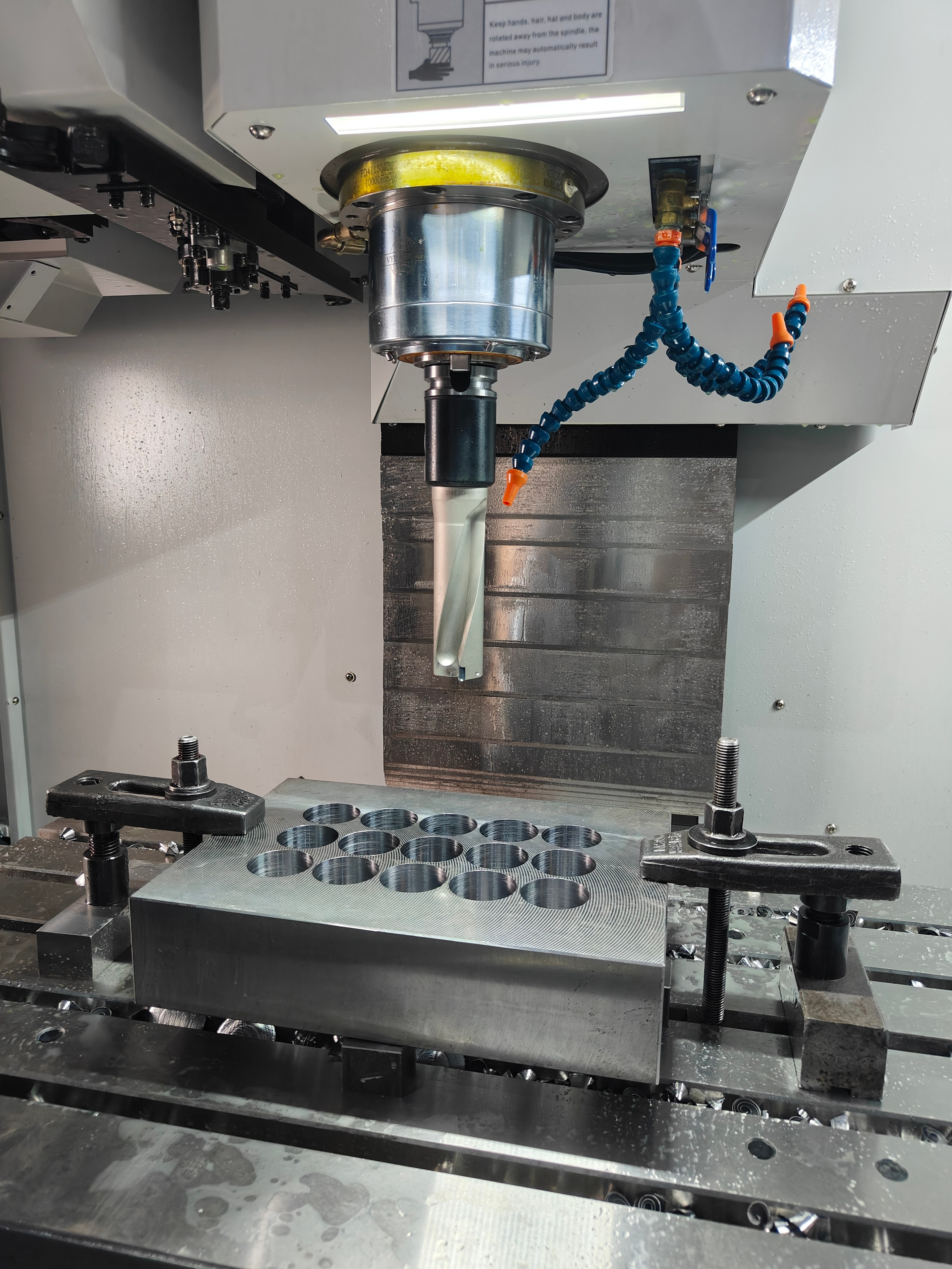
A drill axis that is 0.05° off moves sideways by about 0.09 mm over 100 mm, 0.14 mm over 160 mm, and 0.26 mm over 300 mm. At 0.10°, the error at 300 mm is about 0.52 mm. That may be enough to miss a branch cooling channel or leave too little steel beside a cavity.
Set the Allowed Hole Deviation
Start with the finished hole, not the drill. Check where the hole is allowed to end and how much position error the design can accept. Hole diameter and hole position are separate requirements. A finished bore can measure Ø8.00 mm and still sit several tenths of a millimeter away from its intended centerline. ISO 1101 covers the basic rules for geometric controls including orientation, location and runout.[1]
Check four things on the drawing or CAD model:
- Exit position: How far can the center of a through hole move?
- Cross-hole intersection: How much movement can occur before two channels no longer meet?
- Minimum wall: How much steel must remain beside a cavity, insert, ejector hole, bolt or nearby cooling channel?
- Part value: How much machining has already gone into the plate before this hole is drilled?
If several holes form one controlled pattern, check the datums and position requirements for the whole pattern rather than looking at each diameter on its own. ISO 5458 covers pattern and combined geometric specifications.[2]
Wall thickness deserves a quick worst-case check. Suppose a cooling channel has a nominal 4.0 mm wall to an insert pocket. If the drilled hole moves 0.35 mm toward the insert and the pocket is machined 0.15 mm toward the hole, the remaining wall is:
4.0 − 0.35 − 0.15 = 3.50 mm
With only 2.0 mm of nominal wall, the same combined movement leaves about 1.50 mm. The available steel around the hole can matter more than the hole diameter itself.
For more detail on cooling holes, guide holes and ejector holes, the mold-base hole machining guide covers the main machining differences.
Check the L/D Ratio
Calculate drilling depth divided by drill diameter:
L/D = drilling depth ÷ drill diameter
| Diameter | Depth | L/D | Process to Check |
|---|---|---|---|
| Ø12 mm | 60 mm | 5D | Standard carbide drilling may be practical |
| Ø10 mm | 100 mm | 10D | Through-coolant carbide drill |
| Ø8 mm | 160 mm | 20D | Deep-hole drill with the specified pilot |
| Ø6 mm | 180 mm | 30D | Purpose-built deep-hole drill |
| Ø6 mm | 300 mm | 50D | Compare machining-center drilling with a dedicated deep-hole process |
Use these figures as planning examples rather than changeover rules. A drill sold as 30D, 40D or 50D has the reach for that depth, but the machine, pilot, coolant system and required position tolerance still decide whether the process will work.
Take two Ø8 × 160 mm holes. One passes through thick steel and may allow 0.5 mm of exit movement. The other has to meet an Ø6 mm branch channel near the far end. They are both 20D holes, but the second one leaves much less room for error.
Prepare a Flat Entry
A long drill needs a clean, flat place to start. If it enters on a rough saw-cut face, scale, a step or an angled surface, one side of the cutting edge can touch first and push the tool sideways.
Machine a local flat pad when:
- the plate has a rough saw-cut or flame-cut face;
- scale remains around the drilling point;
- the hole starts close to a step;
- the entry surface is uneven;
- the hole starts on an angled face.
You normally do not need to machine the whole face. For an Ø10 mm drilling system, a flat area around 20–30 mm across can often give the pilot and long drill enough clean contact, as long as the local geometry gives the tools enough clearance.
Use the Correct Pilot
Think of the pilot as a short guide for the long drill. Its job is to establish the starting position and direction before a long, flexible tool enters the plate.
Use the pilot dimensions specified for the exact drill series. Check:
- pilot diameter;
- diameter tolerance;
- pilot depth;
- point geometry;
- required clearance between the pilot and long drill.
For an Ø10 mm drill, a 2D pilot is about 20 mm deep and a 3D pilot is about 30 mm. Those simple figures help explain the notation, but the production setup should follow the pilot depth specified for that drill.
Do not copy a pilot from another drill brand or diameter. An oversized pilot gives the long drill less support. An undersized one can rub the drill body or damage the cutting edges as the tool enters.
Pilot direction matters just as much as pilot diameter. If the pilot axis is 0.10° off and the long drill follows it, the theoretical sideways movement is about 0.35 mm over 200 mm and 0.52 mm over 300 mm.
For a critical hole, check pilot center, diameter, depth and entry condition before loading the long drill.
Do Not Use a Random Spot Drill
Do not automatically add a deep 90° spot before a drill with a 135° or 140° point. The spot geometry and main drill geometry need to work together.
With the wrong spot, the outside of the main cutting edges can touch first. The drill then enters under uneven load instead of being supported evenly.
Many deep-hole systems use a matched pilot drill and do not need a separate spotting operation. Follow the entry method specified for the drill rather than adding another step out of habit.
When choosing CNC cutting tools, check usable drilling length, coolant design, point geometry and material range along with diameter.
Control Runout and Overhang
Measure runout with the drill installed in the holder. An empty holder may look good while the complete assembly does not.
Many shops working with precision carbide drills try to keep assembled TIR close to 0.01 mm. If the drill manufacturer gives a different limit, use that value.
The same runout has a larger effect relative to a small drill diameter:
| Drill Diameter | 0.01 mm TIR as % of Diameter | 0.02 mm TIR as % of Diameter |
|---|---|---|
| Ø4 mm | 0.25% | 0.50% |
| Ø5 mm | 0.20% | 0.40% |
| Ø10 mm | 0.10% | 0.20% |
| Ø16 mm | 0.063% | 0.125% |
If runout is high:
- Clean the spindle taper.
- Clean the holder.
- Clean the collet, hydraulic bore or shrink-fit contact area.
- Clean the drill shank.
- Mount the drill again.
- Measure the full assembly.
- If runout is still high, check the holder separately.
Keep projection only as long as the job needs. If the hole needs 180 mm of usable reach, there is little benefit in hanging 230 mm of tool outside the holder when 190–200 mm gives enough working clearance. That extra 30–50 mm gives cutting force more leverage to bend the drill.
For repeat work, write the actual projection on the setup sheet.
Enter the Pilot at the Correct Speed
Do not bring a long carbide drill into the pilot at normal cutting rpm while most of the tool is still unsupported.
- Position the drill above the pilot.
- Set the entry speed specified for the tool.
- Feed the drill into the pilot.
- Stop before the pilot bottom if the tool instructions require it.
- Start through-tool coolant.
- Increase to normal cutting rpm.
- Begin the normal drilling feed.
If the cutting speed works out to roughly 2,200 rpm, that does not automatically make 2,200 rpm the correct pilot-entry speed. Deep-hole drills often use a different entry sequence, so program that value separately.
Record the withdrawal method as well. Some tools also require a specific speed or sequence when leaving the hole.
If the cycle stops halfway because of a coolant alarm, tool alarm or power loss, find the cause before restarting. Do not spin the drill back up to full cutting speed inside the hole unless the recovery procedure specifically calls for it.
Keep Coolant and Chips Moving
Coolant has two jobs in a deep hole: reach the cutting edges and carry chips back out. A good pressure number on the machine display does not tell you whether enough coolant is actually flowing through the drill.
Check:
- filter condition;
- rotary union leakage;
- holder passages;
- tool coolant passages;
- pressure while coolant is flowing;
- actual flow through the tool.
University of Illinois research on deep-hole drilling found that poor chip evacuation raises tool stress and can contribute to wear or failure.[3]
Other research comparing standard drilling, through-coolant carbide drilling and single-lip deep-hole drilling shows that coolant delivery and chip evacuation behave differently as drill design and L/D change.[4]
Watch the chips on the first hole. Stop and inspect the process if:
- chips suddenly become much longer;
- short chips turn into tangled strings;
- chip flow becomes intermittent;
- chips stop leaving the hole;
- spindle load keeps rising while chip flow gets worse.
The depth where the change starts can help narrow down the problem. If chips look normal from 0–100 mm, begin changing near 130 mm and become difficult to clear around 150 mm, start by checking chip evacuation and coolant performance at depth rather than the entry condition.
Do not reuse one coolant-pressure setting for every drill diameter. An Ø4 mm drill and an Ø16 mm drill have very different internal passages. Check both pressure and flow for the tool being used.
Do Not Peck by Habit
Some deep holes need pecking. Others do not.
Conventional drills may need repeated withdrawal because chips cannot leave continuously. Some through-coolant carbide deep-hole drills are designed to keep cutting after they enter the pilot.[5]
Use the cycle intended for the drill. Do not add a 2 mm or 5 mm peck just because the tool looks long.
For a 200 mm hole, a 5 mm peck creates roughly 40 cutting increments before entry and final-depth movements are counted. If the drill is designed for continuous cutting, all those extra withdrawals mainly add cycle time.
Set Speed and Feed Correctly
Start with cutting data for the actual drill, steel grade and hardness. Cutting more slowly is not always safer. If the feed is too low, the cutting edge can rub instead of cutting cleanly, which increases heat and wear.
For metric cutting data:
RPM = Vc × 1000 ÷ (π × D)
Feed rate = RPM × feed per revolution
University of Florida machining guidance uses the same relationship between cutting speed, drill diameter, spindle speed and feed per revolution.[6]
Example 1:
- cutting speed: 70 m/min;
- drill diameter: 10 mm;
- feed: 0.10 mm/rev.
RPM ≈ 70,000 ÷ (π × 10) ≈ 2,228 rpm
Feed ≈ 2,228 × 0.10 ≈ 223 mm/min
Example 2:
- spindle speed: 1,800 rpm;
- feed: 0.08 mm/rev.
Feed rate = 1,800 × 0.08 = 144 mm/min
At the same 1,800 rpm, increasing feed to 0.10 mm/rev gives:
Feed rate = 1,800 × 0.10 = 180 mm/min
If feed is dropped all the way to 0.02 mm/rev, the programmed rate falls to only 36 mm/min. That is a major change. It will not straighten a crooked pilot or fix excessive runout and poor coolant flow.
For P20 and other pre-hardened mold steels, check the actual material condition before setting the cutting data. The P20 mold steel machining guide covers hardness and machining considerations in more detail.
Handle Cross Holes Before They Cause Trouble
When the design gives you a choice, drill the long main cooling channel while the steel is still solid. Open the shorter branch holes afterward.
Suppose an Ø8 mm main channel runs 220 mm through the plate and later crosses two Ø6 mm branch holes. Drilling the Ø8 mm channel first keeps the cutting edges supported through the full 220 mm. If the branch holes are drilled first, the long drill has to cross two interrupted sections.
If a cross hole is already there:
- Calculate where the drill edges first enter the opening.
- Use the drill maker's feed recommendation for interrupted cutting.
- Hold that condition while the cutting edges cross the opening.
- Return to normal feed only after the cutting edges are fully supported again.
Do not place the feed change only at the centerline of an Ø6 mm cross hole. The cutting edges lose support before the drill reaches the center and regain it after passing the opening.
A fixed 30% or 50% feed reduction is not suitable for every tool. At a normal feed of 180 mm/min, those two reductions would give 126 mm/min and 90 mm/min. Use either only when it matches the drill maker's instructions or a proven shop setup.
Plan the Exit and Blind-Hole Depth
Breakthrough needs attention when the drill exits through an angled face, cavity or edge. One cutting edge may lose support before the other, so use the breakthrough feed specified for the tool or the proven process.
There is no need to slow the full 200 mm hole just because the last few millimeters need a different feed.
For a blind hole, confirm what the drawing means by depth. The deepest drill-tip position and the full-diameter bore depth are not the same measurement.
If the drawing needs 150 mm of full-diameter bore, the tip must travel beyond 150 mm because of the drill point. Calculate the extra distance from the actual drill diameter and point angle rather than adding the same allowance to every hole.
That check becomes especially important when the end of the cooling channel sits only 2–3 mm from a cavity or insert.
Check the Machine and Fixture
If several holes drift by a similar amount in the same direction, inspect the machine and setup before changing the drill feed.
Check:
- spindle alignment;
- axis squareness;
- fixture alignment;
- part seating;
- rotary-axis alignment when used;
- work offset;
- axis positioning repeatability.
ISO 230-1 covers methods for checking machine-tool geometric accuracy under no-load or quasi-static conditions.[7] ISO 230-2 covers the accuracy and repeatability of positioning on numerically controlled machine axes.[8]
Suppose five 200 mm holes finish at:
- +X 0.27 mm;
- +X 0.31 mm;
- +X 0.29 mm;
- +X 0.34 mm;
- +X 0.28 mm.
That pattern points first toward datum setup, fixture alignment, spindle geometry or pilot direction.
Now compare it with five holes finishing at +X 0.25 mm, −X 0.18 mm, +Y 0.22 mm, −Y 0.27 mm and +X 0.12 mm. With the error changing direction, check runout, chip evacuation, pilot variation, clamping and tool wear.
Machine capacity matters too. Check coolant capacity, usable Z travel, holder clearance and available tool length before committing to the process. On large plates that need side drilling or multi-face access, a horizontal machining center may make the setup easier, provided its accuracy and coolant system suit the hole.
Clamp the Plate Without Bending It
Large mold plates can shift by only a few hundredths of a millimeter and still create trouble in a tight-tolerance deep hole.
Before drilling:
- remove chips from under the plate;
- make sure support blocks contact the workpiece;
- support the area close to the hole;
- place clamps where they can resist drilling force;
- avoid heavy clamping over unsupported pockets;
- check the datum again after final clamping when the tolerance is tight.
If an indicator reads 0.00 mm before final clamping and +0.06 mm afterward at a nearby datum, stop and find out why the setup moved before drilling a hole with a ±0.10 mm position requirement.
Do not hide changing fixture distortion with a fixed CNC offset. Fix the support or clamping condition first.
Watch Drill Wear
A drill does not need to break before it starts producing poor holes.
Check for:
- unequal flank wear;
- a chipped corner;
- heavy polishing on one margin;
- built-up material;
- blocked coolant passages;
- heat damage.
If one cutting edge keeps wearing faster than the other, check runout and pilot entry before installing another new drill.
On repeat jobs, record the hole result and watch for a trend:
| Hole Number | Exit Error | Spindle Load | Tool Check |
|---|---|---|---|
| 1 | 0.10 mm | Stable | No visible wear |
| 5 | 0.16 mm | Stable | Light margin polish |
| 10 | 0.28 mm | Higher than first hole | Unequal edge wear |
If exit error grows from 0.10 mm to 0.28 mm while the pilot, machine and fixture stay unchanged, inspect the tool before drilling more high-value plates.
Measure the Result Correctly
Measuring diameter alone will not tell you whether the hole stayed on line.
For a through hole, compare the entry and exit centers. For example:
- entry center error: X +0.03 mm;
- exit center error: X +0.31 mm;
- depth: 200 mm.
The difference between the two ends is:
0.31 − 0.03 = 0.28 mm
The approximate end-to-end angular deviation is:
arctan(0.28 ÷ 200) ≈ 0.08°
Entry and exit measurements still cannot tell you the shape of the complete bore. A straight hole drilled on a slight angle and a curved hole can end at similar positions.
Keep these checks separate:
- hole diameter;
- entry position;
- exit or cross-hole position;
- remaining wall thickness;
- straightness when the drawing calls for it.
For a blind hole, use an intersecting channel or an accessible wall-thickness measurement when possible. A borescope is useful for finding burrs, scoring and packed chips, but it cannot measure the hidden centerline by itself.
Know When to Compare Gun Drilling
It is worth comparing a dedicated deep-hole process before the mold plate has already absorbed most of its machining cost.
Check gun drilling when:
- L/D reaches roughly 30D, 40D or more;
- a small hole must meet another small hole near full depth;
- the channel runs close to a cavity or insert;
- the plate already carries a high machining value;
- previous machining-center holes show unstable exit position.
L/D is only one part of that decision. University of Michigan research on gundrilling shows that coolant volume flow rate and pressure critically affect chip evacuation, and it models how the drill and coolant passages influence those conditions.[9]
Consider an Ø6 mm hole drilled 300 mm deep:
300 ÷ 6 = 50D
If it passes through thick steel and an exit error of 0.8 mm is acceptable, a proven machining-center process may still work.
Now put the same 50D hole beside a cavity with only 2.0 mm of available wall and require it to meet an Ø6 mm branch channel near full depth. The drilling risk changes sharply even though the hole is still Ø6 × 300 mm.
Include scrap risk in the cost comparison. If outside deep-hole drilling costs another $100–$300 but the plate already has thousands of dollars of machining in it, the cheaper drilling method may not be the cheaper job. Compare the quotation with the cost of losing the plate.
Record the First Hole
Check the first hole before running the rest of the batch.
| Item | Example Record |
|---|---|
| Steel | P20, 30 HRC |
| Hole | Ø8 × 160 mm |
| L/D | 20D |
| Pilot | Specified pilot, 16 mm depth |
| Drill | Ø8 mm, 20D deep-hole drill |
| Runout | 0.008 mm TIR |
| Projection | 175 mm |
| Speed | 2,000 rpm |
| Feed | 0.08 mm/rev = 160 mm/min |
| Coolant | Through-tool, flow confirmed |
| Entry Error | 0.03 mm |
| Exit Error | 0.18 mm |
The table is a sample record format rather than a set of recommended cutting values. Production numbers should match the drill, steel, machine and drawing being used.
If the first hole passes inspection, save the setup. On the next mold base, reproduce the same pilot, runout, projection, coolant condition, speed and feed instead of rebuilding the process from memory.
Find the Cause Fast
| Problem | Check First |
|---|---|
| Hole starts off center | Entry surface and pilot position |
| Entry is correct but exit is wrong | Pilot direction, runout, tool bending, machine alignment |
| Every hole moves 0.2–0.3 mm toward the same side | Machine, fixture, datum, work offset |
| Direction changes between holes | Runout, chips, pilot condition, clamping, wear |
| Spindle load rises after 120–150 mm | Chip evacuation and tool wear |
| Chips stop coming out | Coolant flow, blockage, chip packing |
| One drill corner keeps chipping | Runout, pilot fit, uneven entry |
| First hole is 0.10 mm off, later hole reaches 0.25–0.30 mm | Tool wear and coolant condition |
| Cross hole is missed | Actual hole-axis deviation, not only CNC start position |
Do not try to fix a curved 250 mm hole by shifting the CNC start point 0.4 mm in the opposite direction. That only moves the entry point. The drilling condition that caused the curve is still there.
FAQ
How much runout is acceptable for a deep carbide drill?
Use the drill manufacturer's TIR limit when it is available. Around 0.01 mm assembled TIR is a common shop target for precision carbide setups, but small drills are less forgiving. Measure the complete drill-and-holder assembly rather than the empty holder.
Will a pilot hole stop drill wander?
Only if the pilot itself is correct. Check its center, diameter, depth and direction. A pilot drilled on a slight angle can guide the long drill in the wrong direction from the start.
Should I peck drill a 20D hole?
Use the cycle specified for the drill. Some through-coolant deep-hole carbide drills are intended to cut continuously after entering the pilot, while other drilling systems need pecking to clear chips.
Can I fix drill wander by lowering the feed?
Not when the cause is a crooked pilot, excessive runout, poor alignment, blocked coolant or worn cutting edges. Check the physical setup first, then adjust speed or feed if the tool data or cutting condition calls for it.
Should the long cooling channel or cross hole be drilled first?
When the design allows it, drill the long channel first while the steel is solid. Add the shorter branch holes afterward. This keeps the long drill supported instead of making it cross several open holes.
When should I consider gun drilling?
Compare gun drilling when the L/D is high, the exit position is tight, the channel has to meet another small hole, or there is very little steel beside a cavity or insert. The more machining value already in the plate, the more important that comparison becomes.
Finally
For a deep mold-base hole, most problems are easier to prevent than correct later. Check the exit tolerance and remaining wall first, then verify the entry face, pilot, runout, projection and coolant before drilling. Measure the first finished hole and look at the direction of any error. A repeatable shift usually points toward the machine, fixture or pilot direction. An error that changes from hole to hole is more likely to come from runout, chip evacuation, clamping or tool wear.