

Start with the job, not the machine brochure. The main inputs are clamped plate size, total setup weight, steel grade, stock removal, largest cutter, required operations and drawing tolerances. X/Y/Z travel and spindle kW are only part of the story.
Before comparing machines, put the basic application data on paper:
| Input | What It Determines |
|---|---|
| Clamped workpiece L × W × H | Required travel, column clearance, and vertical working space |
| Plate + fixture + supports | Table load and loading method |
| Steel grade and condition | Tooling, cutting load, and spindle demand |
| Largest cutter | Required rpm, torque, spindle interface, and edge overtravel |
| Stock removal | Roughing load, chip volume, and coolant demand |
| Drilling, boring, and tapping | Spindle range, tool capacity, and coolant configuration |
| Critical tolerances | Accuracy testing, thermal control, and acceptance criteria |
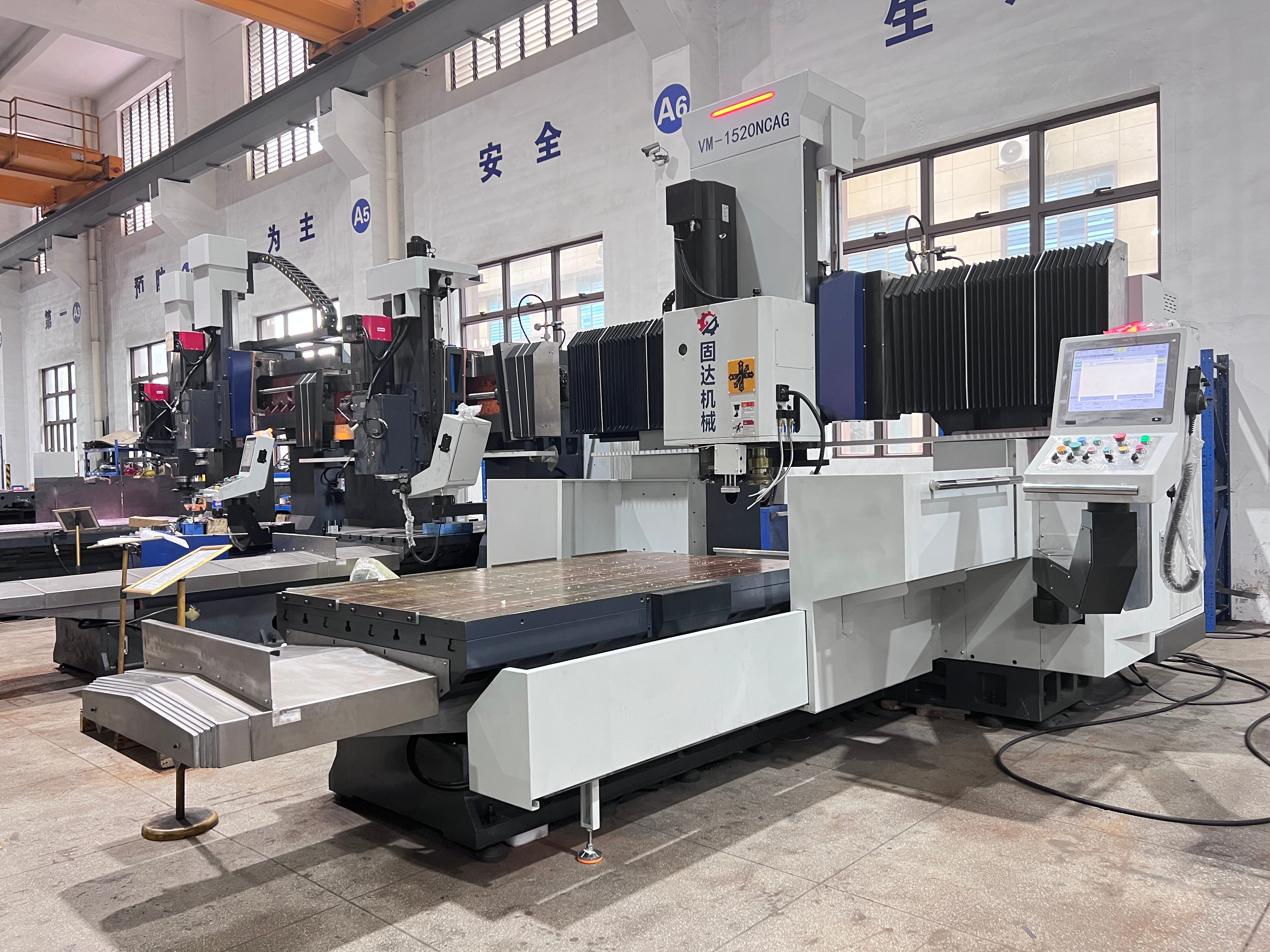
A CNC gantry milling machine can be a good fit when most of the work is large-surface milling. A gantry machining center may offer more automation when the process mixes milling, drilling, boring, tapping and automatic tool changing. The name on the machine matters less than the actual configuration.
Calculate the Real Machining Envelope
The plate dimension is not the same thing as the required machine travel.
Use:
Required X = plate length + fixture space + cutter overtravel
Required Y = plate width + fixture space + cutter clearance
For example, take a 4,000 mm plate that needs 150 mm of clamping space and 100 mm of cutter overtravel at each end:
4,000 + 150 + 150 + 100 + 100 = 4,500 mm
In that case, a nominal 4,000 mm X travel is not enough.
Workholding changes the answer. Strap clamps occupy the plate edge. Through-bolting depends on T-slot position. Magnetic workholding can leave more of the edge open, but it still has to provide enough holding force for the cut. See how to hold a large metal plate during machining for the main workholding options.
Check Column Clearance Separately
Y travel and the physical gap between the columns are not the same specification.
If the columns are 2,200 mm apart and the complete setup is 2,100 mm wide, that leaves only:
(2,200 − 2,100) ÷ 2 = 50 mm per side
That 50 mm still has to leave room for clamps, cutter bodies, inspection access and loading.
Look at the layout, not just the travel numbers:
- distance between columns
- table width
- spindle centerline limits
- ram travel
- guarding interference
- optional head interference
- tool-change position
If the plate fits but the fixture, cutter or required overtravel does not, the process does not fit the machine.
Have a part drawing? Send the maximum L × W × H, fixture layout and largest cutter. Those dimensions can be used to check the usable work envelope before choosing a machine size.
Check the Required Work EnvelopeCheck Table Load and Workholding
Use the complete setup when calculating table load:
Total table load = plate + fixture + supports + permanent workholding
Compare that number with the manufacturer's table-load limit and any restrictions on how the load can be distributed.
A 5-ton plate supported evenly across the table is not the same loading condition as 5 tons concentrated over a small area. Ask about concentrated-load limits and recommended support positions.
Also check:
- T-slot dimensions
- T-slot spacing
- fixture mounting positions
- access for clamps
- workpiece support points
The lifting system has to handle the whole suspended load too, including lifting beams, chains, magnets and other rigging.
Match the Spindle to the Cutter and Steel
Maximum kW and maximum rpm make nice brochure numbers. Neither should be used on its own to choose the spindle.
Compare:
- continuous power
- short-duration or peak power
- continuous torque
- maximum torque
- base speed
- power-versus-rpm curve
- torque-versus-rpm curve
- spindle interface
- maximum tool mass
The most useful point on those curves is the rpm where your production cutter actually runs.
Calculate Required Spindle Speed
Use the cutting speed recommended for the actual insert, cutter and material:
n = (1,000 × Vc) ÷ (π × D)
Where:
- n = spindle speed in rpm
- Vc = cutting speed in m/min
- D = cutter diameter in mm
Once you know the required rpm, check how much continuous power and torque the spindle has at that speed.
Material changes the cutting requirement. S45C/C45, stainless steel, pre-hardened mold steel and hardened alloy steel should not be treated as the same job. For S45C work, see the site's S45C machining guide.
Choose the Spindle Interface From the Tool List
Go through the actual tooling:
- largest cutter diameter
- tool mass
- tool overhang
- required bending stiffness
- toolholder availability
- automatic tool changer limits
A #50/BT50-class interface supports heavier tooling than smaller interfaces, but bigger is not automatically better. Cutter size, tool mass, overhang and cutting load should decide whether you actually need it.
Define Stock Removal Before Selecting the Machine
A light finishing pass and heavy roughing on the same plate are two very different loads.
For the roughing work, record:
- material grade
- hardness or delivery condition
- incoming blank condition
- stock allowance
- cutter diameter
- axial depth of cut
- radial engagement
- feed target
- number of roughing passes
Flame-cut edges, mill scale and uneven stock can make the cutting load jump around during roughing.
Saw-cut, flame-cut, forged and pre-machined stock may also need different preparation. See how to prepare steel blocks before CNC machining.
Calculate Chip Volume
A large plate can make a surprising amount of chips even when the depth of cut looks small.
Remove 5 mm from a 2,000 × 4,000 mm surface and the solid volume removed is:
2,000 × 4,000 × 5 = 40,000,000 mm³
That is 40 litres of solid material.
Once it becomes loose chips, it takes up even more space because of the air gaps between pieces.
Look at:
- chip channels
- screw or drag conveyors
- central conveyor position
- coolant drainage
- filter access
- areas below the gantry where chips can collect
If chip removal keeps stopping the job, the feed rate printed in the catalogue is no longer a realistic measure of production output.
Calculate the Vertical Stack
Z travel is not the same as maximum workpiece height.
Use:
Required vertical space = fixture + workpiece + holder + tool projection + approach clearance
Compare the total with the actual spindle-nose-to-table range.
Do this calculation with the longest tool in the process. A long drill, boring bar or angle head can set the vertical requirement even if the normal face mill has plenty of room.
Evaluate Structure and Guideways
Machine weight alone does not tell you what happens at the cutter tip.
Look at the full structural path:
- bed
- columns
- crossbeam
- ram
- spindle head
- guideway spacing
- axis-drive arrangement
- gantry synchronization
If heavy roughing matters, test heavy roughing. A light finishing cut on easy steel does not prove the machine can hold up under sustained production with a large cutter.
Linear Guides vs Box Ways
Guideway type by itself does not decide rigidity.
Roller linear guides use rolling contact and give low-friction axis movement. Box ways use sliding contact and are often chosen where damping is a design priority.
The real behavior still depends on guide size, spacing, preload, lubrication, bed stiffness and the direction of the cutting force.
Machine architecture also matters. A double-column machining center and gantry milling machine may accept similar workpiece sizes while moving different parts of the structure.
Separate Machine Accuracy From Part Accuracy
ISO 230-2 specifies methods for testing positioning accuracy and repeatability of numerically controlled machine-tool axes.[1]
That is useful information, but axis positioning is only one source of finished-part variation.
The part can also move because of:
- fixture movement
- tool deflection
- insert wear
- residual stress in the workpiece
- spindle thermal growth
- machine thermal growth
- measurement temperature
Always state the distance over which a tolerance applies. ±0.05 mm over 300 mm and ±0.05 mm over 4,000 mm are very different requirements.
For any quoted accuracy figure, ask how it was measured, over what distance, in what machine condition and under what measurement conditions.
Check Thermal Effects on Long Parts
ISO 230-3 covers machine-tool thermal effects caused by environmental temperature changes, rotating spindles and moving linear axes.[2]
NIST uses about 11.5 µm/m/°C for steel gauge-block examples and notes that the real coefficient depends on the material.[3]
Using that figure for a 4 m steel workpiece with a 2°C temperature change:
11.5 µm/m/°C × 4 m × 2°C = 92 µm = 0.092 mm
That number is the thermal expansion of this example workpiece. It is not a guaranteed machining error.
NIST research has also documented micrometer-level tool-to-workpiece thermal drift as machine temperature changes.[4]
For long-cycle precision work, look at:
- spindle cooling
- axis or ball-screw cooling where fitted
- temperature sensors
- thermal compensation
- warm-up procedure
- recommended ambient temperature range
Account for Residual Stress
When you remove material from a large plate, residual stress can be released and the plate can move.
Rolled, flame-cut, welded and heavily machined stock can all contain residual stress. How much it matters depends on the material history and the way stock is removed.
For tight flatness or parallelism, define:
- stock removed from each side
- roughing sequence
- intermediate measurement
- part relaxation where required
- material stress-relief condition
Check grade, hardness, flatness and delivery condition before locking in the machining route. See what to consider when buying large mold steel plates.
Check Tool Capacity, Coolant, and Setup Time
Tool Magazine
Count the tools from the real process, not from a rough estimate.
- required number of tools
- maximum tool diameter
- maximum tool length
- maximum tool mass
- adjacent-pocket restrictions
- total magazine load
A 30-pocket magazine does not always hold 30 usable tools. Large cutters may need neighboring pockets left empty.
Coolant
Compare coolant flow, pressure, filtration, chip separation and access for cleaning the tank.
Deep drilling and small internal coolant passages can need very different pressure and filtration from ordinary face milling.
Setup Time
Measure the whole production cycle:
loading + alignment + probing + cutting + tool changes + inspection + unloading
Probing can find plate edges, establish datums, detect angular setup error, update work offsets and inspect selected features. On low-volume large parts, cutting setup time can be more valuable than gaining a little extra rapid-traverse speed.
Check Loading and Installation
The crane has to carry the workpiece plus all lifting equipment.
- crane rated capacity
- rigging mass
- hook height
- guarding clearance
- loading direction
- operator visibility
- access to clamping points
For installation, use the foundation drawing for the exact machine configuration you are buying.
Confirm:
- installed machine mass
- foundation dimensions
- anchor positions
- floor loading requirements
- electrical supply
- compressed air
- coolant services
- maintenance clearance
After installation, verify leveling, axis condition, spindle run-in and compensation. The process is covered in the gantry milling machine alignment, leveling, and first-run procedure.
Check Safety Requirements Before Shipment
Before shipment, check guarding, door interlocks, emergency stops, chip containment, operator access, maintenance access and loading zones against the rules that apply in the destination market.
ISO 16090-1:2022 covers safety requirements for machining centres, milling machines and transfer machines used for metal cutting.[5] In the United States, OSHA 29 CFR 1910.212 requires guarding against applicable machine hazards and specifically includes milling machines in its point-of-operation requirements.[6]
Write the Acceptance Test Before Ordering
Decide what “acceptable” means before the machine is built. It is much harder to argue about test conditions after delivery.
Axis Positioning
State the axis, test length, measurement method and acceptable result. ISO 230-2 provides standardized methods for positioning and repeatability tests.[1]
Machine Geometry
Define the straightness, squareness, spindle geometry and other relationships that have a direct effect on the part.
Cutting Test
Fix the test conditions in advance:
- material grade
- blank dimensions
- cutter
- stock allowance
- machining program
- measurement method
- features to inspect
If you are buying the machine for heavy face milling, do not accept it based only on a light finishing pass with a small cutter.
Finished Test Piece
ISO 10791-7 specifies cutting tests for evaluating the accuracy of finished test pieces on applicable machining centres and compatible CNC milling or boring machines.[7]
On a production-style test piece, inspect the features that decide whether the real part will pass:
- flatness
- parallelism
- perpendicularity
- hole position
- bore diameter
- feature-to-feature distance
- surface finish where specified
Use the real part to define the acceptance test. Send the drawing, steel grade, stock allowance, cutter and critical tolerances before the machine specification is finalized.
Review a Test WorkpieceWhat to Require in the Supplier Quote
Give every supplier the same application data. Otherwise, you end up comparing different assumptions instead of different machines.
- maximum clamped L × W × H
- plate mass
- fixture and support mass
- material grade and hardness
- blank condition
- stock allowance
- largest cutter
- longest tool
- required operations
- critical tolerances and measurement lengths
- batch size
- expected daily machine hours
- part drawing or CAD file
Ask each quotation to state:
- usable machining envelope
- column clearance
- table load and load-distribution limits
- spindle power curve
- spindle torque curve
- tool diameter, length and mass limits
- coolant specification
- chip-removal configuration
- accuracy test method
- foundation requirements
- proposed acceptance test
If these values are missing, the quotes are not really being compared on the same technical basis.
Final Selection Checklist
| Question | Required Evidence |
|---|---|
| Does the complete setup fit? | Layout showing plate, fixture, cutter, and overtravel |
| Can the table carry it? | Total setup mass and permitted load distribution |
| Can the spindle make the cut? | Power and torque at actual cutting rpm |
| Does the longest tool fit? | Vertical stack calculation |
| Can chips leave the cutting zone? | Chip-volume estimate and conveyor layout |
| Can temperature affect the tolerance? | Thermal-control specification and test method |
| Can the machine hold the drawing? | Axis tests, geometry checks, and cutting test |
| Can the factory load the part? | Crane capacity and loading clearance |
| Can the machine be installed correctly? | Machine-specific foundation drawing |
FAQ
How much larger should the machine be than the steel plate?
Do not use a fixed percentage. Add the real fixture space and cutter overtravel to the plate size. A 4,000 mm plate that needs 150 mm of fixture space and 100 mm of overtravel at each end needs 4,500 mm of usable X travel.
How do I know if the spindle has enough torque?
First calculate the cutter's working rpm from cutter diameter and the tool manufacturer's cutting-speed data. Then look at continuous power and torque at that rpm. Maximum spindle kW and maximum rpm do not answer the question.
Why can a large steel plate move after machining?
Machining can release residual stress in rolled, flame-cut, welded or heavily machined stock. Uneven stock removal may change flatness or parallelism even when the machine itself positions accurately.
What should be included in a factory acceptance test?
Define axis positioning, relevant machine geometry, material, cutter, machining conditions, measurement method and finished-part limits before ordering. The cutting test should look like the real production process, not an easy demonstration cut.
Final Answer
Choose a CNC gantry milling machine around the complete workpiece setup, real cutting conditions and finished-part accuracy you actually need.
Before comparing price, verify the usable work envelope, table load, spindle torque at cutting rpm, vertical clearance, chip handling, thermal behavior and acceptance-test results.
Have a specific plate or mold base to machine? Send the drawing, clamped dimensions, setup weight, material, stock allowance, largest cutter and critical tolerances. Those details can be used to define the work envelope, spindle requirement and acceptance test before quotation.
Send Your Machining Requirements