

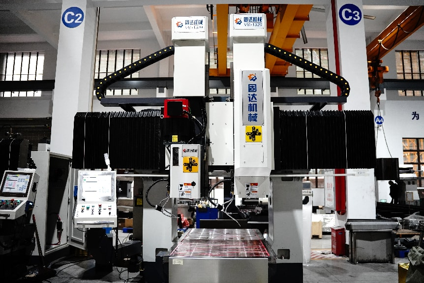
A double column machining center is usually the better fit when a large mold, die, plate, housing, or machine base can still be moved safely on the table. A travelling-bridge gantry milling machine becomes more practical when the workpiece is very long or heavy enough that keeping it stationary is an advantage. If both machines can hold the part, compare the usable opening, loaded workpiece weight, bridge span, ram and tool overhang, spindle torque, required setups, and thermal accuracy.
The names are not strict categories. ISO 8636-1 covers fixed-bridge machines with moving tables and fixed double columns, while ISO 8636-2 covers travelling-bridge machines with fixed tables.[1][2]
| Factor | Double Column Machining Center | Travelling-Bridge Gantry Milling Machine |
|---|---|---|
| Typical workpiece | Large molds, dies, housings, plates, machine bases | Long frames, heavy weldments, large aerospace and energy parts |
| Workpiece movement | Table and workpiece commonly move together | Workpiece commonly remains stationary |
| Very heavy parts | Table load and moving mass become important | Stationary workpiece is a major advantage |
| Very long parts | Possible, but table stroke increases total machine length | Long fixed-table layouts are easier to extend |
| Wide parts | Column opening limits setup width | Bridge span and stiffness become critical |
| Heavy steel cutting | Strong when fitted with a rigid ram and high-torque spindle | Strong when bridge, ram, spindle, and drives are sized for the load |
| Multiple-side machining | Angle or universal heads can reduce setups | Angle, universal, or 5-axis heads are common options |
Workpiece Size and Load
Do not select a machine from X/Y/Z travel alone. Check three different limits:
- Axis travel: how far the spindle or table moves.
- Clear opening: whether the complete setup passes between the columns and below the bridge.
- Usable machining space: the space left after adding clamps, fixtures, the tool holder, cutter, probe, and milling head.
A 2,000 mm-wide workpiece does not necessarily fit through a 2,100 mm column opening. If the clamps extend 60 mm from each side:
2,000 + 60 + 60 = 2,120 mm
The workpiece fits on the table, but the complete setup is 20 mm too wide.
A real LM-3227 double-column machining center shows why these numbers must be checked separately. Its detailed specification table lists a 2,100 × 3,000 mm table, 3,200 mm X travel, 2,760 mm Y travel, 1,200 mm Z travel, and 2,500 mm clear width between the columns.
Weight becomes important quickly with steel. A solid steel block measuring 2,000 × 1,500 × 500 mm has a volume of:
2.0 × 1.5 × 0.5 = 1.5 m³
Using a steel density of about 7,850 kg/m³:
1.5 × 7,850 = 11,775 kg ≈ 11.8 metric tons
An 8-ton die on a 1-ton fixture is already a 9-ton payload. The table itself may weigh several more tons on a large machine.
Also check how the weight is supported. Twelve tons spread across a large base is different from twelve tons resting on four small pads. A concentrated load can stress the table or distort the setup even when total weight is below the stated maximum.
Rigidity and Overhang
Rigidity should be judged at the cutter, not from machine weight alone. Cutting force passes through the tool, spindle, ram, bridge, columns, bed, fixture, and workpiece. Movement anywhere in that chain can appear on the finished part.
The main items to compare are:
- distance between the columns;
- bridge size;
- ram cross-section;
- ram extension during the actual cut;
- guideway spacing;
- spindle support;
- tool-holder size;
- tool overhang;
- fixture support.
Bridge width has a direct trade-off. A 4,000 mm opening gives 1,800 mm more capacity than a 2,200 mm opening, but the bridge also has to span a much greater distance. A wide bridge therefore needs enough section depth, guide spacing, and structural mass to control bending and twisting.
Ram and tool overhang can have an even larger effect. In a simple cantilever-beam calculation, deflection is proportional to the cube of unsupported length when load and section remain the same.
| Unsupported Length | Relative Theoretical Deflection |
|---|---|
| 300 mm | 1× |
| 600 mm | 8× |
| 900 mm | 27× |
A real machine ram is not a simple cantilever, so these are not machine-accuracy predictions. They show why a cut made with 300 mm of ram extension can behave very differently from the same cut near 900 mm extension.
Tool length adds to the problem. A 300 mm tool overhang is three times the length of a 100 mm overhang. On deep molds, the tool and holder may become the weak point before the machine structure does.
Guideways matter, but the name alone is not enough. Box ways provide large sliding contact areas and strong damping. Roller linear guides can carry large loads with lower friction and faster axis response. Compare rail size, rail spacing, block size, preload, and the structure under the guides rather than choosing from “box way” or “linear guide” alone.
The structural factors behind gantry machining rigidity and accuracy are therefore best checked as one system rather than as separate brochure features.
Moving Table vs Moving Gantry
A moving-table double column machine may move the table, fixture, and workpiece together. If the workpiece weighs 8 tons and the fixture weighs 1 ton, the machine is already moving 9 tons of payload before table weight is added.
High moving mass matters most when the toolpath has frequent starts, stops, and reversals. A part with 10,000 holes and short pockets places different demands on the axis drives from a mold that spends 12 hours making long, steady roughing passes.
A travelling-bridge machine leaves the workpiece stationary. This is useful for a 10 m, 15 m, or longer structure because the machine can move along the part without repeatedly moving the entire workpiece.
Large moving gantries have their own control requirement. On machines driven from both sides, the two sides must remain synchronized. If one side moves ahead of the other, bridge squareness can change.
For a large moving-gantry machine, ask for four specific answers:
- Is the gantry driven from one side or both?
- How are dual drives synchronized?
- How is bridge squareness checked?
- How is position measured over the full X travel?
Spindle for Steel or Aluminum
Heavy steel cutting and high-speed aluminum cutting need different spindle characteristics.
For steel roughing, compare:
- continuous torque at the rpm you will actually use;
- peak torque and its time limit;
- continuous motor power;
- tool interface;
- maximum cutter diameter;
- spindle bearing support.
A high maximum power number is not enough. A spindle can produce high peak torque for a short time without being able to hold the same load through hours of roughing.
The VM-2330NCA gantry milling machine is a useful heavy-cutting example. Its specifications list:
- 22 kW spindle motor;
- BT50 spindle taper;
- 50–500 rpm spindle range;
- 250 mm maximum cutter diameter;
- 14,000 kg worktable load;
- approximately 23,000 kg machine weight.
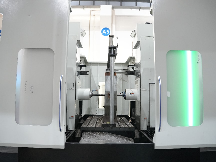
A high-speed machining spindle can be completely different. The GZXC-2000 5-axis machining center lists an HSK-63A spindle with a maximum speed of 12,000 rpm.
500 rpm and 12,000 rpm are not “bad” and “good” versions of the same spindle. The 500 rpm gear-driven configuration is aimed at large cutters and high torque. A 12,000 rpm spindle is better suited to operations where cutting speed and smaller tools matter.
For large aluminum structures, spindle speed is only part of productivity. Chip evacuation and axis acceleration can limit output before spindle power does.
Accuracy and Temperature
Separate machine positioning accuracy from actual part accuracy.
ISO 230-2 defines methods for testing CNC-axis positioning accuracy and repeatability.[3] Finished-part accuracy also includes tool bending, fixture movement, workpiece stress, cutting force, tool wear, and temperature. ISO 10791-7 uses machined test pieces to assess cutting accuracy, which is a different test from measuring an unloaded axis position.[4]
Temperature is especially important on large steel parts. NIST uses about 11.5 ppm/°C as an example coefficient of thermal expansion for steel, with variation depending on the exact material.[5] Using about 0.012 mm/m/°C gives an easy shop-floor estimate:
| Part Length | Temperature Change | Approx. Length Change |
|---|---|---|
| 1 m | 1°C | 0.012 mm |
| 2 m | 2°C | 0.048 mm |
| 4 m | 2°C | 0.096 mm |
| 5 m | 3°C | 0.180 mm |
A 4 m steel part that warms by only 2°C can therefore change length by about 0.096 mm. That is already larger than a ±0.05 mm dimensional tolerance.
Heat also changes the machine itself. NIST has measured micrometer-level tool-to-workpiece thermal drift in machine tools as internal temperatures change.[6]
Check whether the machine uses:
- spindle cooling;
- ball-screw cooling;
- temperature sensors;
- thermal compensation;
- controlled coolant or lubrication temperature.
ISO 10791-10 includes tests for distortion caused by room temperature, spindle rotation, linear-axis movement, and rotary motion.[7]
Five-Side vs Five-Axis
Five-side machining can save more time on a large rectangular part than full simultaneous five-axis machining.
A vertical spindle cuts the top. A 90° or universal head cuts the sides. The workpiece can remain in the same setup.
The LM-3227, for example, can be configured with a 90° angle milling head.
For a large part, one turnover can easily involve:
| Operation | Example Time |
|---|---|
| Crane preparation and lifting | 45 min |
| Cleaning and support setup | 30 min |
| Clamping | 45 min |
| Probing and datum setting | 60 min |
| Total | 3 hours |
These times are an example, not an industry standard. The calculation shows why avoiding one turnover can matter more than saving a few seconds on a tool change.
3+2 machining moves the rotary axes into a fixed angle and then performs normal three-axis cutting.
Simultaneous five-axis machining moves the rotary and linear axes together during the cut.
Use simultaneous five-axis when the surface or tool direction changes continuously. For a large mold base with flat top and side faces, a rigid 3-axis machine with a right-angle head may complete the job with less cost and complexity.
Cycle Time
Compare total job time, not only cutting speed.
Assume Machine A removes material 8% faster than Machine B, and Machine B needs 20 hours for roughing.
Machine A would need approximately:
20 ÷ 1.08 = 18.5 hours
Cutting-time saving:
20 − 18.5 = 1.5 hours
If Machine A then needs a 3-hour workpiece turnover to reach the sides while Machine B uses an angle head, the faster roughing machine loses its time advantage.
| Machine A | Machine B | |
|---|---|---|
| Roughing | 18.5 h | 20 h |
| Extra turnover | 3 h | 0 h |
| Total before equal side-cut time | 21.5 h | 20 h |
Large-part productivity is often won by eliminating handling, re-clamping, probing, and waiting rather than by increasing feed rate a few percent.
Chips, Tools, and Probing
Chip handling can limit production on a large machine.
If a mold blank loses 500 kg during roughing, the machine must remove roughly half a ton of chips. Aluminum creates even more chip volume for the same removed mass because aluminum is much less dense than steel.
Check:
- conveyor capacity;
- number and location of conveyors;
- bed flushing;
- coolant flow;
- filtration;
- areas where chips can collect around the workpiece.
Tool-magazine size also needs context. The GZXC-2000 provides a useful example:
- 40 tool pockets;
- 125 mm maximum tool diameter with neighboring tools installed;
- 220 mm diameter when the adjacent pocket is empty;
- 300 mm maximum tool length;
- 8 kg maximum tool weight.
A 40-pocket magazine therefore does not necessarily carry 40 oversized tools.
An on-machine probe is useful for datum setting, stock checking, and in-process measurements. It should not automatically be treated as a replacement for an independent measuring machine. ISO 230-10 covers performance testing of probing systems installed on CNC machine tools and separately notes that using the machine itself as a coordinate measuring machine involves additional accuracy and traceability issues.[8]
Loading and Installation
Machine selection should include the crane, floor, and workholding system.
A steel plate measuring 1.5 × 0.8 × 0.02 m has a volume of:
1.5 × 0.8 × 0.02 = 0.024 m³
At 7,850 kg/m³:
0.024 × 7,850 = 188.4 kg
Even a 20 mm-thick plate of this size is already a crane or lifting-device job in most workshops.
Before selecting the machine, check:
- maximum crane load;
- crane hook height;
- whether the hook can reach the center of the table;
- machine-door opening;
- floor load;
- foundation drawing;
- maintenance access around the machine.
A large plate also needs support close to cutting and clamping areas. Excessive clamp force on a thin plate can bend the part before machining even starts. The correct setup therefore changes with plate thickness, material, and support position; practical methods are covered in this guide to holding large metal plates during machining.
Foundation and leveling requirements should come from the exact machine drawing. The installation process for a large machine includes foundation checks, leveling, spindle checks, homing, and compensation rather than simply placing the machine on an available floor. These items are covered in the gantry milling machine setup procedure.
Applications
| Part | Example Size or Weight | Most Important Machine Requirement | Likely Choice |
|---|---|---|---|
| Steel mold or die | 2–4 m, several tons | Torque, rigidity, finishing accuracy, side access | Double column often fits well if table load is sufficient |
| Long welded frame | 6–15 m or more | Long X travel and stationary support | Travelling gantry often becomes more practical |
| Heavy machine base | 5–20+ tons depending on size | Flatness, straightness, hole location | Depends mainly on length and handling |
| Large aluminum structure | Several meters | High spindle speed, feed rate, chip removal | Large gantry layouts are useful when the part should stay fixed |
| Large plate | 1–4 m class | Support, flatness, clamp access | Either design can work |
| Deep die | Several hundred millimeters deep | Ram position and short tool reach | Choose the machine with the stiffer real cutting position |
For a 3,000 × 2,000 mm steel die weighing about 8 tons, a double column machine can be practical when the table can support the loaded fixture and the side features are reachable without another setup.
For a 12 m welded structure weighing 25 tons, keeping the workpiece fixed while the bridge travels along it can remove the need to accelerate the 25-ton part during every X move.
These are selection examples rather than category limits. A smaller or larger machine can use either architecture when its structure, load capacity, and working envelope are suitable.
RFQ and Acceptance
Give every machine supplier the same workpiece data:
| Item | Information to Provide |
|---|---|
| Workpiece | Maximum L × W × H and weight |
| Fixture | Size, weight, and clamp overhang |
| Material | Steel grade, cast iron, aluminum, titanium, etc. |
| Cutting | Largest cutter, typical rpm, roughing depth, deep cavities |
| Surfaces | Top only, five sides, angled features, or simultaneous 5-axis |
| Tolerance | Size, flatness, parallelism, perpendicularity, hole position |
| Surface finish | Required Ra or drawing requirement |
| Production | Parts per month and expected machining hours per part |
Then ask the supplier for values that match that job:
- clear column opening with the proposed machine configuration;
- loaded table capacity;
- ram extension at the deepest cut;
- continuous spindle torque at your cutting rpm;
- tool and angle-head clearance;
- guaranteed positioning accuracy and repeatability;
- thermal-control equipment;
- tool-magazine limits;
- chip-removal capacity;
- required foundation and crane access.
For a high-value machine, put the acceptance test into the purchase requirements. ISO 230-2 can be used for positioning and repeatability testing, while ISO 10791-7 provides finished-test-piece methods for cutting accuracy.[3][4]
The cutting test should resemble the real job. A 20-minute aluminum test cannot prove performance on a 12-hour steel roughing cycle. A short cold-machine test also cannot show how a long part behaves after several hours of spindle, axis, and coolant heating.
Finally
Choose from the complete workpiece setup, not the machine name. A 2,000 mm part can fail to fit through a 2,100 mm opening once two 60 mm clamps are added. A 2,000 × 1,500 × 500 mm steel block weighs about 11.8 tons. A 4 m steel part can change about 0.096 mm with only a 2°C temperature rise. For heavy steel, compare continuous torque and ram position; for very long or heavy parts, compare the cost of moving the workpiece against moving the gantry. If two machines can both hold the part, the machine requiring fewer setups while maintaining the required tolerance is usually the more productive choice.