

For steel plate milling, an electro-permanent chuck is usually the better choice when power-loss holding and reduced coil heating matter. A milling-rated electromagnetic chuck remains a valid option if it meets the cutting-load, temperature, and stopping requirements. Neither type is automatically stronger or better for thin plate; those decisions depend on the specific chuck, finished thickness, and contact conditions.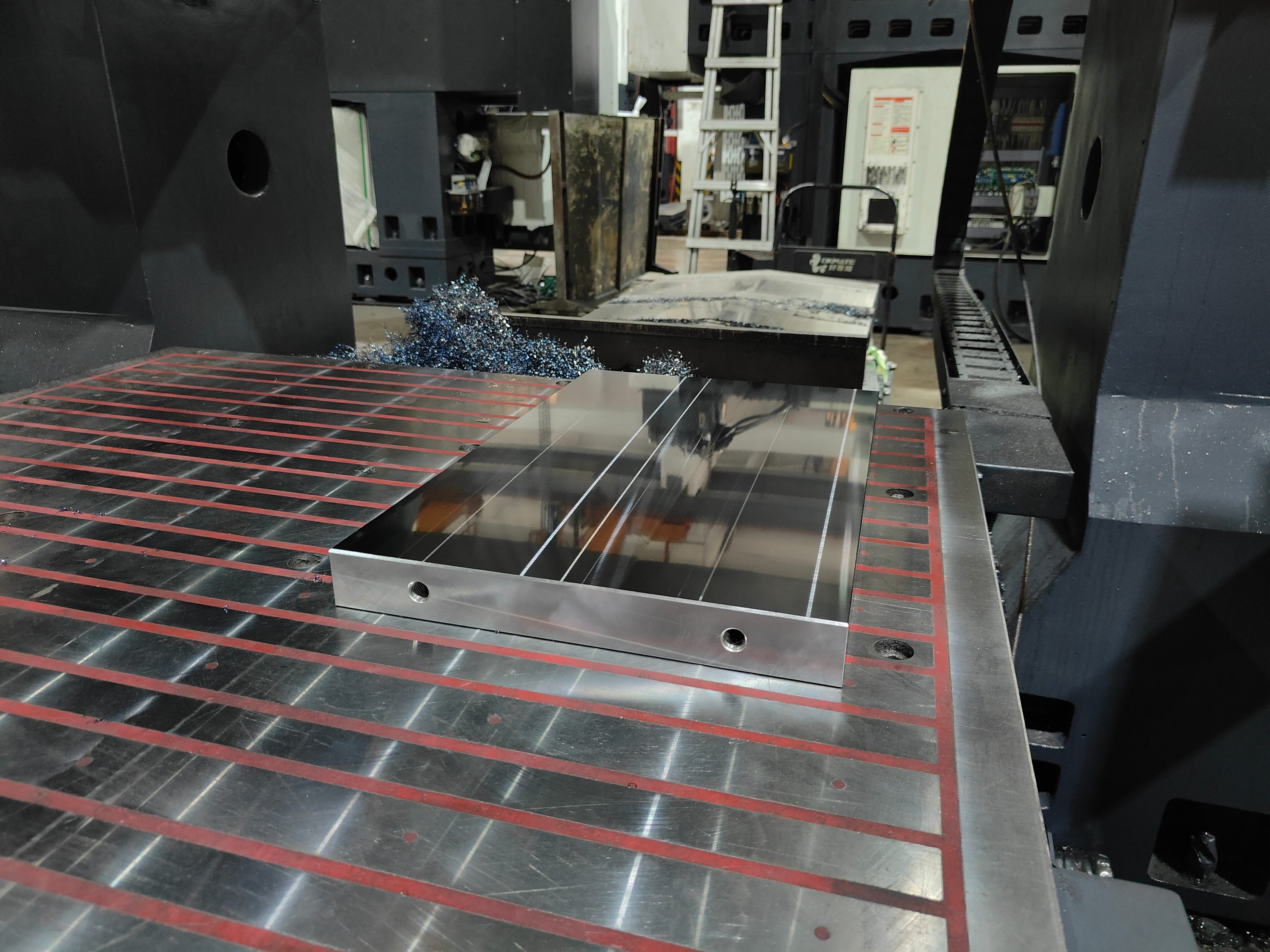
Key Differences
| Factor | Electro-Permanent Chuck | Electromagnetic Chuck |
|---|---|---|
| Power use | Electrical pulses switch the magnetic state. Holding requires no continuous coil power. | The coils need continuous power to maintain the intended field. |
| Power failure | The chuck retains its magnetic state after successful magnetization. | Holding force may decay. The installation must maintain adequate restraint until machine motion stops. |
| Heat during holding | No continuous excitation heating, though cutting and surrounding equipment still generate heat. | Coil heating must be included in the dimensional-stability check. |
| Heavy milling | Both require a milling-rated model and verification for the intended cutting loads. | |
| Thin plate | Pole layout, finished thickness, contact area, and support determine suitability. | |
Electro-permanent magnets use a pulse to change their magnetic state and retain that state without continuous excitation.[1] This does not mean a complete chuck system consumes zero electricity: controllers and switching cycles still use power.
Holding Force Is Not Cutting Capacity
As a calculation example, 100 N/cm² across 200 cm² gives 20 kN. That assumes the material, thickness, pole coverage, and contact match the stated test conditions. A 20 kN pull-off rating does not establish a 20 kN allowable side load or a safe depth of cut.
Side-load resistance also depends on friction and the stops used. Coolant, oil, overhang, and cutter position affect the result. Stops that resist sliding do not necessarily prevent an edge from lifting.
A 400 × 300 mm plate has a footprint of 1,200 cm². Underside pockets occupying 25% leave 900 cm² of geometric contact. Mill scale, trapped chips, or warping can reduce effective magnetic contact further. The resulting force loss cannot be calculated from the area percentage alone.
For a gantry milling setup for large steel plates, include the chuck and supports in the table-load and vertical-clearance calculations. Cutter access and overtravel must fit too.
Check the Final Thickness
If a plate starts at 20 mm and finishes at 8 mm, verify holding at 8 mm with the completed pockets and slots. A trial on the full-thickness blank does not cover the final cutting passes.
Thickness also changes stiffness. With material and other conditions unchanged, an ideal plate reduced from 10 mm to 5 mm has one-eighth of its original bending stiffness. More magnetic force cannot replace adequate support and may pull a warped plate flat during machining, only for it to spring back after release.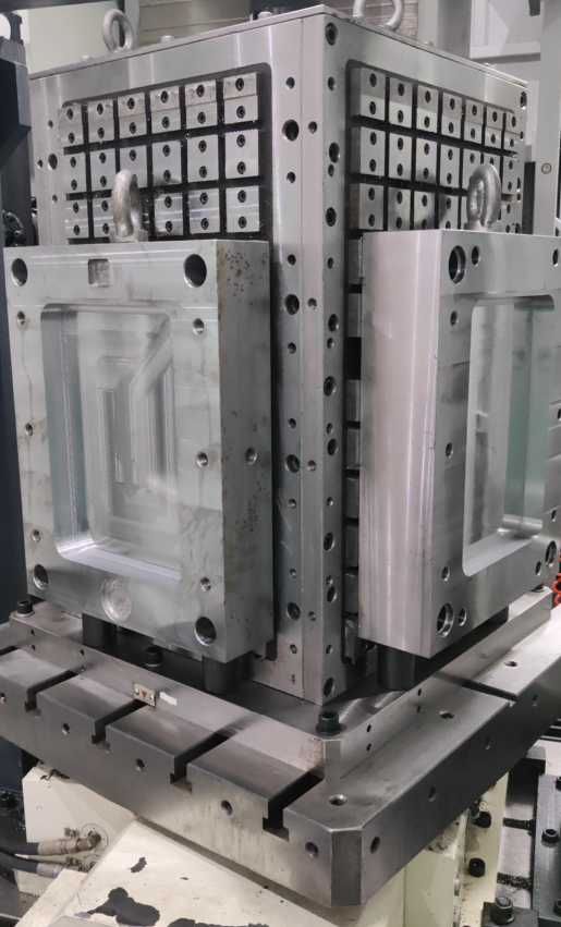
If the drawing requires free-state flatness within 0.05 mm, inspect the released part at the specified measurement temperature. A flatness reading taken while the plate is clamped does not establish compliance.
Material condition matters as well. Cold working can make otherwise weakly magnetic austenitic stainless steels, including 304 and 316, locally magnetic.[2] A hand magnet sticking to an edge is not evidence of adequate holding for milling.
Measure Heat Before Claiming Better Accuracy
NIST gives 11.5 × 10⁻⁶/°C as a typical steel expansion coefficient; the actual value depends on the material.[3] Using that value, a freely expanding 500 mm plate grows by 0.02875 mm after a uniform 5°C rise.
A plate measuring 500.000 mm at the reference temperature would then measure about 500.029 mm. Without temperature correction, it would exceed a 500.000 ± 0.020 mm inspection limit. This is a thermal-expansion example, not a measured error for either chuck.
When comparing chucks, keep the toolpath and cooling conditions the same. Record plate, chuck, and coolant temperatures. Separate the plate’s expansion from spindle and axis thermal drift before attributing a dimensional improvement to the chuck.
Upgrade Cost and Payback
The figures below are worked examples, not market averages. The electricity and setup-time cases are separate calculations.
| Item | Assumptions | Result |
|---|---|---|
| Existing coil-power cost | 0.5 kW × 2,000 hours/year × CNY 1/kWh | CNY 1,000/year |
| Electricity-only payback | CNY 30,000 upgrade cost; assumes all the above electricity cost is saved | 30 years, before accounting for the new system’s electricity use |
| Setup-time value | 4 minutes saved × 1,500 parts/year × CNY 200/hour | 100 hours, valued at CNY 20,000/year |
| Payback from realized time savings | CNY 20,000 benefit minus CNY 5,000 added annual costs; CNY 30,000 investment | CNY 15,000 net annual benefit; 2-year simple payback |
Measure setup time from cleaning and locating through magnetic switching and unloading. Neither chuck type guarantees a four-minute saving. Count the saved hours as a financial benefit only when they support extra production, reduce overtime, or remove another cost.
What to Specify Before Ordering
- Workpiece: For mold steel blanks, state the grade, heat treatment, starting and finished dimensions, underside geometry, and measured warping.
- Cutting conditions: Supply cutter diameter, axial and radial depth of cut, feed per tooth, toolpath, overhang, and support layout.
- Installed cost: Include the chuck, controller, pole extensions, locating hardware, installation, and machine interlocks.
- Power-loss response: Specify clamping feedback, demagnetization interlocks, fault-detection time, and spindle and feed stopping times. Any backup supply must cover the assessed stopping sequence.
- Acceptance trial: Record magnetic settings, cutting parameters, part movement, and dimensions after release. Add residual-magnetism limits and measurement methods where the next operation requires them.