

because a CNC machine is not physically the same temperature all day. The spindle warms up, ball screws and motors generate heat, coolant temperature moves, fixtures expand, and the part itself may be warmer when you measure it. On a 500 mm aluminum dimension, even a uniform 1°C change works out to roughly 0.0115 mm. That is already larger than the total tolerance on some precision parts.
The important thing is not to label every changing dimension as “thermal drift” and start moving offsets. First work out what is moving: the machine, the tool, the fixture, the part, or simply the measurement.
ISO 230-3 treats machine-tool thermal error in much the same way. It separates environmental temperature effects, spindle heating, linear-axis effects, and thermal changes related to rotary motion rather than treating temperature as one single error source.[1]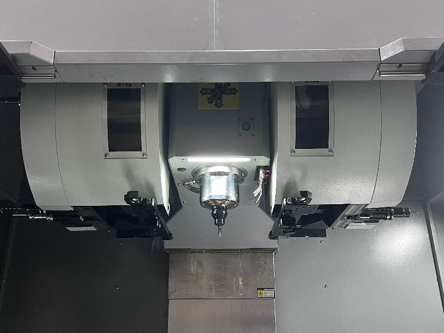
How Much Can Temperature Change a Dimension?
The basic calculation is simple:
Dimensional change = original length × coefficient of thermal expansion × temperature change
Take a 500 mm aluminum part. Using about 23 µm/m·°C:
500 mm × 23 µm/m·°C × 5°C = 57.5 µm ≈ 0.058 mm
For a 500 mm steel part at roughly 11–12 µm/m·°C:
500 mm × 11–12 µm/m·°C × 5°C ≈ 0.028–0.030 mm
NIST's Gauge Block Handbook gives aluminum at about 24 µm/m·°C and steel gauge-block materials around 10.6–11.5 µm/m·°C near room temperature, so these are reasonable numbers for estimating the scale of the problem.[2]
Another way to look at it is per degree:
| Length | Aluminum, per 1°C | Steel, per 1°C |
|---|---|---|
| 100 mm | ≈ 2.3 µm | ≈ 1.1–1.2 µm |
| 300 mm | ≈ 6.9 µm | ≈ 3.3–3.6 µm |
| 500 mm | ≈ 11.5 µm | ≈ 5.5–6.0 µm |
| 1,000 mm | ≈ 23 µm | ≈ 11–12 µm |
That table is useful because it puts “a few degrees” into perspective. A 500 mm aluminum dimension changing uniformly by only 2°C changes by about 0.023 mm. At 5°C, it is nearly 0.058 mm.
| Temperature Change | 500 mm Aluminum | 500 mm Steel |
|---|---|---|
| 1°C | ≈ 0.0115 mm | ≈ 0.0055–0.0060 mm |
| 2°C | ≈ 0.023 mm | ≈ 0.011–0.012 mm |
| 3°C | ≈ 0.0345 mm | ≈ 0.0165–0.018 mm |
| 5°C | ≈ 0.0575 mm | ≈ 0.0275–0.030 mm |
These are free-expansion calculations, not predicted machining errors. A real CNC process is more complicated. The machine may be warm while the part is cool, one side may be hotter than the other, the fixture may restrict movement, and the control may already be compensating for part of the machine's thermal growth.
Material grade matters too. Do not assume every steel behaves exactly the same. Different mold steels used for CNC machining have different properties, so the correct material data should be used when temperature becomes part of the tolerance calculation.
Uneven Heating Is Often the Bigger Problem
The easy calculation assumes the whole part changes temperature evenly. In the real world, that is often not what happens.
Imagine a plate that is 20°C on one side and 28°C near the freshly machined area. The hot side wants to grow more. Instead of simply becoming longer, the plate can bow or twist. A bore may move slightly out of shape. A flat surface may stop being flat.
The machine structure can do something similar. If one side of the column is warmer than the other, the column may tilt by a tiny amount. At the tool tip, especially with a long spindle or tool assembly, that small angle can turn into a measurable positional error.
ISO 230-3 includes both expansion/contraction and angular deformation when evaluating thermal effects in machine-tool structures.[3]
This is why a single room-temperature reading does not tell you everything. Sunlight on one side of the machine, an HVAC vent, an open shop door, piles of hot chips, a nearby heat source, or cold coolant repeatedly hitting one area can all matter.
Spindle Warm-Up
If several unrelated tools start changing in roughly the same Z direction after the machine starts, the spindle is a sensible place to look first.
Inside a vertical machining center, the spindle bearings, motor, lubrication system, and cutting process all generate heat. As those parts warm, the physical position of the tool center point can move relative to the workpiece. This is why spindle thermal-error studies measure both temperature and displacement rather than temperature alone.[4]
You may see it as a change in pocket depth, shoulder height, face location, counterbore depth, spotface depth, or tool-length measurement.
But there is no universal rule saying a hot spindle always grows straight down in Z. Machine design matters. Bearing arrangement, preload, cooling, motor location, and spindle housing design all affect how it moves. On some machines the main change is axial. On others there may also be smaller X/Y movement or a slight tilt.
Load matters as well. Running at 12,000 rpm in air is not the same thermal condition as cutting hard at 12,000 rpm. Heavy cutting puts more load into the motor and bearings and adds heat to the tool, coolant, chips, and workpiece.
That is why the OEM warm-up cycle should be followed first, but a warm-up timer by itself does not prove a tight-tolerance process is ready.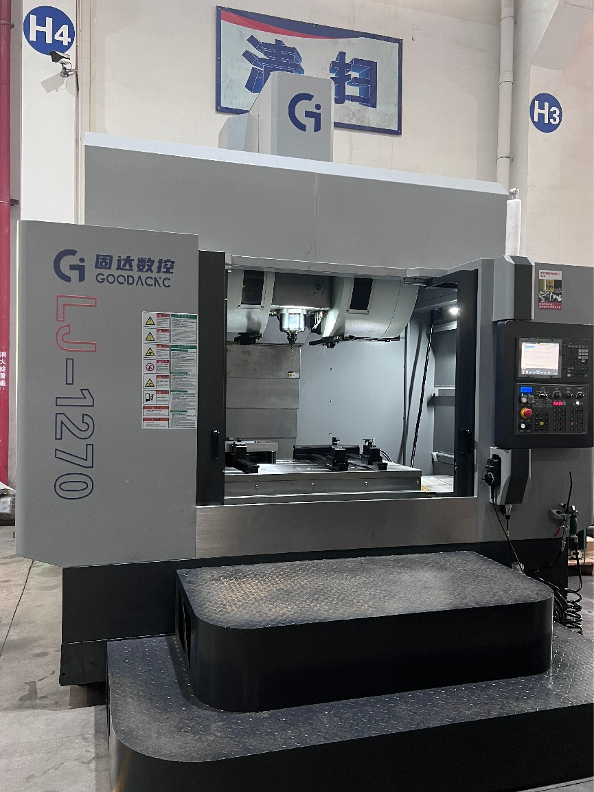
Here is a simple example:
| Time | Total Z Change | Change Since Last Check |
|---|---|---|
| Cold | 0 µm | — |
| 10 min | +8 µm | +8 µm |
| 20 min | +13 µm | +5 µm |
| 30 min | +16 µm | +3 µm |
| 45 min | +17 µm | +1 µm |
| 60 min | +17.5 µm | +0.5 µm |
Those numbers are only an example. What matters is the shape of the trend. The machine moved 8 µm in the first 10 minutes, then only another 0.5 µm during the final 15 minutes. It is settling down.
Whether that final 0.5–1 µm matters depends on the job. On a ±0.05 mm feature, probably not. On a ±0.003 mm feature, perhaps it does.
Long stops can reset part of that thermal condition. So can a job change. A machine that has been cutting steel at 3,000 rpm all morning may start moving toward a different thermal condition when the next job runs aluminum at 15,000 rpm with much more axis travel and coolant flow.
This is also why the first part of the morning can be misleading. If you cut it cold, adjust it exactly to nominal, then let the machine continue warming, you may end up correcting the same dimension again half an hour later.
Ball Screws and Axis Heat
The spindle gets most of the attention, but the feed axes generate heat too.
A typical axis may contain a servo motor, ball screw, ball nut, support bearings, guideways, and lubrication. Repeated rapid moves and acceleration create friction and heat. The ball screw can then change length slightly.
Ball-screw thermal deformation is a known source of positioning error. Experimental studies show that heat around the screw, nut, bearings, and drive system can change axial dimensions and affect positioning stability.[5]
The error does not have to be the same everywhere along the axis. A program that spends all day moving through a small part of X travel can heat the system differently from a program that uses the full stroke.
Linear scales help because they measure table or slide position more directly instead of relying only on motor rotation and ball-screw movement. Still, they cannot fix everything. The scale may say X is correct while the spindle has shifted, the machine structure has tilted, the fixture has expanded, or the part itself is warm.
This is one reason different horizontal and vertical machining-center layouts do not necessarily show the same thermal behavior. The structure and the position of the spindle, table, axes, and workholding are different.
Coolant Temperature
Coolant can quietly become a big part of the problem because it touches so much of the machining system.
It collects heat from the tool, chips, cutting zone, workpiece, fixture, table, pumps, and machine enclosure. If the tank starts at 19°C and reaches 26°C later in the day, that is a 7°C change in one of the main heat-transfer systems around the part.
For perspective, if a 500 mm aluminum part itself changed uniformly by the full 7°C:
500 mm × 23 µm/m·°C × 7°C ≈ 80.5 µm = 0.081 mm
That does not mean a coolant increase of 7°C automatically creates 0.081 mm of machining error. The part will not necessarily follow the coolant temperature exactly. It simply shows that a 7°C change is large enough to take seriously on long aluminum parts.
Another common mistake is assuming colder is always better. If very cold coolant repeatedly hits one area of a warmer fixture or machine, it can create a temperature difference across the structure. For precision work, stable coolant is often more useful than extremely cold coolant.
Also make sure you know which temperature you are looking at. A machine may have several separate systems:
- Cutting coolant around the tool and part;
- spindle chiller for the spindle or spindle housing;
- axis cooling on machines with cooled ball screws or motors;
- hydraulic oil for clamps, pallets, and actuators.
Writing “coolant = 24°C” in a troubleshooting sheet is not enough if you do not know which circuit that number came from.
Fixtures Move Too
The fixture is easy to overlook because it feels like a solid reference. It is still metal, though, and it still changes size with temperature.
Consider a 500 mm aluminum workpiece located on a 500 mm steel fixture. With a uniform 5°C rise:
- Aluminum free expansion: about 57.5 µm
- Steel free expansion: about 27.5–30 µm
- Difference: roughly 28–30 µm over 500 mm
A real clamped assembly will not simply slide by 30 µm. Friction, clamps, locators, stiffness, and geometry all restrict movement. What the calculation tells you is that the aluminum and steel are trying to move by different amounts. That can change contact force, build stress, move a datum, or show up later when the part is unclamped.
On large mold blocks, this matters even more because a datum error can carry into later operations. The same issue comes up in six-sided mold block machining, where a reference-face or locating error can follow the part from one setup to the next.
Hydraulic clamping adds another variable. As oil temperature changes, viscosity and leakage behavior can change too. The fixture may not behave exactly the same cold and hot even when the pressure setting on the system has not been touched.
The Part May Be Changing, Not the Machine
This is especially easy to miss with aluminum.
Take a 400 mm aluminum housing measured at 30°C and then again at 20°C:
400 mm × 23 µm/m·°C × 10°C = 92 µm = 0.092 mm
That is not a small number. NIST explains that dimensional measurements are referenced to 20°C and that temperature correction matters when measurements are made away from that condition.[6]
A freshly machined part may also have a warm inside and a cooler outside. A deep bore can stay warm while coolant cools the surface. One side of a plate may have just been rough-machined while another side has already settled.
So one surface-temperature reading does not always tell you what the entire part is doing.
You can also work backward from the tolerance. Suppose you wanted free thermal expansion alone to stay below 0.005 mm over 500 mm.
For aluminum:
5 µm ÷ 11.5 µm/°C ≈ 0.43°C
For steel:
5 µm ÷ 5.5–6 µm/°C ≈ 0.83–0.91°C
Those are not recommended shop-temperature specifications. They simply show how quickly the available temperature range becomes small once the part gets long and the tolerance gets tight.
Thin parts have another problem: they can move because of stress as well as temperature. If the part changes mainly after unclamping, look hard at clamping distortion and residual stress. If it continues moving while it sits, thermal equalization may be involved too.
Heat-treatment and stress-relief history can also change how mold steel behaves after material removal. That is a material problem, not something that should automatically be fixed with a machine offset.
Make Sure the Measurement Is Real
Before saying the machine moved 5 µm, make sure your measurement method can actually see 5 µm reliably.
A digital display reading to 0.001 mm looks precise. That does not mean the complete measurement system—gauge, operator, part, temperature, alignment and measuring force—can repeat within 0.001 mm.
Suppose you measure the same stable feature five times:
50.002 / 49.999 / 50.003 / 50.001 / 49.998 mm
The spread is 0.005 mm.
That is not a formal uncertainty study, but it tells you something useful straight away: this measurement setup is not a good way to prove a 0.002 mm machine drift.
NIST notes that uncertainty in part temperature and the coefficient of thermal expansion contributes to dimensional-measurement uncertainty when measurements are made away from the 20°C reference condition.[7]
Infrared thermometers need a little caution as well. Shiny metal is not always easy to measure accurately with IR because emissivity affects the result. NIST research on machining thermography identifies emissivity as an important source of uncertainty in infrared temperature measurement of metal-cutting processes.[8]
On-machine probing has its own limitation. The probe measures a relationship between itself and the reference surface. If the spindle, table, probe, fixture and reference are all changing slightly, the number you see is the combined result.
That does not make probing unreliable. It simply means the reference and thermal condition have to be understood. The same applies to automatic measurement during multi-face machining.
Look at What Kind of Error Changed
This is one of the quickest ways to narrow the problem.
Size means things like bore diameter, slot width or pocket width. If size moves but position stays stable, look first at the cutter, runout, wear, tool deflection, compensation, cutting conditions and part temperature.
Position means hole location, pocket center, shoulder Z location or distance from a datum. If several unrelated features move together, the spindle, axis, fixture datum or machine thermal state becomes more likely.
Form means flatness, parallelism, squareness, cylindricity and similar geometry. Form errors often point toward uneven heating, clamping, residual stress or angular movement in the machine.
Here is a simple example. A nominal 20.000 mm bore measures 20.001 mm in the morning and 20.002 mm at noon. The size changed only 0.001 mm.
But its X position moves from 100.000 mm to 100.012 mm.
That is a 0.012 mm positional shift with almost no diameter change. Simple cutter wear is no longer the obvious explanation. Now the datum, axis, fixture, spindle or machine thermal condition deserves more attention.
This is also why parallelism and squareness in milling need to be checked separately from basic size. A part can measure the right width and still be geometrically wrong.
A Quick Diagnosis
| What You See | Check First |
|---|---|
| Several tools move similarly in Z after startup | Spindle/head thermal movement |
| Only one cutter changes feature size | Wear, runout, deflection, holder |
| Only one tool keeps moving in Z | Tool pullout or holder condition |
| X/Y position moves after repeated axis travel | Feed-axis thermal behavior |
| Dimensions follow coolant temperature | Coolant, workpiece, fixture, table |
| Part changes after cooling | Workpiece temperature |
| Error returns after a long stop | Warm-up and thermal history |
| Error depends on where the axis is positioned | Axis or geometric behavior |
| Thin part changes after release | Clamping or residual stress |
| Several dimensions suddenly jump | Datum, fixture, probe or mechanical fault |
Four questions usually narrow things down quickly:
- One tool or several? One tool points toward the cutter or holder. Several tools moving together point more toward the machine, spindle, axis, datum or fixture.
- Size, position or form? Different error types usually have different causes.
- Does the part change after cooling? If it does, workpiece temperature is involved.
- Does a fixed reference move without cutting? If it does, machine thermal movement is part of the problem.
Run a Simple Test Before Changing Offsets
You do not need a laboratory to get useful data. You do need consistency.
Record the machine's idle time before startup, room temperature, cutting-coolant temperature, spindle or chiller temperature if available, spindle runtime, major RPM changes, reference position, critical dimensions, offset changes and long stops.
Then do a no-cut test. Use a qualified reference artifact, tooling ball or another stable reference. Measure the relationship between the spindle/probe and that reference as the machine warms without removing material.
If that relationship moves, the machine's thermal state is involved. If it stays stable but the machined part moves, look harder at the tool, cutting force, fixture, material and part temperature.
Try not to change several things at once. If coolant temperature rises at the same time that the part grows, that is useful evidence—but it is not proof that coolant caused all of the change. The spindle, axes and part may all be warming at the same time.
After a few normal days, you should have a rough baseline. For example, a machine that repeatedly shifts 8–10 µm during warm-up and then settles into the same range is very different from one that shifts 3 µm today and 35 µm tomorrow under similar conditions.
The exact numbers are machine-specific. The repeatability of the pattern is what matters.
Not Everything Is Thermal Drift
A dimension that changes with time can have plenty of other causes.
- Tool wear: usually shows up on one cutter or one type of feature first.
- Tool pullout: can look almost exactly like progressive Z drift. Check holder grip, taper or collet cleanliness, tool overhang and axial cutting load.
- Tool deflection: changing cutting force can change finished size without the machine position moving.
- Fixture movement: a vise, pallet, locator or stop can shift on its own.
- Residual stress: especially common on large or thin plates after heavy stock removal.
- Chip under a locator: one small chip can create more error than the thermal movement you are trying to measure.
- Probe or gauge error: contamination, calibration, stylus condition or poor repeatability can create a false trend.
- Mechanical faults: backlash, loose couplings, bearing problems, damaged holders or crash damage can all be mistaken for thermal drift.
Five-Axis Machines Add Another Layer
On a five-axis machine, A, B or C axes can warm as their motors, bearings and rotary structures run. That can change the rotary center or angle slightly relative to the spindle and workpiece.
The effect gets larger as the tool or cutting point moves farther from the rotary center.
For example, an angular error of only 0.001° over a 300 mm distance gives a lateral displacement of roughly:
300 mm × tan(0.001°) ≈ 0.0052 mm
That 0.001° is only a geometry example; it is not being presented as a typical five-axis thermal-error value. It simply shows why very small angular changes can matter when the lever arm is long.
ISO 230-3 includes thermal-distortion testing for rotary motion of machine components, so rotary heating should not be treated as nothing more than another XYZ offset.[9]
Use Compensation Only After You Understand the Trend
There are really four ways to deal with thermal error: generate less heat, remove heat, keep the process thermally stable, or compensate for a known repeatable shift.
Compensation is useful when the error is predictable. It is much less useful when the underlying problem is random, mechanical, or coming from the workpiece rather than the machine.
Thermal compensation models also need to work across changing shop conditions. Research using year-round spindle data shows why a model that performs well under one ambient condition may not behave exactly the same across a wider temperature range.[10]
And keep the tolerance budget in mind. If the drawing allows ±0.010 mm, the one-sided allowance from nominal is 10 µm.
| Thermal Shift | One-Sided Allowance | Allowance Used |
|---|---|---|
| 2 µm | 10 µm | 20% |
| 5 µm | 10 µm | 50% |
| 8 µm | 10 µm | 80% |
If thermal movement has already used 8 µm, you have consumed 80% of the one-sided allowance before adding tool wear, cutting force, fixture variation, material movement and measurement error. So “the thermal drift is smaller than the tolerance” is not a very useful test of process capability.
When the Drift Is Not Normal
Normal thermal movement is usually fairly smooth and repeatable under similar conditions. Sudden or very different behavior deserves more attention.
Watch for jumps instead of gradual movement, loss of repeatability, much larger drift than the machine normally shows, new spindle noise, chiller or lubrication alarms, new axis-position dependence, or unexpected probe and scale behavior.
Possible causes include spindle-bearing changes, cooling-system faults, lubrication problems, pump failures, ball-screw issues, loose fixtures, probe faults, scale problems, damaged holders or crash damage.
Your best comparison is usually not another machine in another shop. It is the same machine's own normal behavior.
Conclusion
A few degrees can be enough to matter. Over 500 mm, aluminum changes by about 0.0115 mm per 1°C of uniform temperature change; common steel is roughly 0.0055–0.0060 mm per 1°C. But a changing CNC dimension does not automatically mean the spindle is growing. Check whether the error is size, position or form, whether one tool or several are affected, whether the part changes after cooling, and whether a fixed no-cut reference moves during warm-up. Just as important, make sure the measurement system can actually resolve the change you are chasing. A smooth, repeatable thermal shift can often be stabilized or compensated. Random jumps, a rapidly changing baseline, or a machine that suddenly behaves differently should be treated as a troubleshooting problem—not another reason to keep moving offsets.