

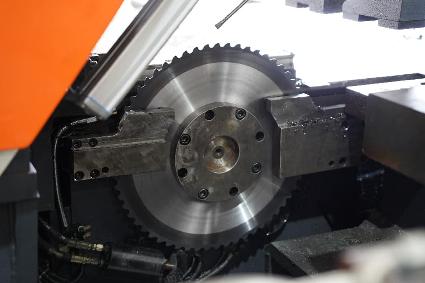
Answer: Circular saw blade deflection occurs when the blade is pushed sideways during cutting. If the blade moves before touching the steel, check the blade mounting, flanges, spindle, and runout. If it moves only under load, check the teeth, feed, speed, chip removal, heat, and blade stiffness. If the kerf moves after the blade passes, check the workpiece support, clamping, and internal stress.
This guide covers industrial circular saws used to cut solid mold steel. HSS cold saws, carbide circular saws, and dry-cut TCT saws use different speeds, feeds, and cooling methods. Use the machine and blade manuals as the final source for operating limits.
For example, the PCS-800NC flat plate circular saw uses a carbide blade for tool steel and alloy steel. Its product page lists a maximum load of 2,000 kg, a raw-material length of 2,500 mm, and an adjustable cutting feed of 0–460 mm/min. These figures also show why machine load capacity, support, and feed control must be checked separately from motor power.
Safety: Stop and isolate the machine before touching the blade, spindle, flanges, guards, clamps, guides, or workpiece. Release or control electrical, hydraulic, pneumatic, and stored mechanical energy. Do not run the machine with a cracked blade, broken tooth, loose block, damaged guard, or unknown blade speed rating.
Check When the Error Starts
The point where the error begins usually gives the fastest clue to the cause.
| When the Problem Starts | Check First |
|---|---|
| The blade moves before touching the steel | Blade plate, flanges, arbor fit, spindle runout, and bearings |
| The blade jumps when it enters the steel | Entry feed, tooth pitch, chipped teeth, surface scale, and clamping |
| The cut starts straight and curves with depth | Blade stiffness, dull teeth, chip packing, heat, and feed per tooth |
| The error appears near the end of the cut | Cut-off support, block sag, rotation, lifting, and kerf closure |
| Several good blades cut toward the same side | Spindle, saw-head travel, vise alignment, guides, and machine frame |
| The kerf moves after the blade has passed | Internal stress, support height, self-weight, and clamp distortion |
Find What Is Moving
The term “blade deflection” is often used for several different faults. Separate them before changing the cutting settings.
Blade runout is movement that exists before cutting. Axial runout is side-to-side movement of the blade plate. Radial runout is a change in the tooth-tip radius as the blade turns.
Cutting deflection occurs when the blade runs normally without load but bends after entering the steel. Common causes are high side force, dull teeth, poor chip removal, low blade stiffness, and a kerf that pushes against the blade.
Blade vibration is rapid movement between both sides. It often leaves repeated waves or tooth marks instead of one steady taper. Loose guides, tooth impact, unstable spindle speed, or machine resonance may cause it.
Workpiece movement occurs when the steel slides, lifts, twists, sags, or closes around the blade. A straight blade can still produce an angled cut if the block moves during cutting.
Confirm the Mold Steel Condition
Mold steel grades do not cut in the same way. Hardness matters, but carbide content, heat treatment, scale, weld repairs, and section size also affect cutting force and blade wear.
The following values are typical website-listed material conditions. They are useful for comparing materials, but the actual hardness should be confirmed from the material certificate or by testing.
| Steel | Typical Supplied Condition | Typical Hardness | Cutting Note |
|---|---|---|---|
| P20 / 1.2311 | Prehardened | About 28–36 HRC | Normally easier to saw than hardened hot-work or cold-work steel |
| P20+Ni / 1.2738 | Prehardened | About 33–38 HRC | Large sections need stable blade support and controlled feed |
| H13 / 1.2344 | Soft annealed | Maximum about 229 HB | Heat-treated H13 must not use the same setup as annealed H13 |
| D2 / 1.2379 | Annealed | Maximum about 255 HB | High carbide content can cause strong abrasive tooth wear |
The difference between supplied and heat-treated material is important. Annealed H13 or D2 may be sawable with suitable industrial equipment, while fully hardened material can be outside the approved range of the same blade.
Before cutting, confirm:
- Steel grade and delivery condition
- Actual hardness
- Block width, height, and length
- Flame-cut, welded, or locally hardened areas
- Surface scale
- Required cut accuracy
- Available machining allowance
The wider AsiaTools mold steel range can be used to compare plastic-mold, hot-work, cold-work, and stainless mold steels.
Choose the Right Blade
The blade must match the steel grade, hardness, section size, machine, spindle speed, feed system, and cooling method.
Check these blade details:
- Blade diameter and arbor size
- Blade-body thickness
- Kerf width
- Tooth material and coating
- Tooth count and pitch
- Rake and clearance angles
- Gullet size
- Maximum safe rpm
- Approved material and hardness range
An HSS cold saw blade normally runs at a controlled cutting speed and often uses cutting fluid. A carbide-tipped industrial blade can cut harder material and support higher output, but it needs a rigid spindle, stable feed, and firm clamping.
Some TCT blades are designed for dry cutting. Do not add liquid coolant unless both the blade and machine manufacturers approve it.
A tooth pitch that is too fine can fill the gullets before the teeth leave a deep block. The packed chips are then compressed or cut again. A pitch that is too coarse leaves fewer teeth in the steel, increasing the load and impact on each tooth.
Do not select a circular saw from motor power alone. Blade diameter, cutting depth, clamp travel, spindle rigidity, table load, feed control, and material support are also important. See How to Choose a Circular Saw Machine for Steel Blocks for a wider equipment checklist.
Check Blade Stiffness
A thin blade makes a narrow kerf and removes less steel, but it also bends more easily.
For a simple flat plate, bending stiffness changes roughly with the cube of thickness. This gives the following comparison:
| Thickness Change | Calculation | Approximate Stiffness Change |
|---|---|---|
| 10% thicker | 1.10³ = 1.331 | About 33% more stiffness |
| 15% thicker | 1.15³ = 1.521 | About 52% more stiffness |
| 20% thicker | 1.20³ = 1.728 | About 73% more stiffness |
These figures explain only the basic effect of thickness. A rotating saw blade is also affected by diameter, flange size, body shape, slots, temperature, spindle speed, and guides.
A thicker blade is not automatically better. It makes a wider kerf, creates more chips, needs more motor power, and produces more heat. Use only blade sizes approved for the machine.
Inspect the Teeth
Clean the blade before inspection. Steel stuck to a tooth can look like a chipped tip, while packed chips can hide cracks and wear.
Inspect the full blade under good light for:
- Missing or cracked tips
- Small chips on the cutting edges
- Rounded teeth
- Unequal tooth height
- Wear on only one side
- Steel stuck to the tooth face or sides
- Cracks near tooth seats, slots, or the arbor hole
- Uneven grinding marks after resharpening
A small, even wear band behind the cutting edge is normal. A wider wear band increases cutting force and heat.
One-sided polishing usually means the blade is rubbing against one side of the kerf or is mounted out of line.
Chipped edges may be caused by heavy entry impact, excessive feed per tooth, loose clamping, hard scale, or unsuitable tooth pitch.
Steel buildup on a tooth may point to poor lubrication, high heat, unsuitable speed, restricted chip flow, or a dull edge.
After resharpening, check tooth height, side clearance, tooth shape, remaining blade diameter, and runout. A blade can be sharp and still pull sideways if the teeth were ground unevenly.
Calculate Feed per Tooth
Feed and spindle speed must be adjusted together. Lowering rpm without lowering linear feed increases the amount of steel removed by each tooth.
For an automatic machine, nominal feed per tooth is:
fz = Vf / (n × z)
fz= nominal feed per tooth in mm/toothVf= linear feed in mm/minn= spindle speed in rpmz= number of teeth
Calculation example: A machine feeds at 150 mm/min. The blade runs at 50 rpm and has 100 teeth.
fz = 150 / (50 × 100) = 0.03 mm/tooth
The result is a calculation example, not a recommended setting. The approved feed per tooth depends on the blade, tooth shape, steel grade, hardness, and section size.
Feed may be too high when:
- Motor load rises quickly
- Teeth chip
- Vibration increases
- Chips become very heavy or uneven
- The cut curves soon after entry
Feed may be too low when:
- The blade makes fine metallic dust
- Tooth faces become polished
- A high rubbing sound develops
- Cutting time becomes unusually long
- Heat increases without clear chip formation
Reducing feed is not always the correct response to heat. If the teeth are already rubbing, a lower feed may create more heat.
Calculate Cutting Speed
Cutting speed is calculated as:
Vc = π × D × n / 1000
Vc= cutting speed in m/minD= blade diameter in mmn= spindle speed in rpm
Calculation example: A 400 mm blade runs at 20 rpm.
Vc = π × 400 × 20 / 1000 = 25.1 m/min
If the same 400 mm blade runs at 30 rpm:
Vc = π × 400 × 30 / 1000 = 37.7 m/min
Increasing spindle speed from 20 to 30 rpm raises cutting speed by 50%. It also changes heat, tooth contact frequency, and the feed needed to maintain the same feed per tooth.
The same rpm produces a higher cutting speed on a larger blade. Never exceed the blade’s rated rpm. Use the supplier’s cutting range for the actual steel and blade.
Read the Chips
Chip shape gives useful clues, but it should not be used alone.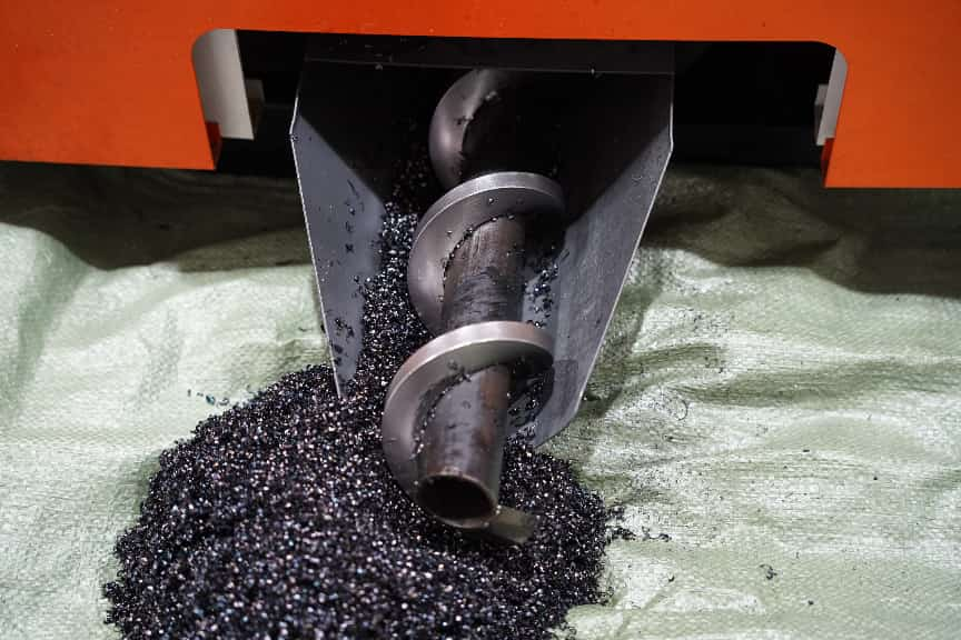
| Chip Condition | Possible Meaning |
|---|---|
| Consistent formed chips | Cutting may be stable |
| Fine dust | Rubbing, dull teeth, low feed, or recutting packed chips |
| Heavy broken chips | High tooth load, impact, or interrupted cutting |
| Chips stuck to the teeth | Heat, poor lubrication, dull edges, or restricted chip flow |
| Chips packed inside the gullets | Pitch too fine, deep engagement, or poor chip removal |
Dark chips may mean higher heat, but chip color is also affected by steel grade, coating, cutting fluid, and time in contact with the blade.
Control Cutting Heat
The teeth and outer rim receive direct heat from the cut. Dull teeth, rubbing, packed gullets, side contact, poor lubrication, and excessive tooth load can heat the blade unevenly.
New local blue or brown marks may show overheating, especially when they appear together with side rubbing or a loss of blade flatness. Color alone is not a temperature measurement. Some HSS blades already have dark oxide coatings.
For a wet-cut machine, check:
- Coolant concentration
- Pump flow
- Nozzle direction
- Filter condition
- Chip contamination
- Whether fluid reaches the cutting zone
If the machine uses two-sided delivery, check both sides. Do not add liquid coolant to a dry-cut system or run a wet cold saw dry without approval.
Clean the Blade Mount
A small chip trapped behind the blade can tilt it. A mounting error of only a few hundredths of a millimeter near the flange can produce a more visible movement near the blade edge.
Before installation, clean and inspect:
- Spindle locating surface
- Inner and outer flanges
- Blade bore
- Approved reducing ring
- Washer and bolt
Do not use extra washers to correct alignment. Do not hand-grind a precision flange. Tighten the blade with the method and torque given by the machine manufacturer.
Measure Runout in the Correct Order
Do not measure only the installed blade. Use a dial indicator and check each part separately:
- Measure the bare spindle locating diameter.
- Measure the flange face near its working outer area.
- Install the blade and measure the blade body near the outer edge.
- Avoid teeth, slots, burrs, and damaged areas.
- Remove, clean, reinstall, and measure again.
If the reading changes greatly after every installation, inspect for dirt, damaged contact faces, a loose adapter, or inconsistent tightening.
When the mounting design allows the blade to be repositioned, compare the location of the high point:
- If the high point turns with the blade, the blade contributes to the error.
- If the high point stays in the same machine position, the spindle or flange contributes.
- If it moves only part of the way, more than one source may be involved.
Do not reposition a blade that uses fixed drive pins, keys, or a required mounting direction.
There is no single runout limit for every blade. Limits vary with blade diameter, blade type, machine design, cutting depth, and required accuracy. Use the written limit supplied for the exact blade and machine.
Check Support and Clamping
The main block and cut-off piece must remain stable until the blade has fully left the steel.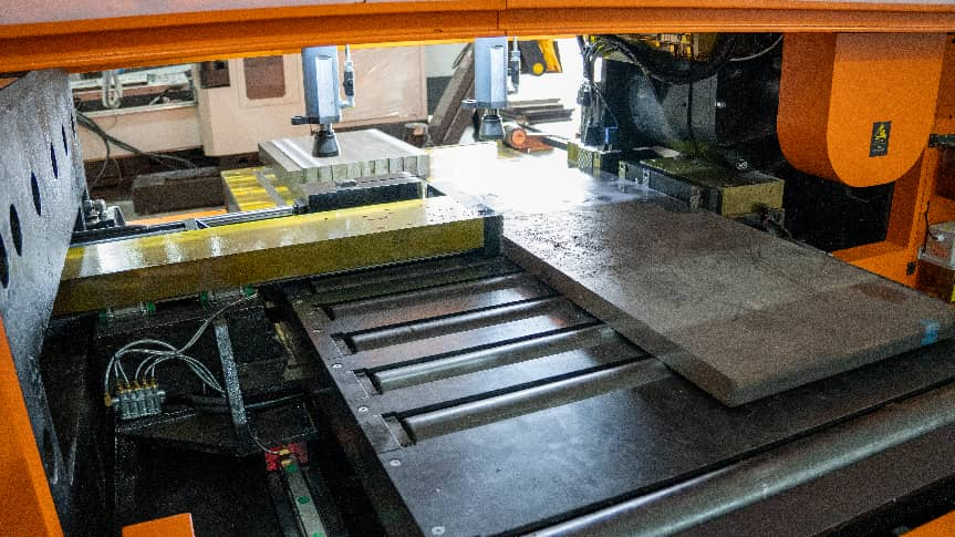
Check that:
- Support rollers are level with the saw table.
- A long block does not sag before cutting.
- The cut-off piece cannot drop or rotate.
- The support position does not force the kerf closed.
- The clamp is close enough to the cut.
- The clamp face contacts clean, solid steel.
- Hydraulic pressure remains stable.
- Multiple clamps operate in the correct order.
More clamp pressure is not always better. Excessive pressure can bend a narrow plate or twist a block that is not sitting flat.
During a test cut, draw matching reference marks across the workpiece and machine table. Any change between the marks confirms that the block moved.
Check Internal Stress
Internal stress can come from forging, rolling, heat treatment, welding, flame cutting, or earlier machining. When the block is cut, the kerf may open, close, or twist.
Check whether:
- The kerf changes width after the blade passes.
- The two cut sides continue moving after the machine stops.
- The same movement occurs at different positions in the block.
- Changing the block direction changes the result.
- The block loses straightness after rough cutting.
A closing kerf does not prove internal stress by itself. Low supports, self-weight, excessive clamp force, and an uneven table can produce the same sign.
Possible corrections include moving the supports, turning the block, changing the cutting order, rough cutting before final sizing, and leaving more machining stock. See the guide to mold block allowance and stress-relief planning .
Wire EDM removes blade force and avoids blade pinching, but it does not stop the steel from moving when internal stress is released.
Calculate Machining Allowance
The remaining stock must cover the planned finish machining, saw-cut error, setup variation, and surface cleanup.
Example:
- Required final machining stock: 1.5 mm
- Measured saw-cut deviation: 0.4 mm
- Setup and cleanup allowance: 0.3 mm
Required stock = 1.5 + 0.4 + 0.3 = 2.2 mm
In this example, leaving only 1.5 mm would not be enough because part of the stock would already be used to remove the saw error.
The allowance must be set for the actual block, heat-treatment route, and final machining process. The article on six-side machining of mold steel blocks explains why reliable reference faces are needed before later CNC work.
Check Hard Areas
A local increase in cutting load may come from flame-cut edges, weld repairs, heat-affected zones, hardened surfaces, heavy scale, or uneven material structure.
Possible signs include:
- Motor load rises at the same cutting depth.
- Teeth are damaged at the same position.
- The cutting sound changes suddenly.
- Local scoring appears on the cut face.
- The blade begins moving at the same point in repeated cuts.
Unexpected sparks do not prove a hard spot. Sparks can also come from side rubbing, broken teeth, scale, trapped chips, or contact with a machine part.
When hardness testing is needed, remove the scale, prepare a smooth surface, take several readings, and compare the suspected area with a normal area. One portable reading on a rough surface is not enough.
Check the Machine
If different verified blades cut toward the same side, inspect:
- Spindle and bearing condition
- Flange alignment
- Saw-head side play
- Guide wear
- Rail straightness
- Vise position
- Table flatness
- Drive belts or gears
- Hydraulic or servo feed stability
A falling spindle speed does not always mean the motor is too small. A dull blade, high feed, hard steel, packed chips, belt slip, bearing drag, low voltage, or a feed-control fault can produce the same result.
Compare spindle speed, motor current, feed pressure, and cutting time with a known good cut.
Set an Internal Warning Level
A workshop can use cutting time and average motor load as early warning values. These are internal control levels, not universal machine limits.
For example, if a verified process normally completes a cut in 100 seconds:
| Cutting Time | Change from Baseline | Suggested Action |
|---|---|---|
| 100–105 seconds | 0–5% | Continue monitoring |
| 110 seconds | 10% | Inspect teeth, chips, coolant, and material condition |
| 115 seconds | 15% | Stop and find the cause before increasing feed |
The same method can be used for average motor load. Only compare cuts made with the same steel, section size, blade, speed, feed, and support arrangement.
Use This Check Order
- Stop the machine and record where the error started.
- Check whether the blade moves during free rotation.
- Confirm the steel grade, condition, hardness, and section size.
- Inspect every tooth and the blade body.
- Clean the mount and measure spindle, flange, and blade runout.
- Check the supports, clamps, and cut-off piece.
- Calculate feed per tooth and cutting speed.
- Check chips, heat, coolant, and side rubbing.
- Check machine alignment if several blades fail in the same direction.
- Change one condition at a time and repeat the test.
Use the Quick Diagnosis Table
| Symptom | Likely Cause | Best Check |
|---|---|---|
| Blade moves before cutting | Dirty flange, bent blade, spindle or bearing error | Measure the spindle, flange, and blade separately |
| Blade jumps at entry | High entry feed, coarse pitch, hard scale, or loose block | Inspect the first teeth and mark the block position |
| Cut curves only at high feed | High tooth load, dull teeth, or low blade stiffness | Compare motor load, chips, and tooth edges |
| Cut becomes worse with depth | Heat, chip packing, low stiffness, or closing kerf | Check chips, side marks, coolant, and kerf movement |
| Fine dust replaces normal chips | Rubbing, dull teeth, low feed, or chip recutting | Inspect the tooth edges and calculate feed per tooth |
| One side of the blade is polished | Side rubbing, mounting error, or unequal tooth clearance | Check runout, alignment, and kerf pressure |
| Kerf closes behind the blade | Stress release, poor support, or clamp distortion | Measure the kerf after the blade passes |
| Several blades cut in the same direction | Machine or workholding error | Use a verified blade and inspect the machine references |
| Error appears near completion | Cut-off piece drops or rotates | Watch the support during final separation |
| Motor load rises from cut to cut | Blade wear, chip packing, cooling loss, or harder steel | Compare current, cutting time, chips, teeth, and hardness |
Measure the Cut Error
Record both the total error and the error per 100 mm of cutting depth. This makes it easier to compare blocks of different sizes.
Example: The top-to-bottom error is 0.30 mm over a cutting depth of 200 mm.
Normalized error = 0.30 / 200 × 100 = 0.15 mm per 100 mm
A total error of 0.30 mm has a different meaning on a 50 mm block than on a 300 mm block. Recording error per 100 mm gives a clearer comparison.
Measure:
- Squareness: angle between the cut and a clean reference face
- Straightness: bowing through the depth of the cut
- Taper: size difference between the top and bottom
- Kerf width: actual width compared with the expected blade kerf
- Repeatability: difference between repeated cuts
Repeat the Test Cut
Use at least two cuts when checking a correction. Three consecutive cuts are better when setting a new production baseline.
For example:
| Test Cut | Top-to-Bottom Error | Error Direction |
|---|---|---|
| Cut 1 | 0.18 mm | Right |
| Cut 2 | 0.21 mm | Right |
| Cut 3 | 0.19 mm | Right |
The average error is about 0.193 mm, and the difference between the highest and lowest readings is 0.03 mm. Because all three cuts move in the same direction, the problem is repeatable rather than random.
Keep these conditions unchanged during the test:
- Steel grade and hardness
- Block dimensions and orientation
- Blade model and tooth count
- Spindle speed and feed
- Coolant or lubrication
- Clamp pressure
- Support positions
Record the Process Data
A useful test record should include:
- Steel grade and hardness
- Block width, height, and length
- Blade diameter, thickness, tooth count, and condition
- Spindle speed in rpm
- Calculated cutting speed in m/min
- Linear feed in mm/min
- Calculated feed per tooth in mm/tooth
- Motor load and cutting time
- Runout before cutting
- Chip condition
- Top, middle, and bottom cut measurements
Do not use one tolerance for every job. The acceptable error must leave enough material for surface cleanup, setup variation, and final machining.
When the sawed surface cannot meet the final flatness or finish requirement, later surface grinding of the mold steel may be needed.
Prevent the Problem from Returning
- Create a known-good setup for each common steel grade and section size.
- Record normal runout, motor load, cutting time, chips, and cut error.
- Track total cut area instead of recording only the number of cuts.
- Record every sharpening and repaired tooth.
- Record the blade diameter after sharpening.
- Clean the flanges and spindle at every blade change.
- Inspect resharpened blades before production.
- Follow the blade maker’s break-in procedure.
Some cold-saw manufacturers recommend slower feeding during the first three or four cuts with a new or resharpened blade. This is a manufacturer-specific practice and should not be treated as a rule for every blade.
Stop the Machine When
- The blade, tooth seat, or arbor area is cracked.
- A tooth breaks.
- The blade touches the guard or another machine part.
- The workpiece moves out of the clamp.
- The blade binds or the motor stalls.
- Severe vibration begins.
- The guard does not work correctly.
- Runout or cut error exceeds the approved limit.
- The cut error approaches the available machining allowance.
Do not restart a blade trapped in the steel until the machine is isolated and the cause of the binding has been found.
Change the Cutting Process When Needed
Circular sawing may not be practical when the steel hardness is outside the blade range, the section is too deep for stable cutting, the kerf repeatedly closes, or the required accuracy is beyond the machine’s repeatable ability.
A band saw may be more suitable for large or mixed sections with lower kerf loss. A rigid circular saw is normally better for fast, repeated block cutting. See Circular Saw vs Band Saw for Steel Cutting .
Wire EDM removes blade force but does not stop stress-release movement. Milling or grinding may still be required for final size, flatness, and surface finish.
Technical References
- Scotchman Cold Saw Blade Basics — blade pitch, flange cleaning, coolant, blade coatings, clamping, and break-in guidance
- OSHA Machine Guarding: Saws — machine guarding, energy isolation, and operator safety
- AsiaTools PCS-800NC — an industrial carbide circular saw for tool steel and alloy steel
Conclusion
Blade deflection should be checked with measurements, not guesswork. Start by finding whether the blade moves before contact, during the cut, or after the kerf opens. Calculate cutting speed and feed per tooth, inspect every tooth, clean the flanges, and support both sides of the block. Record motor load, cutting time, runout, and error per 100 mm of depth. Use at least two test cuts, or three when setting a new baseline. A repair is successful only when the cut repeats within the required machining allowance without rising load, side rubbing, chipped teeth, or workpiece movement.