

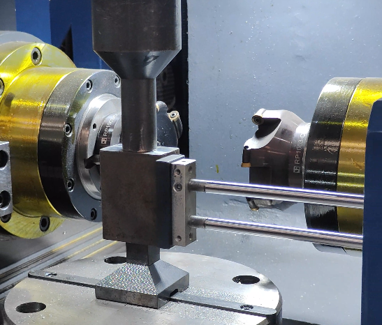
Answer: The correct hydraulic clamping pressure is the lowest practical operating pressure that keeps the mold steel block from sliding, lifting, or rotating, while staying below the pressure that bends or marks the block. Calculate the required clamp force first, convert it into pressure with the actual clamp data, and then verify the setting by measuring movement and springback on the real workpiece.
Use this order: cutting load → solid stops → supports → clamp force → hydraulic pressure → shop-floor test.
Pressure cannot correct weak stops, chips under the block, poor support, or a clamp placed over a thin section. Flat, square stock is easier to locate and support. See why mold steel blocks need six-side milling or review custom mold steel blocks for CNC machining.
All figures below are calculation examples, not default settings for every machine or fixture.
Pressure Is Not Clamp Force
A pressure gauge shows oil pressure in the circuit. Clamp force also depends on piston area, clamp geometry, internal friction, arm length, and pad contact.
F = P × A
- F = theoretical cylinder force
- P = hydraulic pressure
- A = effective piston area
When pressure is in MPa and area is in mm², 1 MPa equals 1 N/mm². A 500 mm² piston at 20 MPa produces:
F = 20 × 500 = 10,000 N = 10 kN
| Piston Area | 10 MPa | 15 MPa | 20 MPa | 25 MPa |
|---|---|---|---|---|
| 300 mm² | 3.0 kN | 4.5 kN | 6.0 kN | 7.5 kN |
| 500 mm² | 5.0 kN | 7.5 kN | 10.0 kN | 12.5 kN |
| 700 mm² | 7.0 kN | 10.5 kN | 14.0 kN | 17.5 kN |
Theoretical piston force before spring, linkage, arm-length, seal-friction, and pad-contact losses.
| Conversion | Value |
|---|---|
| 1 MPa | 10 bar |
| 20 MPa | 200 bar |
| 1 MPa | About 145 psi |
| 1 kN | About 225 lbf |
For a commercial swing, lever, or link clamp, use the manufacturer’s pressure-force chart. For a custom hydraulic lever clamp, output may be estimated by:
Fc = P × A × R × η
At 20 MPa, 500 mm², a 0.85 mechanism ratio, and 0.90 efficiency:
Fc = 20 × 500 × 0.85 × 0.90 = 7.65 kN
The ratios are examples. Use the rated output for the actual hydraulic clamping system.
If the rod side is pressurized, use the annular area:
A = π(D² − d²) ÷ 4
Find the Cutting Load
Use the highest realistic machining load, not the average spindle-load display. Check horizontal force, upward force, drilling thrust, entry impact, interrupted cutting, torque, and force acting above the support plane.
Data can come from tooling calculators, CAM simulation, measured spindle torque, a dynamometer, a calibrated load cell, or validated results from a similar job.
If cutting torque is known:
Ft ≈ T ÷ r
For 240 N·m torque and a 40 mm cutting radius:
Ft = 240 ÷ 0.04 = 6,000 N
This does not include axial force, vibration, or tool-entry impact. A hydraulic pressure sensor measures clamping pressure, not cutting force, unless the complete fixture has been calibrated.
Cutting depth, feed, tool diameter, steel hardness, and overhang change the load. See CNC roughing parameters for P20 and H13 mold steel.
Use Solid Stops
Hydraulic clamps should keep the block seated. Solid stops should carry the main horizontal cutting load.
Weak load path: tool force → block → friction → fixture.
Better load path: tool force → block → solid stop → fixture.
Check the stop body, contact area, mounting bolts, thread engagement, fixture-plate thickness, and base mounting. Unless analysis or testing proves the load split, size the stop for the full horizontal design load.
Calculate Friction
Fr = μN
N = Fh ÷ μ
If friction must carry 4 kN, the assumed coefficient has a large effect:
| Assumed Friction Coefficient | Horizontal Load | Required Normal Force |
|---|---|---|
| 0.08 | 4 kN | 50.0 kN |
| 0.12 | 4 kN | 33.3 kN |
| 0.18 | 4 kN | 22.2 kN |
Calculation examples only. These are not standard friction values for wet or dry mold steel.
Oil, coolant, polishing, oxide scale, chips, and pad material can change friction. Effective normal force is approximately:
Neffective = Fclamp + W − Fup
Apply the Safety Factor
There is no single factor for every fixture. Use the clamp maker’s guidance, company rules, load accuracy, cutting conditions, and the result of a possible failure.
Apply the factor once to the full external load. For a 9 kN cutting force and a factor of 2:
Fdesign = 9 × 2 = 18 kN
Do not multiply only the friction part while leaving the stop at its original load.
Check Lift and Rotation
An upward cutting force reduces friction and may lift one corner. For a 2 kN upward force and a factor of 2:
Fup,design = 2 × 2 = 4 kN
A horizontal force above the support plane creates a tipping moment:
M = F × h
For 8 kN acting 180 mm above the support plane:
M = 8,000 × 0.18 = 1,440 N·m
If the clamp-force line is 400 mm from the tipping edge:
Flift = 1,440 ÷ 0.4 = 3,600 N
Add this reaction to any upward tool force acting at the same time. Do not assume several clamps share the load equally.
Place Clamps and Supports
Place each main clamp above or close to a rigid support. Avoid clamping the middle of a long unsupported span.
Deflection ∝ F × L³ ÷ (E × I)
| Unsupported Span | Relative Bending |
|---|---|
| 100 mm | 1.00 |
| 150 mm | 3.38 |
| 200 mm | 8.00 |
Relative values from the simplified L³ relationship, with all other conditions unchanged.
For a rectangular section:
I = b × t³ ÷ 12
| Effective Thickness | Relative Bending Stiffness |
|---|---|
| 40 mm | 100% |
| 30 mm | 42.2% |
| 20 mm | 12.5% |
Relative values based on t³, using 40 mm as the reference.
A pressure that works on a solid blank may bend the block after a deep cavity is cut. Fixed supports establish the datum; adjustable or hydraulic supports should only fill gaps and support the existing position.
Check Pad Contact
Average pad pressure is:
p = F ÷ A
For a constant 10 kN clamp force:
| Pad Size | Contact Area | Average Contact Pressure |
|---|---|---|
| 20 × 20 mm | 400 mm² | 25.0 MPa |
| 25 × 25 mm | 625 mm² | 16.0 MPa |
| 30 × 30 mm | 900 mm² | 11.1 MPa |
Actual edge pressure may be higher if the pad is tilted or does not make full contact.
Avoid narrow pads over cavity roofs, cooling holes, thin ribs, sharp edges, polished surfaces, or finished sealing faces.
Set the Pressure
For a custom lever clamp:
P = Fc ÷ (A × R × η)
For 10 kN, 550 mm², R = 0.85, and η = 0.90:
P = 10,000 ÷ (550 × 0.85 × 0.90) = 23.8 MPa
This is about 238 bar or 3,450 psi. For a commercial clamp, use its rated pressure-force chart.
- Calculated pressure: theoretical result
- Minimum verified pressure: lowest tested setting that prevents movement
- Operating pressure: production setting with margin
- Maximum pressure: highest setting that keeps deformation acceptable
The working pressure cannot exceed the lowest-rated clamp, hose, fitting, valve, or manifold.
Worked Example
| Input | Value |
|---|---|
| Actual horizontal cutting force | 9 kN |
| Actual upward force | 1.8 kN |
| Safety factor | 2 |
| Assumed friction coefficient | 0.12 |
| Number of clamps | 4 |
| Piston area per clamp | 600 mm² |
| Mechanism ratio | 0.90 |
| Estimated efficiency | 0.90 |
A validated analysis is assumed to show that the stop carries 7 kN and friction carries 2 kN before the safety factor.
Horizontal design load = 9 × 2 = 18 kN
Stop design load = 7 × 2 = 14 kN
Friction design load = 2 × 2 = 4 kN
Normal force for friction = 4 ÷ 0.12 = 33.3 kN
Upward design load = 1.8 × 2 = 3.6 kN
Total downward clamp force = 33.3 + 3.6 = 36.9 kN
Force per clamp = 36.9 ÷ 4 = 9.23 kN
P = 9,230 ÷ (600 × 0.90 × 0.90) = 18.99 MPa ≈ 190 bar
If friction had to carry the full 18 kN horizontal load:
N = 18 ÷ 0.12 = 150 kN
Total clamp force = 150 + 3.6 = 153.6 kN
P = 38,400 ÷ (600 × 0.90 × 0.90) = 79 MPa ≈ 790 bar
The 790 bar result shows why solid stops should carry the main cutting load.
Change Pressure by Machining Stage
Roughing: Use strong stops, close supports, and a pressure that passed a full-load test.
Semi-finishing: Recheck support and clamp positions after a large cavity reduces stiffness.
Finishing: A lower tested pressure may reduce bending and springback.
Residual stress, heat, and uneven material removal can also move the block. See how to prevent mold steel deformation during CNC machining.
Monitor the Hydraulic Circuit
A stable fixture normally uses a regulator, relief valve, gauge, pressure switch, check valve, rated hoses and fittings, and position sensors for critical clamps.
A pressure switch confirms pressure, not correct pad contact. Separate pressure drop during movement from pressure decay during holding.
| Test Time | Recorded Pressure | Workpiece Movement |
|---|---|---|
| 0 min | 190 bar | 0.000 mm |
| 1 min | 188 bar | 0.001 mm |
| 5 min | 186 bar | 0.002 mm |
| 10 min | 184 bar | 0.003 mm |
Recording example only. Pass or fail depends on the verified minimum pressure, cycle length, and allowed movement.
Test Before Production
- Clean the block, supports, stops, and pads.
- Seat the block against all fixed references.
- Place indicators in the main cutting direction and at a corner that may lift.
- Record readings at zero pressure.
- Apply 25%, 50%, and 100% of the target pressure and record movement.
- Run a light cut, then the highest approved cutting condition.
- Release pressure and measure springback.
| Pressure | Horizontal Movement | Corner Lift | Movement After Release |
|---|---|---|---|
| 160 bar | 0.010 mm | 0.018 mm | 0.003 mm |
| 190 bar | 0.014 mm | 0.006 mm | 0.006 mm |
| 220 bar | 0.028 mm | 0.002 mm | 0.016 mm |
Illustrative test data only. In this example, 190 bar gives a better balance between lift and clamp-induced movement.
Diagnose Pressure Problems
| Problem | Likely Cause | First Check |
|---|---|---|
| Block moves sideways | Weak stop, stop gap, or too little holding force | Stop contact and mounting |
| One corner lifts | Tipping moment or poor clamp position | Indicator reading and clamp position |
| Chatter remains at high pressure | Tool overhang, support gap, worn tool, or poor cutting parameters | Tool and support stiffness |
| Block bends more as pressure rises | Clamp over an unsupported or thin section | Support position |
| Mark remains below the pad | Small contact area or edge contact | Pad contact pattern |
| Shape changes after stock removal | Residual stress or uneven material removal | Machining sequence |
| Pressure falls during the cycle | Leakage, trapped air, valve issue, or temperature change | Hold-pressure test |
Chatter alone does not prove that pressure is too low. See tool chatter causes and fixes in side milling.
Record the Approved Setup
- Steel grade, condition, block size, and weight
- Machining stage and maximum cutting parameters
- Clamp model, arm length, support and stop positions
- Design load, stop load, and required clamp force
- Minimum, operating, and maximum pressure
- Pressure-switch limit
- Measured movement, springback, and pressure decay
- Validation date and fixture revision
Final Checklist
- The block sits fully on the fixed supports.
- Stops and locators are clean and in contact.
- Auxiliary supports are locked without lifting the block.
- Clamp pads have full contact.
- Clamps are not at the end of their stroke.
- Pressure is inside the approved range.
- Pressure and position interlocks are active.
- Hoses and fittings have no visible damage or leakage.
- Measured movement is below the approved limit.
- The cutting program does not exceed the tested load.
Conclusion
Hydraulic clamping pressure should be chosen from force, support position, and measured movement—not habit. In the worked example, a 9 kN cutting load becomes an 18 kN design load with a safety factor of 2. When the stop carries 14 kN and friction carries 4 kN at μ = 0.12, the required total downward force is 36.9 kN, or 9.23 kN per clamp for four equal clamps. The stated custom clamp needs about 190 bar. Before production, confirm stop strength, pad contact, corner lift, pressure decay, and springback on the actual mold steel block.