

If the clamp reaches its set pressure and then drops: check the directional valve, check valve, piston seal, external leaks, oil temperature, and workpiece movement. If it never reaches the set pressure: check the pump, relief valve, oil supply, and any open return path. If pressure stays normal but the part moves: check clamp stroke, supports, fixture stiffness, and actual holding force.
Example: with a 2 in² effective piston area, 3,000 psi gives 6,000 lbf theoretical force. At 2,000 psi, force falls to 4,000 lbf. The gauge can still show high pressure while the clamp is already below the force needed for the job. The same diagnosis applies to an individual cylinder or a larger hydraulic clamping system for CNC machining centers.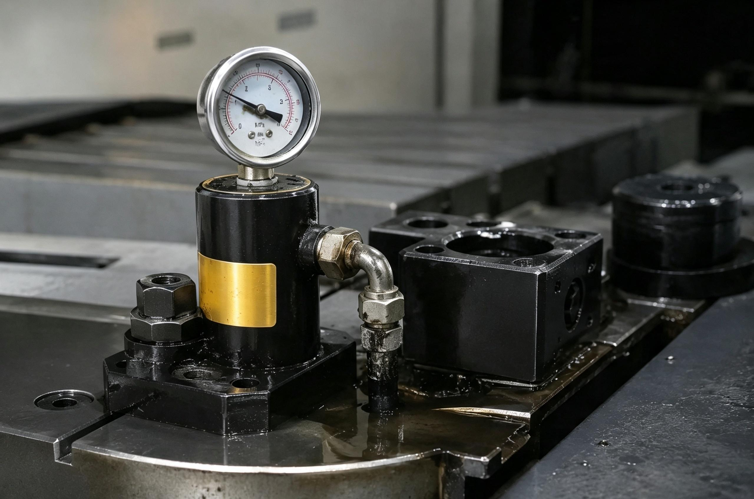
Before Opening the Hydraulic Circuit
Hydraulic pressure can remain trapped after the pump stops. Check valves, cylinders, valves, and accumulators can hold stored energy. ISO 4413 covers safety requirements for hydraulic fluid-power systems.[1]
Before service, isolate the machine, control stored hydraulic energy, and mechanically support anything that can move or fall. OSHA requires hazardous stored or residual energy to be relieved, disconnected, restrained, or otherwise made safe before servicing.[2]
Never use your hand to search for a leak. OSHA recorded a hydraulic injection injury in which oil released at 3,000 psi pierced a worker's skin and required hospitalization.[3]
Pressure Will Not Reach the Setpoint
If the target is 3,000 psi but the system stops at 2,200 psi, check components that affect pressure while the pump is running.
| What You Find | Likely Area |
|---|---|
| Pressure rises slowly and never reaches the setpoint | Pump output, suction problem, large internal leak |
| Pressure repeatedly stops at about the same low value | Relief valve, pressure-control setting |
| Oil is visibly escaping | Hose, fitting, seal, manifold, connection |
| Oil continuously returns to tank | Directional valve or pressure-control circuit |
| Problem becomes much worse when hot | Pump wear or increased internal leakage |
Also check reservoir level, suction restrictions, suction-side air leaks, motor speed, and pump rotation where applicable.
If the system reaches 3,000 psi easily and only loses pressure after the pump stops, pump displacement is normally a lower-priority suspect.
Pressure Drops After the Pump Stops
Record the pressure instead of describing it as “slow” or “fast.” Use the same hold time every time.
| Example | Start | 30 sec | 1 min | 5 min |
|---|---|---|---|---|
| Small initial settling | 3,000 psi | 2,850 psi | 2,830 psi | 2,820 psi |
| Continuing pressure decay | 3,000 psi | 2,880 psi | 2,750 psi | 2,100 psi |
The values above are diagnostic examples, not universal pass/fail limits.
A drop that happens mainly in the first few seconds and then stabilizes can come from hose expansion, trapped air, fixture flex, or workpiece seating.
A pressure drop that continues while oil temperature and clamp position remain stable points more strongly to an oil leak path.
Check:
- directional valve leakage,
- check-valve leakage,
- piston-seal bypass,
- external leakage,
- and movement of the piston or workpiece.
Oil Is Visible Around the Clamp
Clean the area first, run one controlled cycle, and identify where fresh oil appears.
| Leak Location or Timing | Check |
|---|---|
| Oil appears along the rod | Rod seal, rod scratches, corrosion, side load |
| Oil appears mainly while the rod moves | Rod surface and rod seal |
| Oil appears while the clamp is stationary under pressure | Static seals, fittings, manifold joints |
| Oil appears only near maximum pressure | Seal condition, fittings, component pressure rating |
| Oil appears around a hose end | Hose, fitting, crimp, port connection |
Do not assume that a small visible leak is harmless. A clamp circuit may contain only a small trapped oil volume, so losing a small amount can cause a noticeable pressure change.
No Oil Is Visible
No external oil does not mean there is no leak.
Check internal paths:
- oil bypassing the piston seal,
- oil leaking through a directional valve,
- oil passing a check-valve seat,
- pilot pressure holding a pilot-operated check valve partly open,
- or oil returning through another control-valve path.
Also measure movement. A pressure drop with measurable piston or workpiece movement may come from changing hydraulic volume rather than a large oil leak.
Seal Damage Shows What Caused the Failure
Do not replace a damaged seal without checking why it failed.
| What the Seal Looks Like | What to Check |
|---|---|
| Heavy wear on one side | Side loading, poor alignment |
| Long scratches | Dirty oil, damaged rod, scored bore |
| Hard or brittle material | Heat, age, incompatible fluid |
| Seal material pushed out of the groove | Excess pressure, excessive clearance, wrong seal, installation damage |
| New seal fails again quickly | Rod damage, alignment, contamination, wrong material |
The rod seal prevents oil from leaking outside along the rod. The piston seal limits oil bypass inside the cylinder. The wiper keeps chips and dirt from entering with the rod.
If oil is visible outside, the rod seal or an external connection deserves attention. If no oil is visible but pressure and position cannot be held, piston bypass is one possible cause.
Cylinder Movement Does Not Prove Piston-Seal Failure
If the clamp drifts, do not rebuild the cylinder until the rest of the circuit has been checked.
The same movement can be caused by:
- piston-seal bypass,
- directional-valve leakage,
- check-valve leakage,
- external oil loss,
- or workpiece movement that lets the piston follow the load.
The useful test is to separate the cylinder from the upstream leak paths using the equipment's approved test method. If the local clamp circuit still loses pressure, concentrate on the actuator and local holding components. If it holds, move upstream in the circuit.
Directional Valve Leaks Internally
A valve can look completely dry while oil leaks internally.
Many spool-type directional valves have operating clearance between the spool and bore. The amount of leakage depends on valve design, wear, pressure difference, oil viscosity, and temperature.
Check the valve symbol as well as the valve condition. In the neutral position, actuator ports may be blocked, connected to tank, or connected in another arrangement.
If the circuit requires very low static leakage, do not assume that any standard spool valve will provide the same holding performance as a seat or poppet-type holding valve.
Check Valve Will Not Hold Pressure
A check valve may leak because its sealing surfaces cannot close fully.
Check for:
- particles on the seat,
- poppet or seat damage,
- worn sealing surfaces,
- incorrect assembly or installation,
- and damaged internal parts.
The problem may be intermittent. A particle can hold the valve open on one cycle and move away on the next.
For a pilot-operated check valve, also check:
- residual pilot pressure,
- incorrect pilot piping,
- backpressure,
- and whether the pilot signal fully releases.
One Clamp Loses Pressure
If several clamps share one power unit, compare them before dismantling anything.
| Clamp | Start Pressure | Pressure After 5 min |
|---|---|---|
| Clamp 1 | 3,000 psi | 2,950 psi |
| Clamp 2 | 3,000 psi | 2,930 psi |
| Clamp 3 | 3,000 psi | 2,150 psi |
| Clamp 4 | 3,000 psi | 2,940 psi |
In this example, start with Clamp 3 and its local branch:
- cylinder seals,
- local hose or drilled passage,
- local fittings,
- local check valve,
- and workpiece contact under that clamp.
All Clamps Lose Pressure
If several clamps lose pressure at the same time, start with parts they share.
- main directional valve,
- common check valve,
- main manifold,
- pressure-control valve,
- accumulator,
- power-unit internal valves,
- and common supply piping.
Several cylinders developing identical seal leakage at the same time is usually less likely than one shared circuit fault.
Pressure Loss Gets Worse When Hot
Test the same hold period when the system is cold and again at normal operating temperature.
| Example Test | Start | After 5 min | Pressure Loss |
|---|---|---|---|
| Cold | 3,000 psi | 2,850 psi | 150 psi |
| Normal operating temperature | 3,000 psi | 2,300 psi | 700 psi |
The numbers above are examples. The important result is that the hot-state pressure loss is much larger.
Check:
- directional-valve internal leakage,
- check-valve sealing,
- piston-seal condition,
- pump internal wear if pressure also becomes difficult to build,
- and whether the oil viscosity matches the equipment requirement.
Do not use a fixed “psi per 10°C” rule. Pressure change in a closed circuit depends on oil volume, trapped air, hoses, component stiffness, and thermal expansion.
Pressure Is Normal but the Workpiece Moves
If the gauge stays near the target but the part moves, stop looking only at hydraulic pressure.
Check:
- chips under the workpiece,
- burrs on supports or locating faces,
- thin-wall deformation,
- fixture flex,
- loose support points,
- clamp-pad sliding,
- incorrect clamp position,
- and cylinder bottoming.
Example:
- Initial pressure: 3,000 psi
- Pressure after the part seats: 2,600 psi
- Clamp movement: 0.18 mm
- Workpiece/support movement: 0.15 mm
That pattern gives a strong reason to inspect the mechanical load path rather than replacing a valve first.
Check the complete path:
clamp → workpiece → support → fixture → machine table
Large and thin workpieces need support close to the cutting and clamping areas. See the practical workholding examples in how to hold a large metal plate during machining.
Full Pressure but No Clamp Force
A cylinder can reach full pressure after it reaches the end of its stroke. The gauge may show 3,000 psi even though the clamp is not properly loading the workpiece.
Check that:
- the clamp actually contacts the workpiece,
- contact occurs before the end of the cylinder stroke,
- the clamp arm is in the correct position,
- the workpiece support height is correct,
- and the rod is not being pushed sideways.
Recheck these points whenever the workpiece is turned or moved to a new setup. This is particularly important during six-sided machining of mold blocks, where the support and contact surfaces change between setups.
Calculate the Remaining Holding Force
For a simple hydraulic cylinder:
Force = Pressure × Effective Piston Area
This is the basic pressure-force relationship used in hydraulic systems.[4]
With a 2 in² effective piston area:
| Pressure | Theoretical Cylinder Force |
|---|---|
| 3,000 psi | 6,000 lbf |
| 2,750 psi | 5,500 lbf |
| 2,500 psi | 5,000 lbf |
| 2,250 psi | 4,500 lbf |
| 2,000 psi | 4,000 lbf |
If the job needs at least 4,500 lbf theoretical cylinder force, the pressure in this example must stay at or above:
4,500 lbf ÷ 2 in² = 2,250 psi
At 2,000 psi, the gauge still looks highly pressurized, but theoretical force is already 500 lbf below the example requirement.
For actual workholding, also account for arm geometry, friction, supports, cutting-force direction, and the clamp manufacturer's rated force. More examples are available in hydraulic clamping pressure for mold steel blocks.
Rod-Side Force Is Lower
On a normal double-acting cylinder, the rod takes up part of the piston area.
Example:
- Full piston area: 2.0 in²
- Rod area: 0.5 in²
- Rod-side effective area: 1.5 in²
At 3,000 psi:
- Full piston side: 3,000 × 2.0 = 6,000 lbf
- Rod side: 3,000 × 1.5 = 4,500 lbf
Do not use the full piston area for a rod-side force calculation.
Pump Cycling Is Getting Faster
For a pressure-switch-controlled power unit, compare restart frequency with the machine's previous normal behavior.
| Example Condition | Restart Interval | Approximate Intervals in 8 Hours |
|---|---|---|
| Earlier condition | 18 minutes | About 27 |
| Later condition | 9 minutes | About 53 |
| Large change | 2 minutes | About 240 |
The values are examples, not universal limits. A change from 18 minutes to 2 minutes matters because the same machine now needs pressure restored much more often.
Check external leakage, valve leakage, piston bypass, accumulator condition, and pressure-switch settings.
If the pump should restart at 2,700 psi but does not restart until 2,000 psi, check the pressure switch, transducer, wiring, relay, or control logic.
Air or Hose Expansion Causes Early Pressure Settling
Trapped air commonly causes jerky movement, slow pressure rise, inconsistent position, noise, and a soft or springy response.
Flexible hose expansion usually causes a limited settling effect rather than continuous pressure loss.
Example:
3,000 psi → 2,850 psi in 30 seconds → 2,820 psi after 5 minutes
If pressure becomes stable after the initial drop, check:
- trapped air,
- hose expansion,
- fixture movement,
- and workpiece seating.
If pressure continues falling after the system stops moving and temperature is stable, look for a real oil leak path.
Do not convert pressure drop directly into leakage flow. A loss of 100 psi per minute can represent very different oil volumes in two circuits with different hose lengths, trapped volumes, and air content.
Wrong or Dirty Oil Increases Leakage and Wear
Use the fluid type and viscosity specified for the equipment.
Wrong fluid can change seal behavior. ISO 6072:2011 provides methods for evaluating compatibility between hydraulic fluids and standard elastomeric materials.[5]
Particles can damage:
- rod seals,
- piston seals,
- cylinder surfaces,
- check-valve seats,
- directional valves,
- and pumps.
Oil can look clean and still contain damaging particles. ISO 12669:2017 gives a method for determining the required cleanliness level of a hydraulic system.[6] ISO 4406:2021 defines the coding method for solid-particle contamination levels.[7]
If a new seal, check valve, and another hydraulic component fail within a short period, test the oil and investigate contamination instead of treating each failure separately.
Measure at the Clamp, Not Only at the Pump
A pump gauge does not always show the pressure reaching the affected clamp.
Example:
- Pump pressure: 3,000 psi
- Reduced clamp branch: 1,500 psi
If the clamp is downstream of a reducing valve, measure downstream when diagnosing that clamp.
Use a gauge range that makes the expected pressure change easy to read. A 0–10,000 psi gauge is a poor choice for detecting small changes of a few hundred psi.
ISO 9110-2:2020 specifies procedures for measuring average steady-state pressure in hydraulic fluid-power conduits.[8]
Verify the Repair with the Same Test
Do not judge a repair by the fact that a new seal or valve was installed. Repeat the original pressure test under similar load and temperature conditions.
| Measurement | Before Repair | After Repair |
|---|---|---|
| Initial pressure | 3,000 psi | 3,000 psi |
| Pressure after 5 min | 2,250 psi | 2,920 psi |
| 5-minute pressure loss | 750 psi | 80 psi |
| Pump restart interval | 70 seconds | 14 minutes |
These are example values, not universal pass limits.
After repair, confirm all four points:
- pressure stays above the minimum required for the job,
- the clamp position stays stable,
- the workpiece does not move,
- and the result remains acceptable after the oil reaches normal operating temperature.
Stop the Machine If These Conditions Appear
- The clamp releases unexpectedly.
- The workpiece moves during cutting.
- Pressure falls below the calculated minimum needed for holding.
- A high-pressure external leak is active.
- The pressure suddenly falls much faster than before.
- The pump has to restart almost continuously to maintain pressure.
- Clamp force cannot be confirmed.
A pump can continue replacing leaked oil while the fault gets worse. If loss of pressure can let the workpiece slide, rotate, lift, or eject, stop production and correct the fault.
Finally
Use measured pressure, movement, and time to find the fault. A clamp that falls from 3,000 psi to 2,100 psi in five minutes needs a different investigation from one that falls to 2,850 psi in 30 seconds and then stays stable. Compare one clamp with the others, test cold and hot conditions, and calculate the minimum pressure from the required holding force. With a 2 in² piston area, 2,250 psi produces 4,500 lbf theoretical force; 2,000 psi produces only 4,000 lbf. After repair, repeat the same timed pressure test and confirm that both the clamp and workpiece remain in position.