

A newly installed duplex milling machine is not ready for production just because it powers on and the axes move normally. What matters is whether it can cut two opposite faces to the required size, keep them parallel, hold squareness to the chosen datum, and repeat the result once the machine is warm.
A practical check usually starts with the installation and machine level, then moves to spindle and cutter condition, head alignment, parallelism and squareness. CNC positioning is checked when the machine specification requires it. After that, make a controlled test cut and inspect the finished part at several points. If the numbers repeat and stay inside the OEM or contract limits, the machine can be accepted.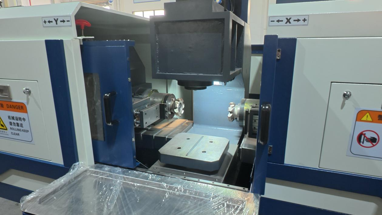
Do not apply one accuracy value to every CNC duplex milling machine. A small precision machine and a long-bed machine are not tested over the same distance or necessarily to the same limits. ISO 230-1 gives methods for geometric testing of machine tools under no-load or quasi-static conditions, while the actual pass/fail values should come from the machine manufacturer or purchase specification.[1]
Start With the Acceptance Limits
Before touching an indicator, find the acceptance sheet and write down what you are actually checking. Use the purchase specification, factory inspection report, OEM installation manual and any customer-specific quality requirements.
A number by itself is not enough. For example:
Parallelism: 0.02 mm
does not tell you much. A useful requirement looks more like:
Parallelism: 0.02 mm over 1,000 mm
The test length matters because the same angular error produces a larger linear deviation over a longer distance. The same point applies to squareness, straightness and other geometric checks.
It is also worth writing down exactly what two things are being compared. “Squareness” might mean the spindle axis relative to table travel, X travel relative to Y travel, or a finished side face relative to Datum A. Those are not the same test.
| Test | Specified Limit | Test Length | Actual Result | Pass/Fail |
|---|---|---|---|---|
| Machine level | OEM specification | Specified positions | — | — |
| Spindle runout | OEM specification | Specified test-bar position | — | — |
| Face parallelism | OEM specification | Specified length | — | — |
| Squareness | OEM specification | Specified height/length | — | — |
| CNC positioning | OEM specification | Axis travel | — | — |
| Test-cut size | Drawing or acceptance limit | Workpiece size | — | — |
Check the Installation and Level
Fine alignment is wasted effort if the machine is sitting badly on the foundation. First make sure all specified support points are carrying the machine correctly, the leveling pads are seated, shipping locks have been removed, and the anchor bolts have been installed according to the OEM procedure.
Also look for transport damage around the spindle heads, guide covers, scales, cables and lubrication or hydraulic lines. A bent bracket or damaged scale can create symptoms that look like an accuracy problem later.
On a long machine, do not take one level reading in the middle and call it finished. Measure at several positions along the bed, in both longitudinal and transverse directions.
The following numbers are only an example of what a measurement set may look like. They are not universal acceptance limits.
| Position | Longitudinal Reading | Transverse Reading |
|---|---|---|
| Left | +0.01 mm/m | +0.02 mm/m |
| Left-center | +0.01 mm/m | +0.01 mm/m |
| Center | +0.01 mm/m | +0.01 mm/m |
| Right-center | +0.02 mm/m | +0.02 mm/m |
| Right | +0.02 mm/m | +0.04 mm/m |
Here, the right-side transverse reading has moved away from the rest. That does not automatically mean the machine fails. It tells you where to look first: support loading, leveling-pad seating, anchor stress or possible bed twist.
Overall level and bed twist are related but not identical. Both still need to meet the manufacturer's installation limits. Twist is particularly important because it can change the relationship between the two heads and the workpiece as the carriage travels.
If the OEM procedure calls for it, move the heavy table, carriage or head assembly through the specified positions and repeat the level readings. A large change when the moving mass shifts from one end to the other deserves investigation before any head alignment work begins.
Recheck After Anchoring
Once the anchor bolts are tightened, take the level readings again. Anchors are there to hold the machine, not pull it into a new shape.
| Position | Before Tightening | After Tightening |
|---|---|---|
| Left | 0.00 mm/m | +0.01 mm/m |
| Center | +0.01 mm/m | +0.01 mm/m |
| Right | +0.01 mm/m | +0.04 mm/m |
If the right side moves from +0.01 to +0.04 mm/m after tightening while the other positions barely change, do not start correcting the spindle heads. Fix the support or anchoring issue first.
Set the Datum Before Measuring
Every geometric measurement needs a clear reference. Otherwise, two technicians can take perfectly good measurements and still end up comparing different things.
Record the main datum surface, the machine directions, which head is called left and right, and where the test starts. For one machine the setup might be:
- Datum A: the specified fixture or machine reference surface;
- X: workpiece length direction;
- Y: vertical direction;
- Z: the direction between the two opposed milling heads.
The actual axis names depend on the machine. Use the machine drawing or manual rather than assuming every duplex mill follows the same convention.
Mark the workpiece too. Simple X+, X−, Left Head and Right Head marks become very useful later when you are trying to work out whether a taper follows the machine or follows the part.
Then clean the references. Table surfaces, fixture faces, spindle tapers, test bars, precision squares and indicator contact areas all need to be clean. A chip or burr only a few hundredths of a millimeter thick can be larger than the error you are trying to measure.
Check the Spindles
Check the two spindle systems separately before deciding whether the heads are aligned with each other.
Clean the spindle taper, fit a suitable test bar and place the indicator close to the spindle nose. Rotate the spindle by hand only when the OEM procedure allows it. Then repeat the test farther along the bar.
| Test-Bar Check | 50 mm From Spindle Nose | 300 mm From Spindle Nose |
|---|---|---|
| First installation | 0.004 mm | 0.018 mm |
| Bar removed, cleaned and reinstalled | 0.005 mm | 0.017 mm |
Those two sets are close enough to show that the setup is reasonably repeatable. The larger reading at 300 mm is worth investigating, but it does not by itself prove the spindle head is out of square with the machine axis.
It may come from the test bar, taper seating or the spindle/test-bar relationship. That distinction matters.
Now look at a less stable example:
| Test-Bar Check | 50 mm From Spindle Nose | 300 mm From Spindle Nose |
|---|---|---|
| First installation | 0.004 mm | 0.018 mm |
| After reinstalling | 0.012 mm | 0.031 mm |
Here the result changes too much after a simple reinstall. Before adjusting the machine, check taper cleanliness, bar seating and the indicator setup.
One useful habit is to return the indicator to the first measuring point after every sweep. If zero does not come back, something in the setup may have moved.
Do Not Forget the Cutter
A good spindle reading does not guarantee a good finished face. The cutter body, arbor, insert pockets and inserts all sit between the spindle and the workpiece.
One chip under an insert is enough to lift that insert above the rest. It may then remove most of the finishing stock and leave repeating marks or a local high/low pattern that looks like a machine problem.
| Insert Position | Example Indicator Reading |
|---|---|
| Insert 1 | 0.000 mm |
| Insert 2 | +0.003 mm |
| Insert 3 | +0.004 mm |
| Insert 4 | +0.012 mm |
| Insert 5 | +0.003 mm |
Insert 4 clearly stands out in this example. Check the pocket, seating face and insert before touching machine alignment.
The 0.012 mm value is not being presented as a universal cutter limit. Different face mills use different setting methods and allowable runout, so follow the cutter manufacturer's procedure.
Compare the Two Heads
Two head problems often look similar at first, but the finished part tells a different story.
If the distance between the heads is wrong by a nearly constant amount, the part may simply come out uniformly too thick or too thin. If one head is tilted, the error tends to grow along the length or height.
Compare these two patterns.
Nearly constant difference:
| Position | Left Head | Right Head | Difference |
|---|---|---|---|
| A | 0.000 mm | +0.005 mm | 0.005 mm |
| B | +0.003 mm | +0.008 mm | 0.005 mm |
| C | +0.005 mm | +0.010 mm | 0.005 mm |
| D | +0.006 mm | +0.011 mm | 0.005 mm |
Difference growing with travel:
| Position | Left Head | Right Head | Difference |
|---|---|---|---|
| A | 0.000 mm | 0.000 mm | 0.000 mm |
| B | +0.002 mm | +0.006 mm | 0.004 mm |
| C | +0.004 mm | +0.013 mm | 0.009 mm |
| D | +0.006 mm | +0.020 mm | 0.014 mm |
The second case is the one that should send you back toward straightness, angular alignment, guideway relationship or bed twist. The difference is not fixed; it gets worse as the machine travels.
Separate Flatness From Parallelism
This is an easy place to make a wrong conclusion.
If you measure the thickness of a block at several points and see 0.012 mm variation, that does not automatically mean the two faces have 0.012 mm parallelism error. One or both surfaces may also be bowed, hollow or locally high.
For example:
- Face A local form variation: 0.008 mm;
- Face B local form variation: 0.006 mm;
- measured thickness variation: 0.012 mm.
The 0.012 mm thickness change contains more than one possible error source. For tight acceptance work, check surface form with a method suited to the part and tolerance, such as an indicator-based setup, CMM or the OEM-specified method.
Measure Parallelism Over a Known Length
For the machine check, use the OEM test arrangement and say exactly what is being compared. “X-axis travel relative to Datum A” is useful. “Parallelism check” by itself is vague.
An example over 1,000 mm might look like this:
| Position | Reading |
|---|---|
| 0 mm | 0.000 mm |
| 200 mm | +0.003 mm |
| 400 mm | +0.006 mm |
| 600 mm | +0.008 mm |
| 800 mm | +0.007 mm |
| 1,000 mm | +0.006 mm |
The indicated variation is:
0.008 − 0.000 = 0.008 mm
Write the result as 0.008 mm over 1,000 mm. Leaving out the 1,000 mm removes an important part of the information.
Where the test method calls for it, run the same check in the opposite direction.
| Machine Position | Forward Travel | Reverse Travel |
|---|---|---|
| 0 mm | 0.000 mm | +0.001 mm |
| 500 mm | +0.006 mm | +0.005 mm |
| 1,000 mm | +0.008 mm | +0.008 mm |
Those readings are close. If the return value at the original zero suddenly comes back at +0.008 mm instead, check for play, reversal effects or movement in the measuring setup before calling it a machine geometry error.
Measure the Finished Part at Several Points
One micrometer reading at one corner tells you almost nothing about the whole face.
Here is a simple five-point example: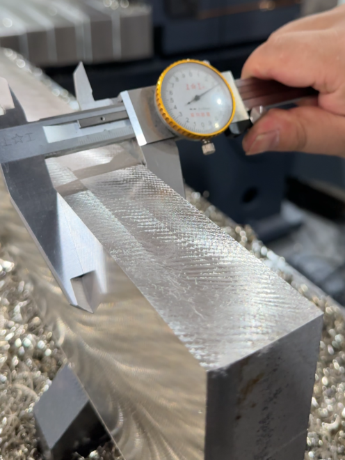
| Position | Thickness |
|---|---|
| Left upper | 200.004 mm |
| Left lower | 200.006 mm |
| Center | 200.008 mm |
| Right upper | 200.013 mm |
| Right lower | 200.014 mm |
Maximum thickness is 200.014 mm and minimum thickness is 200.004 mm, so the total thickness variation is 0.010 mm.
But the more useful clue is the direction: the numbers climb steadily from left to right. That is quite different from random high and low readings scattered around the part.
Release the Clamps Before Final Inspection
For most final part checks, the workpiece should be measured after machining clamps are released and the part is placed in the defined inspection condition, unless the acceptance procedure says otherwise.
This matters a lot with long plate, thin stock, welded parts and material carrying residual stress. A fixture can force a part flat during cutting. Once released, the part springs back.
| Position | While Clamped | After Release | Change |
|---|---|---|---|
| Left | 100.004 mm | 100.003 mm | -0.001 mm |
| Center | 100.006 mm | 100.018 mm | +0.012 mm |
| Right | 100.005 mm | 100.006 mm | +0.001 mm |
The middle changes far more than the ends after unclamping. That points you toward clamping force, support position, workpiece stiffness or residual material stress before machine alignment.
Check Squareness the Same Way: With a Clear Datum
Squareness only means something when both directions are defined.
Suppose the indicator changes by 0.012 mm over 500 mm. The result is:
0.012 mm over 500 mm
Expressed per meter:
0.012 ÷ 500 × 1,000 = 0.024 mm/m
Now compare that with 0.006 mm over 250 mm:
0.006 ÷ 250 × 1,000 = 0.024 mm/m
The raw deviations look different, but the angular rate is the same. This is why measurement length should always travel with the result.
Keep the square and datum surface clean. The indicator contact direction matters too. If the indicator sits at a large angle to the measured movement, cosine error can make the displayed movement smaller than the actual movement.
For the finished workpiece, establish a suitable datum face first. Then check the adjacent surface with the measuring equipment required for the tolerance. A normal workshop square and a visible light gap are not enough for tight acceptance work.
Check CNC Positioning When It Matters
Not every installation article needs to turn into a full laser calibration procedure. But if final size depends strongly on commanded axis position, or the acceptance specification calls for it, positioning and repeatability should be checked.
ISO 230-2 specifies methods for testing the positioning accuracy and repeatability of numerically controlled machine-tool axes using repeated measurements at defined target positions.[2]
Take this example. The target is 500.000 mm:
- 500.015 mm;
- 500.014 mm;
- 500.015 mm;
- 500.016 mm;
- 500.015 mm.
The axis is consistently around +0.015 mm away from target, but it repeats that position closely.
Now compare:
- 500.002 mm;
- 500.018 mm;
- 499.994 mm;
- 500.011 mm;
- 500.020 mm.
The second set is much less stable. A repeatable position error may be suitable for calibration or OEM-approved compensation. A result that jumps around needs diagnosis first.
Do the Final Checks at a Stable Temperature
A cold machine and a machine that has been cutting for two hours may not give the same numbers. Spindles, ball screws, bearings, motors and coolant all add heat.
ISO 230-3 deals with thermal effects from the environment, rotating spindles, linear-axis movement and other machine motion.[3]
Do not invent a universal warm-up time. Twenty minutes may be enough for one machine and nowhere near enough for another. Follow the OEM procedure, or watch whether the machine has actually stabilized.
| Check | Example Reading |
|---|---|
| Start | 0.000 mm |
| Warm-up check 1 | +0.012 mm |
| Warm-up check 2 | +0.018 mm |
| Warm-up check 3 | +0.020 mm |
| Warm-up check 4 | +0.020 mm |
The useful part of this example is not whether +0.020 mm is good or bad. It is the trend: the reading moves, then settles.
The same thing can show up in parts:
| Test Part | Measured Thickness |
|---|---|
| Part 1 | 100.018 mm |
| Part 2 | 100.011 mm |
| Part 3 | 100.007 mm |
| Part 4 | 100.005 mm |
| Part 5 | 100.005 mm |
Parts 4 and 5 are much closer to each other than the early parts. If you see this kind of trend, deal with thermal behavior before changing mechanical alignment.
Choose a Test Piece That Can Actually Show an Error
A tiny coupon on a long-bed duplex mill is an easy test, but not a very useful one.
The test piece should be rigid enough to measure accurately and large enough to use a meaningful part of the normal machining range. There is no single size that fits every machine.
For example, the TH-350NCG has a stated cutting-size range of 20–350 mm, while the TH-5015NC is built for much longer stock, with two-side machining up to 1,500 mm in its stated range. A short block that looks perfect may still tell you very little about geometry over a long travel.
Larger machines such as the TH-1885NC again work over a different range, so the OEM acceptance piece and test length should match the actual model.
Stable material is preferable. Thin flame-cut plate or stressed material can move during roughing and make a good machine look bad.
Control the Test Cut
Write down the conditions before cutting: material, starting size, cutter diameter, insert type, spindle speed, feed, depth of cut, finishing allowance, coolant, clamping method and workpiece orientation.
That may seem like a lot of detail, but it prevents a common problem: repeating the test later under completely different cutting conditions and then wondering why the result changed.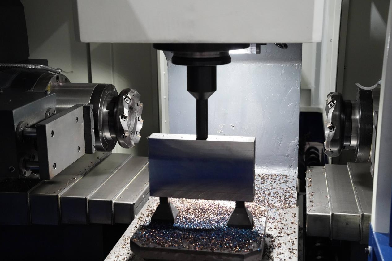
A duplex milling machine is built to machine two opposite faces in one setup. Machines used for four-side work can then rotate or reposition the part and machine the remaining sides; this four-side duplex milling process shows the basic sequence.
For installation acceptance, use conditions that resemble real production. Do not create a very light, very small cut that hides problems the machine will see every day.
Watch What Happens When Both Heads Cut
This is one of the checks that matters specifically on a duplex machine.
Each head may look fine on its own. The problem appears only when both engage the part together.
Before the test, compare cutter condition, stock allowance, depth of cut, insert seating and workpiece support on both sides. If the control shows spindle load, a large imbalance is worth investigating too.
For example, if one spindle stays near 42% load and the other near 68% during what should be a similar cut, check whether one side has more stock, different cutter engagement or worn inserts.
Those percentages are only illustrative. Normal spindle load depends on the machine, material and cutting conditions.
If each head cuts well separately but the part changes shape or size only during simultaneous cutting, look at combined cutting force, workpiece support, fixture stiffness and structural deflection before changing static alignment.
Use Roughing and Finishing to Separate Load Error From Geometry
Roughing and finishing tell you different things.
A roughing pass removes more stock and creates more cutting force. It may also release material stress. A light finishing pass puts less load into the part and fixture.
| Cutting Condition | Thickness Variation Over 800 mm |
|---|---|
| Heavier cutting pass | 0.026 mm |
| Light finishing pass | 0.009 mm |
Here the variation drops from 0.026 to 0.009 mm when the load is reduced. That is a strong clue that cutting-force deflection, support, fixture rigidity or workpiece stiffness is involved.
It still does not tell you whether 0.009 mm passes the machine specification. That decision remains tied to the OEM or contract limit.
If almost the same taper remains under both heavy and light cuts, basic machine geometry moves higher on the suspect list.
Make the Final Test Cut
A sensible final sequence is straightforward:
- clean the fixture and workpiece;
- clamp the test piece in the defined position;
- rough both opposite faces if required;
- leave the specified finishing allowance;
- allow the machine and part to reach the required condition;
- finish both faces with controlled parameters;
- stop the machine safely;
- remove burrs without damaging the reference surfaces;
- release the clamps;
- move the part to the defined inspection setup;
- measure the finished geometry.
ISO 230-12 deals with the accuracy of finished test pieces and recognizes that final workpiece error can include geometric, synchronization and dynamic effects.[4]
Use a Grid, Not One Number
For a rectangular block, a 3 × 3 measurement grid is often far more useful than one reading at each end.
| Point | Thickness |
|---|---|
| L1 | 100.002 mm |
| L2 | 100.003 mm |
| L3 | 100.002 mm |
| C1 | 100.006 mm |
| C2 | 100.007 mm |
| C3 | 100.006 mm |
| R1 | 100.011 mm |
| R2 | 100.012 mm |
| R3 | 100.011 mm |
The numbers climb steadily from left to right. If the report only says “maximum variation = 0.010 mm,” you lose the part that is most useful for troubleshooting: where the error is going.
Use the Error Pattern to Find the Cause
| What You See | Where to Look First |
|---|---|
| Both faces stay parallel, but the whole part is too thick or too thin | Programmed size, tool offset, head position, cutter size |
| Thickness steadily increases from one end to the other | Bed twist, head alignment, axis straightness, guide relationship |
| Thickness changes from top to bottom | Head squareness, datum, fixture alignment, workpiece seating |
| One face is good and the other is poor | Affected spindle, cutter runout, insert seating, head alignment |
| The center differs from both ends | Workpiece bending, support position, straightness, surface form |
| The readings look random | Measurement repeatability, chips, cutter condition, fixture movement, vibration |
| Taper becomes much worse during a heavy cut | Cutting-force deflection, fixture stiffness, workpiece stiffness, head stiffness |
| The part changes mostly after the clamps are released | Clamping force, support position, residual material stress |
| Dimensions drift while the machine warms | Spindle heat, axis heat, coolant temperature, room temperature |
| Regular repeating cutter marks appear | Insert height, damaged insert, cutter runout, cutter seating, spindle condition |
The key is not to change everything at once. If the tool, fixture, offsets and head alignment all change during the same troubleshooting session, you may eventually get a good part but never know what fixed it.
Make Sure the Measurement Is Repeatable
A precision adjustment made from bad measurement data usually creates another problem.
This is a stable set:
- 100.006 mm;
- 100.006 mm;
- 100.007 mm;
- 100.006 mm.
The spread is only 0.001 mm.
This set is very different:
- 100.002 mm;
- 100.013 mm;
- 99.998 mm;
- 100.010 mm.
The spread is 0.015 mm. If you are trying to judge a machine tolerance around that size, the measurement itself is not stable enough to support a confident adjustment.
Check instrument zero, mounting, contact direction, surface cleanliness, measuring force, part temperature and calibration status. The measuring tool also needs enough resolution for the tolerance being checked.
Repeat the Relevant Checks After Adjustment
Do not assume one correction leaves everything else untouched.
After leveling changes, recheck the machine level, head relationship, squareness and the relevant cutting test. After head alignment, recheck the test bar, parallelism and finished part. After CNC calibration or compensation, repeat the position checks and final dimension.
For tight production work, make more than one test piece too.
| Test Piece | Minimum Thickness | Maximum Thickness | Variation |
|---|---|---|---|
| Part 1 | 100.002 mm | 100.010 mm | 0.008 mm |
| Part 2 | 100.003 mm | 100.011 mm | 0.008 mm |
| Part 3 | 100.002 mm | 100.010 mm | 0.008 mm |
That is a stable pattern. If the three variations are 0.008, 0.009 and 0.027 mm instead, do not hide the 0.027 mm part inside an average. Find out why it is different.
Know When to Stop Adjusting
There are times when continuing to turn adjustment screws only makes the situation harder to understand.
Stop and investigate if the machine level changes greatly whenever the carriage moves, the indicator cannot return to zero, the same clean test bar gives very different results after reinstalling, or repeated measurements vary as much as the tolerance you are trying to verify.
The same applies if geometry keeps drifting as the machine warms, anchor tightening repeatedly changes the bed shape, or one correction makes another major relationship much worse.
Call the OEM or a qualified service technician if spindle runout remains outside the specified limit, the bed cannot be leveled within its adjustment range, transport damage is found, or the required correction involves structural disassembly or work outside the service procedure.
Keep the Work Safe
Accuracy checks often put a technician close to spindles, cutters and moving axes. OSHA identifies milling machines among equipment that normally requires point-of-operation guarding, and fixed machinery must be securely anchored to prevent movement.[5]
Servicing can also expose workers to electrical, mechanical, hydraulic or other stored energy. OSHA requires suitable energy-control procedures where unexpected startup or stored-energy release can cause injury.[6]
Do not bypass an interlock or reach near an energized cutter just to get one more measurement. Follow the OEM service procedure and the site's safety rules.
Save the Final Baseline
Keep the commissioning results. They become very useful later when a machine that once cut well starts producing taper or size drift.
Record the machine model and serial number, installation date, level readings, spindle results, parallelism and squareness with their test lengths, positioning results if checked, test-piece measurements, cutting parameters, thermal condition and any adjustment or CNC compensation that was made.
“Parallelism = 0.008 mm” is weak maintenance data.
“Parallelism = 0.008 mm over 1,000 mm, measured from X0 to X1000 after warm-up” can actually be repeated later.
Acceptance Checklist
- Acceptance limits and measurement lengths are defined.
- The datum and machine directions are clear.
- Foundation, supports and anchors are correct.
- Machine level meets the OEM requirement.
- Level has been rechecked after anchoring where required.
- Both spindle systems have been checked.
- Cutters and inserts are in known good condition.
- The relationship between the two heads has been checked.
- Flatness is considered when thickness variation is used.
- Parallelism is reported together with test length.
- Squareness is reported against a defined datum and test length.
- CNC positioning is checked when required.
- Final checks are made at a defined thermal condition.
- A representative test piece has been machined with both heads.
- The finished part has been measured at several points.
- The part has been checked after unclamping where required.
- Critical readings are repeatable.
- No unexplained error pattern remains.
- The final results meet the OEM or contract limits.
How Large Should the Test Piece Be?
There is no universal size. Follow the OEM specification where one exists. Otherwise, choose a rigid piece large enough to expose gradual error over a meaningful part of the normal working range. A 100 mm block may look perfect even when a problem becomes obvious over 1,000 mm.
Is Thickness Variation the Same as Parallelism?
No. Thickness variation tells you how the distance between two faces changes at the measured points. If either surface is bowed, hollow or locally high, part of that change comes from surface form rather than the angle between the two faces.
Can the Machine Be Checked Without a Laser?
Many installation checks can be done with precision levels, indicators, test bars, squares and finished-part measurements. A laser interferometer or other higher-level system becomes important when the acceptance specification requires formal positioning, straightness or other measurements that simpler equipment cannot verify reliably.
What If Geometry Passes but the Test Cut Still Fails?
Look at what a static indicator test does not reproduce: cutter runout, cutting force, insert seating, fixture stiffness, workpiece stress, thermal growth and the combined load from both milling heads. If a heavy pass shows 0.026 mm variation but a light finishing pass reduces it to 0.009 mm over the same 800 mm, load-related deflection deserves attention before static alignment is changed.
Conclusion
A good installation check leaves you with repeatable numbers, not just one good test part. Record parallelism with its length—for example, 0.008 mm over 1,000 mm—and do the same for squareness. Return the indicator to its starting point, compare forward and reverse movement when required, and measure the finished part at several locations after unclamping. If heavy cutting gives 0.026 mm variation but a light finish cut drops it to 0.009 mm, investigate load and support before touching alignment. When the measurement itself will not repeat within the required tolerance, fix that first.