

Large mold steel blocks are best stored flat on clean, dry, level supports, with the floor or rack checked for the real load. Support spacing should be based on the block’s thickness, span, overhang and final accuracy—not a fixed rule such as “one support every meter.” A solid 2.5 × 1.2 × 0.3 m block already weighs about 7.1 metric tons, so small mistakes in support height, contact area, lifting or moisture control can quickly become expensive.
It also helps to separate four problems that are often mixed together. A block can sag slightly under its own weight and spring back later. It can be permanently bent by overload or poor support. It can rust because of moisture. And it can move after machining because internal stresses are released. These are different problems, and they should not be solved in the same way.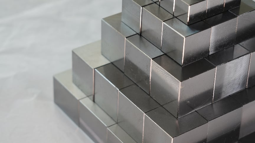
Know the Block Weight
Before choosing a rack, timber size, forklift or crane, work out how much the block actually weighs.
For a solid steel block:
Mass ≈ Length × Width × Thickness × 7,850 kg/m³
Take a block measuring 2.5 × 1.2 × 0.3 m. Its volume is:
2.5 × 1.2 × 0.3 = 0.9 m³
Approximate mass:
0.9 × 7,850 = 7,065 kg
So the block weighs about 7.1 metric tons.
| Solid Steel Block Size | Approx. Mass |
|---|---|
| 2,000 × 1,000 × 100 mm | 1.57 t |
| 2,500 × 1,200 × 200 mm | 4.71 t |
| 2,500 × 1,200 × 300 mm | 7.07 t |
| 3,000 × 1,500 × 400 mm | 14.13 t |
The numbers rise quickly. A block that does not look dramatically larger on the shop floor can be several tons heavier.
If the steel already has large pockets, holes or rough-machined cavities, do not calculate from the outside dimensions alone. Use the CAD volume, drawing, supplier value or a verified weighing method instead.
Keep the grade, heat number, dimensions, hardness if specified, and supply condition with the block. Different mold steel grades may arrive annealed, prehardened or in another condition, and that affects what happens later in machining and heat treatment.
Check the Floor and Rack
A 7-ton block does not spread its weight evenly over its full bottom face if it is sitting on two timber bars. Most of the load goes into the floor through those two contact areas.
block → support → floor
That means concentrated load matters just as much as total weight. Check the slab or floor capacity, the area directly below each support, nearby heavy equipment, rack feet, cracks, settlement, drains and floor openings.
OSHA requires walking-working surfaces to support the maximum intended load.[1]
The same idea applies to racks. A rack rated for a 10-ton evenly distributed pallet load is not automatically suitable for a 10-ton steel block sitting on two narrow bars. Beam capacity, frame capacity, anchor condition and the actual loading pattern all matter.
Keep the Block Off the Floor
Direct storage on concrete is usually a poor choice for unfinished mold steel. Suitable dunnage or a purpose-built support system gives lifting clearance, lets you inspect the underside, keeps the steel away from floor moisture and creates a more controlled support surface.
There is no benefit in raising the block higher than necessary. More height means a higher center of gravity, which can make handling less stable.
Choose the Support Material
Timber is common because it spreads the load over a reasonably wide area and has a little give. The downside is that it absorbs water, compresses, splits and changes shape with use.
Do not reuse a piece just because it still looks like a beam. Reject timber with deep cracks, crushed areas, rot, heavy warping, water saturation, chemical contamination or obvious height differences.
Steel supports are more repeatable, but they bring different problems. Oily steel-on-steel contact can slide, and a narrow steel support may mark a finished face. Ground or finished surfaces may need a suitable separator.
If your shop stores similar blocks every week, fixed engineered supports are usually easier to manage than random pieces of timber because height, spacing and lifting clearance can be standardized.
Keep the Supports Level
Spacing gets a lot of attention, but height errors can cause just as much trouble.
Imagine three supports under one block. If the middle one sits 2 mm higher than the other two, the real load sharing may be nothing like the operator expects.
Before placing the steel, clean away chips, check for crushed dunnage and compare the support heights. For critical storage, a straightedge or laser elevation check is much better than assuming nominally equal timber is still equal.
Do not level a multi-ton block with folded cardboard, random sheet-metal pieces or loose wood scraps. Those materials can move or crush under load.
Check for Twist
A block may look well supported along its length and still sit twisted.
Four pieces of 100 mm timber, for example, may no longer be the same height after repeated loading and moisture exposure. If one corner is high, the load may end up sitting on only part of the support system.
Watch for visible gaps and uneven contact during placement. Correct the support plane instead of assuming the steel will settle into position later. And do not push or rock a multi-ton block by hand to “check” it.
Set Support Spacing
There is no universal support spacing for large mold steel.
The main things to look at are block length, vertical thickness, unsupported span, end overhang, block shape, any load stacked above it and the accuracy required later.
For a simple beam, bending under its own weight rises roughly with the fourth power of the support span. That sounds abstract, but the numbers make it clear.
The example below uses a solid steel section 1,000 mm wide and 100 mm thick, supported at two points with no significant end overhang. Steel density is taken as 7,850 kg/m³ and Young's modulus as 205 GPa.
| Support Span | Calculated Self-Weight Deflection |
|---|---|
| 1.00 m | 0.006 mm |
| 1.25 m | 0.014 mm |
| 1.50 m | 0.030 mm |
| 1.75 m | 0.055 mm |
| 2.00 m | 0.094 mm |
Doubling the span from 1.0 m to 2.0 m takes the calculated bending from about 0.006 mm to 0.094 mm—roughly 16 times as much.
So moving supports “just a little farther apart” can make a much bigger difference than it looks.
Thickness Changes Stiffness
Thickness has an even stronger effect than many people expect.
In the next example, the width stays at 1,000 mm and the support span stays at 1,500 mm. Only the vertical thickness changes.
| Vertical Thickness | Calculated Self-Weight Deflection |
|---|---|
| 100 mm | 0.030 mm |
| 150 mm | 0.013 mm |
| 200 mm | 0.007 mm |
| 300 mm | 0.003 mm |
In this simple model, the 300 mm section bends only about one-ninth as much as the 100 mm section.
That is why using one support-spacing rule for both thick blocks and thin plates makes little sense.
Use the Deflection Formula Carefully
For a first check, a solid rectangular block on two simple supports can be treated as a beam under evenly distributed self-weight:
δ = 5wL⁴ / 384EI
where:
- δ = calculated elastic deflection;
- w = load per unit length;
- L = support span;
- E = Young's modulus;
- I = section stiffness.
For a rectangular section:
I = bh³ / 12
Here, b is the width and h is the vertical thickness. If the block is 2,500 × 1,200 × 300 mm and stored flat, use 1,200 mm for b and 300 mm for h.
Do not swap them. Thickness is cubed in the equation, so the wrong orientation can completely change the result.
For a solid rectangular steel section:
w = ρ × b × h × g
using approximately:
- ρ = 7,850 kg/m³;
- g = 9.81 m/s².
Keep the units consistent throughout the calculation.
Know What the Calculation Cannot Tell You
The beam formula is useful, but it is only a first check. It assumes a solid rectangular section, two simple supports, uniform self-weight, no large cavities, no important end overhang and no stacked load.
Real mold blocks are often less tidy. They may have deep pockets, steps, multiple supports or an asymmetric shape. With three or more supports, load sharing depends on support height, compression, location and block stiffness. You cannot simply divide the total load by the number of supports and assume the answer is correct.
Also keep the calculated numbers in perspective. If the theoretical deflection is 0.003 mm but one timber is 0.2 mm higher than another, the support error is already much larger than the beam calculation.
Watch the Overhang
The span between supports is only half of the picture. The steel beyond the outer supports matters too.
Moving the supports inward shortens the middle span but increases the end overhang. Moving them outward does the opposite.
If the ends extend far beyond the supports, those overhanging sections create their own bending. At that point, the simple two-support formula is no longer enough by itself.
For a regular rectangular block, roughly symmetrical support positions are usually easier to control unless the shape of the part requires something different.
Check Bearing Pressure
A narrow support pushes the same force through a smaller area, so contact pressure goes up.
Using the 7,065 kg example block:
Total weight force ≈ 7,065 × 9.81 = 69.3 kN
With two symmetrical simple supports:
Reaction at each support ≈ 34.65 kN
If each support runs across the full 1,200 mm width:
| Support Contact Width | Contact Area | Average Bearing Pressure |
|---|---|---|
| 30 mm | 36,000 mm² | 0.96 MPa |
| 60 mm | 72,000 mm² | 0.48 MPa |
| 100 mm | 120,000 mm² | 0.29 MPa |
The 30 mm support produces more than three times the average pressure of the 100 mm support.
That still does not prove whether a certain timber is safe. Its allowable load depends on the wood species, grain direction, moisture, condition and how long the load remains in place.
Stack Blocks Carefully
If blocks have to be stacked, keep the supports vertically aligned as much as practical:
upper block → support → lower block → support → floor
If the upper support sits over the middle of a large unsupported area below, the lower block has to carry extra bending load.
OSHA requires stored material to remain stable and secure against sliding or collapse.[2]
Also consider total stack weight, support crushing, center of gravity and whether one block can be removed without disturbing the others. For very heavy or precision blocks, individual storage is often easier to control.
Store Flat When Possible
Horizontal storage usually gives a large rectangular block a lower center of gravity and a more predictable support condition.
Do not stand a multi-ton block upright simply because it bends less in that direction. Vertical storage creates a tipping problem instead.
If a block must be stored vertically, use a system designed to restrain it against overturning and uncontrolled movement.
Check Forklift Capacity
Forklift capacity is not just about weight. The load center matters.
OSHA explains that capacity drops when the load's center of gravity moves farther forward than the rated load center.[3]
For a forklift rated at 10,000 kg at a 600 mm load center, a simple load-moment check gives:
| Actual Load Center | Approx. Screening Capacity |
|---|---|
| 600 mm | 10,000 kg |
| 750 mm | 8,000 kg |
| 900 mm | 6,667 kg |
| 1,000 mm | 6,000 kg |
| 1,200 mm | 5,000 kg |
At a 900 mm load center, the simple estimate drops to about 6,667 kg. The 7,065 kg block used earlier would already be above that value.
This is only a screening calculation. The forklift data plate and manufacturer information take priority because mast type, attachments, lift height, side shift and load shape can all change capacity.
Prevent Rust and Condensation
Bare P20-type, H13-type and many other tool steels can rust without ever seeing rain. Condensation, wet timber, floor washing, humid outside air, fingerprints and trapped water are enough.
The underside and the areas touching dunnage deserve special attention. They are harder to see and usually get less airflow.
Use Dew Point, Not Humidity Alone
Relative humidity by itself does not tell you whether water will form on the steel. Surface temperature matters.
| Condition | Value |
|---|---|
| Air temperature | 25°C |
| Relative humidity | 70% |
| Approx. dew point | 19°C |
| Cold steel surface | 12°C |
At 12°C, the steel is well below the roughly 19°C dew point, so condensation can form even though the building itself looks dry.
ISO 8502-4 uses air temperature, relative humidity, dew point and steel surface temperature to assess condensation risk.[4]
Do not seal a cold block while its surface remains at or below the surrounding dew point.
One important distinction: being above the dew point only tells you that condensation is less likely. It does not mean the block is thermally ready for precision machining.
Dry Hidden Areas
Water often stays where you cannot see it immediately: lifting holes, threads, drilled holes, grooves, stamped areas, packaging folds and the contact zones above dunnage.
A simple sequence works well:
- Clean the steel.
- Remove visible water.
- Dry holes and recesses.
- Give trapped moisture time to escape.
- Apply the chosen corrosion protection.
If compressed air is used, make sure the air itself is not carrying water or oil back onto the block.
Choose Rust Protection by Risk
Storage time is only one part of the corrosion risk.
| Factor | Lower Risk | Higher Risk |
|---|---|---|
| Surface | Rough stock | Ground or polished face |
| Remaining allowance | Several millimeters | Very small finishing allowance |
| Environment | Dry indoor storage | Humid, coastal, outdoor, or cycling temperature |
| Duration | Short staging | Months or unknown duration |
A rough block with 5 mm still to remove can tolerate surface damage that may be unacceptable on a ground face with only 0.2 mm left.
Choose a rust-preventive oil, removable coating, VCI system or barrier package that suits the surface and can be removed cleanly before the next operation.
Use VCI Properly
VCI stands for volatile corrosion inhibitor. It works as part of a closed or controlled packaging system; it is not a substitute for drying wet steel.
Formal specifications exist for VCI materials. U.S. Department of Defense MIL-PRF-22019 covers sealable transparent VCI barrier material.[5] MIL-PRF-3420 covers VCI-treated wrapping materials.[6]
Before wrapping, clean and dry the block, protect sharp corners that might puncture the film, and close the package as required by the selected system. Check it again after the block has been lifted or moved.
Compare Rust with Machining Allowance
The size of a rust stain matters less than the depth of the damage.
| Remaining Stock | Example Pit Depth | What It Means Geometrically |
|---|---|---|
| 5.0 mm | 0.3 mm | Large stock margin remains |
| 2.0 mm | 0.3 mm | Pit may be removed during machining |
| 0.5 mm | 0.3 mm | Only 0.2 mm theoretical margin remains |
| 0.2 mm | 0.3 mm | Pit is deeper than the remaining stock |
This is only a depth comparison, not an acceptance standard. A 0.3 mm pit on rough stock may disappear completely, while the same pit on a polished cavity or sealing face may make the surface unusable.
For common prehardened grades such as P20 / 1.2311 mold steel or 1.2738 / P20+Ni, use the actual material certificate and supplied hardness rather than relying on the grade name alone.
Inspect During Storage
A polished block stored for six weeks in a humid area deserves more attention than a rough block with several millimeters of stock in a dry room.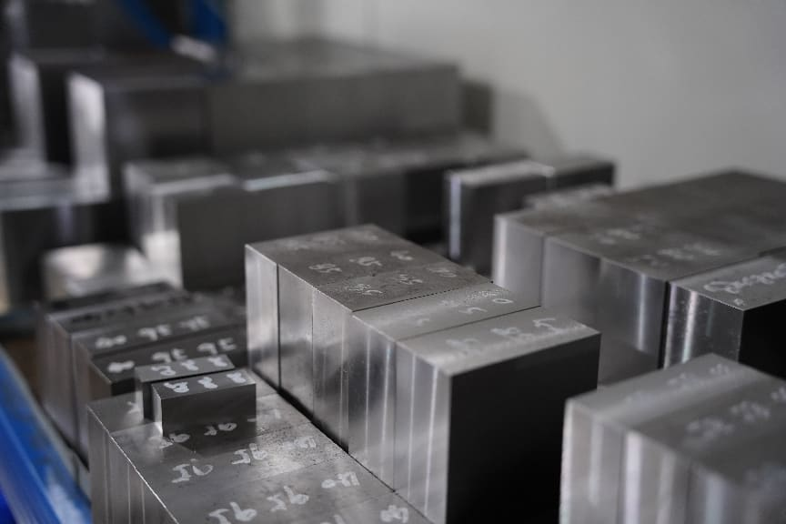
Increase inspection frequency when you have ground or polished surfaces, very little machining allowance, long storage, coastal air, outdoor exposure or large temperature swings.
Look for rust, pitting, condensation, wet or crushed dunnage, moved supports, damaged packaging, rack damage and lost identification.
And do not wait for the calendar after something unusual happens. A roof leak, flood, HVAC failure, forklift hit, torn package, relocation or long-distance transport is a good reason to inspect the block again.
Record the Inspection Result
Inspection should end with a decision, not just a check mark.
Accept: the block is dry, stable, identified and protected.
Correct: fix minor packaging damage, renew the rust preventive or correct a small storage problem.
Quarantine: hold the block if identification is uncertain, water is trapped inside the package or significant corrosion is present.
Review: get engineering, quality, maintenance or safety input if you find rack damage, floor settlement, severe dunnage crushing, deep pitting or uncertain lifting capacity.
Control Temperature Before Machining
Temperature can change the size of a large steel block by more than many finishing tolerances.
NIST uses 11.5 µm/m/°C as a representative thermal-expansion correction for steel dimensional standards, while noting that the exact value depends on the material.[7]
For a 2 m block:
| Temperature Difference | Approx. Length Change over 2 m |
|---|---|
| 2°C | 0.046 mm |
| 5°C | 0.115 mm |
| 10°C | 0.230 mm |
| 15°C | 0.345 mm |
A 5°C difference can change a 2 m dimension by roughly 0.115 mm. That is already much larger than a 0.02 mm finishing tolerance.
ISO 1 uses 20°C as the standard reference temperature for dimensional and geometrical specifications.[8]
This does not mean every machine shop must run at exactly 20°C. It means temperature has to be considered when tight dimensions are measured and compared.
On a large block, measure several accessible points and see whether the readings are still changing. One quick reading on the surface does not prove that several tons of steel have reached a stable temperature.
Separate Storage Sag from Machining Distortion
Elastic sag is temporary bending under load. If the steel stays within its elastic range, it normally springs back when the load or support condition changes.
Permanent deformation is different. It can come from overload, impact, support failure, local yielding or structural settlement.
Residual-stress distortion happens when machining removes material and changes the balance of stresses already inside the block.
NASA testing on forged alloys has shown that residual stresses left by earlier processing can produce measurable distortion during later machining.[9] That research used nickel-base forgings rather than mold steel, so it should not be treated as a mold-steel process specification. It does, however, demonstrate the basic relationship between internal stress, material removal and movement.
Rolled and forged mold blocks can also have different processing histories. The practical differences for large P20 sections are discussed in the rolled vs. forged P20 mold steel comparison.
Simply leaving a block in a warehouse for a few weeks should not be treated as controlled stress relief.
Do Not Clamp a Bowed Block Flat
If a bowed block is pulled hard against a machine table, it may look perfectly flat while the clamps are tight. Machine the top surface in that condition, release the clamps, and the block may spring back.
For important flatness work, support the block correctly, avoid more clamping force than needed, rough it first when appropriate, then release the clamps and measure the free-state shape.
This difference between restrained and free-state geometry also matters when checking flatness in mold base processing.
Plan Rough Machining
When the shape allows it, avoid removing almost all the stock from one side in the first roughing operation.
For example, if a block starts at 300 mm thick and finishes at 250 mm, removing 45 mm from one face and only 5 mm from the other is a strongly one-sided cut.
Of course, many molds are not symmetrical. Deep cavities and one-sided pockets are common. In those cases, staged roughing, intermediate measurement, enough finishing allowance and stress relief—when the material and process call for it—become more important.
The relationship between starting size, allowance, datum correction and roughing sequence is covered in the mold block size and roughing guide.
Unclamp and Measure
After major roughing, release the clamps, let the workpiece settle, clean the support and datum surfaces, and measure it again.
Look for bow, twist, corner lift, squareness change or unexpected thickness variation.
The free-state shape is usually more useful than the shape of a part that is still being forced against the machine table.
Leave Enough Machining Allowance
There is no one finishing allowance that suits every large mold block.
The amount depends on block size, steel grade, supplied condition, how much material is removed, where it is removed, the heat-treatment route and the final tolerance.
Shop records from previous blocks of similar size and condition are usually more useful than a generic number copied from a chart.
Prehardened and annealed steels also follow different manufacturing routes. The basic difference is explained in the prehardened vs. annealed mold steel comparison.
Use Stress Relief Carefully
Stress relief can be useful after heavy roughing when dimensional stability matters, but the temperature and holding cycle have to match the actual grade and supplied condition.
A common process may look like this:
- Rough machine.
- Leave enough stock.
- Stress relieve if specified.
- Cool using the required procedure.
- Measure again.
- Restore datums if necessary.
- Semi-finish and finish.
Do not copy one stress-relief temperature and apply it to every mold steel. An unsuitable cycle can change the hardness or properties of hardened and tempered material.
Use the steel producer's grade-specific heat-treatment data together with the actual material certificate.
Check Before Cutting
Before a stored block goes onto the machine, confirm the steel grade, heat number, supplied condition, dimensions and weight. Check rust and pit depth, remaining allowance, support-related damage and temperature stability. If flatness or squareness matters, measure it before starting.
Temporary rust preventive should also be removed from datum and clamping surfaces where it can affect seating or friction.
If corrosion is present, do not grind the whole area away before measuring it. Clean off loose corrosion carefully, keep the nearby sound surface as a reference, measure the pit depth and compare it with the stock that remains.
Know When to Stop
Some conditions should not be handled by guesswork. Stop and get the right engineering, quality, maintenance or safety input when:
- floor or rack capacity is unknown;
- the rack is visibly damaged;
- dunnage is crushing;
- supports do not contact properly;
- the floor is settling;
- vertical storage has no designed restraint;
- a very heavy multi-tier stack is planned;
- the forklift is close to its rated condition;
- the actual load center is outside the normal forklift rating;
- the steel grade or heat-treatment condition is unknown;
- corrosion may be deeper than the machining allowance;
- measured or calculated movement is large compared with the required tolerance.
Storage Checklist
- Calculate or verify the block weight.
- Confirm floor or rack capacity.
- Keep the block above the floor.
- Use clean, dry, undamaged supports.
- Check support height, span and overhang.
- Check support contact area and crushing.
- Keep stacked supports in a clear vertical load path.
- Check forklift capacity at the real load center.
- Keep the steel dry and above the dew point before sealing.
- Protect finished faces according to the stock that remains.
- Keep the grade, heat number and supplied condition traceable.
- Inspect again after water exposure, impact, relocation or package damage.
- Let the block reach a stable temperature before tight-tolerance machining.
Conclusion
Large mold blocks are better stored from measured conditions than from a fixed spacing rule. A 2.5 × 1.2 × 0.3 m solid block weighs about 7.1 tons. In the simple beam example above, increasing a 100 mm thick section's support span from 1.0 m to 2.0 m raises calculated self-weight deflection from about 0.006 mm to 0.094 mm. On the same 7.1-ton block, reducing support contact width from 100 mm to 30 mm raises average bearing pressure from about 0.29 MPa to 0.96 MPa. Temperature matters too: a 2 m steel block changes about 0.115 mm across a 5°C difference. If the supports are level, the load path is known, the steel stays dry and the block is checked again after rough machining, most storage-related problems become much easier to control.