

Use the largest boring bar that still leaves a clear chip path, keep the unsupported length as short as possible, and clamp at least about 4×D with full contact. Check a normal steel bar near 4×D, a solid-carbide bar near 6×D, and a rated damped bar when the reach approaches 8–10×D. Measure overhang from the real support face to the cutting edge. A 20% increase in overhang raises theoretical deflection by about 73%, while a 20% increase in solid-bar diameter reduces it by about 52%. Measure the bore at three depths and in two directions before changing offsets.
Scope: The data below applies mainly to stationary, single-point boring bars used for internal turning. Gun drilling, BTA machining, line boring, and guided deep-hole systems use different support and coolant arrangements.
Use These L/D Limits
Calculate L/D before changing cutting data:
L/D = unsupported length ÷ bar diameter
Example:
- Bar diameter: 25 mm
- Support face to cutting edge: 150 mm
- L/D: 150 ÷ 25 = 6
A 25 mm steel bar at 6×D is normally outside the first-choice range for general internal turning. Lower feed may reduce force, but it does not correct the weak bar setup.
| Bar type | Common shop check | 25 mm bar example | Main use |
|---|---|---|---|
| Steel | About 4×D or less | About 100 mm | Short-reach roughing and finishing |
| Heavy metal | Use the maker's rated L/D | Product-dependent | Medium overhang where steel is unstable |
| Solid carbide | Often around 6×D | About 150 mm | Small-diameter deep bores requiring more static stiffness |
| Damped bar | Often selected beyond the stable range of steel; some systems reach 8–10×D | About 200–250 mm when rated for that reach | Long overhang with chatter risk |
| Guided or custom system | Beyond normal bar limits | Application-specific | Very deep bores and purpose-built machines |
| Bar diameter | 4×D | 6×D | 10×D |
|---|---|---|---|
| 16 mm | 64 mm | 96 mm | 160 mm |
| 20 mm | 80 mm | 120 mm | 200 mm |
| 25 mm | 100 mm | 150 mm | 250 mm |
| 32 mm | 128 mm | 192 mm | 320 mm |
| 40 mm | 160 mm | 240 mm | 400 mm |
These figures are screening values, not guaranteed limits. Cross-holes, large nose radii, heavy cutting heads, thin workpieces, worn sleeves, and poor chip evacuation can make a shorter setup unstable.
Measure From the Real Support Face
Measure unsupported length from the point where the holder gives full support to the bar. Do not measure from the back of the tool block or from the point where the shank enters an oversized sleeve.
The effective support point moves backward when:
- The sleeve is worn, cracked, dirty, or too large.
- The bar is held by two or three set screws instead of full circumferential contact.
- The front section of the sleeve does not touch the shank.
- A reducer projects outside the main holder.
- The bar has a reduced section near the holder exit.
- A modular joint moves under load.
Deflection changes with the cube of unsupported length:
Deflection = F × L³ ÷ (3 × E × I)
For a solid round bar:
I = πD⁴ ÷ 64
For a round bar with one concentric coolant hole:
I = π(D⁴ − d⁴) ÷ 64
The equations follow the standard cantilever-beam model used in engineering mechanics.[1]
| Support-to-tip distance | Relative deflection | Reduction from 200 mm |
|---|---|---|
| 200 mm | 100% | 0% |
| 180 mm | 72.9% | 27.1% |
| 160 mm | 51.2% | 48.8% |
| 150 mm | 42.2% | 57.8% |
Moving the support point forward by 50 mm, from 200 to 150 mm, cuts estimated deflection by almost 58% when the bar, cutting force, and material stay the same.
On a horizontal boring machine, include W-axis or quill extension in the stiffness check. The distinction between a fixed-spindle HMC and an extendable-quill machine is shown in this comparison of a boring machine and a horizontal machining center.
The WT-1616 horizontal boring and milling center has a 550 mm W-axis stroke. A short tool mounted on a heavily extended quill can still produce a flexible system, so check quill extension and tool projection together.
Increase Diameter Before Lowering Feed
For similar solid round bars, stiffness changes with the fourth power of diameter:
Deflection is proportional to L³ ÷ D⁴.
Compare a 25 mm bar with a 32 mm bar of the same material, length, and section type:
25⁴ ÷ 32⁴ = 0.373
The 32 mm bar has about 37% of the theoretical deflection of the 25 mm bar, a reduction of about 63%.
| Change | Estimated deflection after change | Estimated reduction |
|---|---|---|
| Diameter increased by 10% | 68.3% | 31.7% |
| Diameter increased by 20% | 48.2% | 51.8% |
| Diameter increased by 25% | 41.0% | 59.0% |
| Diameter increased by 30% | 35.0% | 65.0% |
The larger bar must still leave room for:
- The cutting head and insert projection
- Chip curl
- Coolant reaching the edge
- Coolant and chips returning from the bore
- Internal shoulders, grooves, and cross-holes
- Safe entry and withdrawal
A large bar inside a narrow blind hole can trap chips between the shank and bore wall. If a larger steel bar blocks the chip path, a smaller carbide or damped bar may be the better choice.
Shorten Every Unused Extension
Remove bar length that does not contribute to the required bore depth.
Check:
- Long cutting heads
- Reducer sleeves
- Threaded extensions
- Quick-change adapters
- Spacers behind the holder
- Tool blocks projecting far from the turret
A 25 mm bar shortened from 180 to 150 mm changes from 7.2×D to 6×D:
150³ ÷ 180³ = 0.579
Removing 30 mm of unused projection reduces theoretical deflection by about 42%.
If one part contains shallow and deep bore sections, use two tools where possible. Machine the shallow section with a short bar and reserve the long bar for the depth that needs it.
MIT lathe guidance also notes that a boring bar becomes less rigid as it extends farther into a hole and is more likely to chatter.[2]
Clamp at Least 4×D
Use about 4×D of clean, full-contact clamping as a practical starting point. Longer bars may use more contact when the bar and holder design allow it.
| Bar diameter | 4×D clamping | 6×D clamping |
|---|---|---|
| 16 mm | 64 mm | 96 mm |
| 20 mm | 80 mm | 120 mm |
| 25 mm | 100 mm | 150 mm |
| 32 mm | 128 mm | 192 mm |
| 40 mm | 160 mm | 240 mm |
Effective clamping length is the section that actually touches the shank. A bar inserted 150 mm into a damaged sleeve may have less useful support than a clean 100 mm split sleeve.
Inspect before changing cutting data:
- Chips, burrs, and dried coolant between the bar and sleeve
- A cracked or permanently opened split sleeve
- An incorrect sleeve diameter
- Uneven screw tightening
- Loose tool-block or turret bolts
- A damaged insert pocket
- Movement at modular connections
Use the stated clamping torque. Too little torque allows movement. Too much torque can damage a sleeve, distort a hollow shank, or interfere with an internal damping unit.
Choose the Bar by the Failure Mode
| Observed problem | Bar change to consider | Reason |
|---|---|---|
| Smooth taper without vibration marks | Larger diameter or solid carbide | More static stiffness |
| Regular waves and a repeating sound | Rated damped bar | More dynamic damping |
| Severe interrupted cutting | Short steel bar or impact-rated system | Better resistance to edge failure and impact |
| Small bore with long reach | Solid carbide | Higher stiffness without increasing outside diameter |
| Reach beyond standard damped-bar limits | Guided or custom system | Standard holder support is no longer enough |
Static deflection and chatter need different corrections. Static deflection causes steady size error. Chatter is a dynamic instability that produces regular waves, noise, and changing cutting forces. NIST boring-bar research treats chatter as a regenerative stability problem rather than simple steady bending.[3]
A carbide bar mainly improves static stiffness. A damped bar mainly improves vibration control. A damped bar can run quietly and still bend under a steady radial load.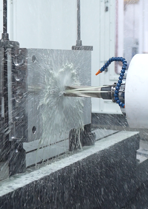
Set Nose Radius, Depth, and Feed Together
Do not select nose radius, cutting depth, and feed as separate settings. They control radial force, chip thickness, chip shape, and surface finish together.
| Radial depth, ap | Increase in bore diameter |
|---|---|
| 0.10 mm | 0.20 mm |
| 0.15 mm | 0.30 mm |
| 0.25 mm | 0.50 mm |
| 0.40 mm | 0.80 mm |
| 0.50 mm | 1.00 mm |
| 0.75 mm | 1.50 mm |
Example:
- Rough bore: 49.20 mm
- Final bore: 50.00 mm
- Total diameter stock: 0.80 mm
- Total radial stock: 0.40 mm
If 0.10 mm per side is reserved for finishing, semi-finishing removes 0.30 mm radially and leaves a 49.80 mm bore. The finishing pass then removes 0.10 mm per side.
Use a smaller nose radius when a long bar shows excessive radial force. Common insert nose radii are 0.2, 0.4, 0.8, and 1.2 mm. A 0.4 mm radius may produce a better real finish than a 0.8 mm radius if the larger insert causes chatter.
When allowance permits, a radial depth larger than the nose radius often directs more force along the bar. A smaller depth can still work with a sharp finishing insert, but chip control and radial-force problems become more likely.
If only 0.15 mm remains per side, do not increase the cut only to satisfy a general rule. Use a smaller nose radius and a chipbreaker designed for light finishing.
Use the insert maker's feed and depth range. Feed that is too low can produce:
- Long, thin ribbons
- Built-up edge
- A rubbed surface followed by tearing
- High edge temperature during a light cut
- Chips sliding along the finished bore
When chips remain long, a moderate feed increase may improve chipbreaking. Reducing feed further often makes the chip problem worse.
Change spindle speed only when the bore has regular vibration marks or a repeating sound. Keep feed, depth, stock, coolant, and test length unchanged. A 10–15% speed change is a practical trial step, not a fixed cutting rule. Both higher and lower speed can move the process away from an unstable range.
Leave the Same Stock Along the Bore
Uneven finishing stock produces changing cutting force and changing bar deflection.
Common causes include:
- Drill wander
- A tapered rough bore
- Casting or forging movement
- Misaligned operations
- Hard spots or weld deposits
- Cross-holes and ports
- Residual-stress movement
If stock changes from 0.20 to 0.80 mm per side, maximum engagement is four times the minimum engagement. One finishing pass cannot hold a constant force under that condition.
- Rough with the shortest practical tool.
- Semi-finish to remove taper and drill wander.
- Measure the bore before the final pass.
- Leave enough stock for the finishing edge to cut cleanly.
- Use one continuous finishing feed where possible.
- Avoid dwelling in work-hardening materials.
Large housings may combine boring, drilling, reaming, milling, and tapping in one setup. Using one datum and one clamping arrangement on equipment such as the SWT-4012 horizontal boring and milling center can reduce stock and alignment changes between separate operations.
Stop Chip Packing in Blind Holes
| Condition | Likely cause | First correction |
|---|---|---|
| Long ribbons | Feed too low, wrong chipbreaker, or depth too small | Check feed, ap, nose radius, and chipbreaker range |
| Chips wrapped around the bar | Poor chip direction or narrow return space | Check head shape and bar-to-bore clearance |
| Small hard fragments | Insert edge chipping | Inspect the edge and use a tougher grade if required |
| Random longitudinal scratches | Chip recutting | Improve chipbreaking and coolant direction |
| Sudden spindle-load increase | Chip packing or edge failure | Stop and inspect the bore and cutting edge |
| Damage near the blind-hole bottom | Trapped chips or insufficient bottom clearance | Check the withdrawal path and coolant return |
Through-tool coolant usually reaches a deep cutting edge better than general flood coolant. Pressure alone is not enough. The jet must reach the cutting edge, and the space around the bar must allow chips and coolant to return. OSHA notes that metalworking fluids cool and lubricate the cut and help remove chips from the cutting zone.[4]
Horizontal spindle orientation can help chips fall away from open cavities, although it does not replace the correct insert and coolant path. This difference is discussed in ASIATOOLS' explanation of chip flow on a horizontal machining center.
On a vertical machine such as the LJ-855 vertical machining center, chips can remain inside an upward-facing blind bore. Add a safe chip-removal step when normal coolant flow cannot clear the cavity.
Support Thin Parts Without Making Them Oval
A stiff boring bar cannot correct a workpiece that bends or changes shape after unclamping.
Use:
- Tailstock support for suitable shaft work
- A steady rest or follow rest for long parts
- Bored soft jaws for greater contact area
- A full-contact collet for smaller round parts
- An internal mandrel for thin sleeves
- Fixture support close to the bore
Do not increase chuck pressure before checking part distortion. A thin ring can measure round while clamped and become oval after release.
For thin walls:
- Increase contact area before increasing clamping pressure.
- Measure the bore while clamped and after release.
- Remove stock evenly.
- Use a sharp positive insert.
- Use a smaller nose radius when surface requirements permit it.
- Support an open end that vibrates during finishing.
Diagnose the Bore With Six Measurements
Measure three depths and two directions at each depth:
| Depth | Direction A | Direction B, 90° from A |
|---|---|---|
| Entrance | Record diameter | Record diameter |
| Middle | Record diameter | Record diameter |
| Bottom | Record diameter | Record diameter |
Six readings per part and three consecutive parts produce 18 readings. That is enough to separate a repeatable taper from random chip, clamping, or measurement changes.
| Bore result | Likely cause | Check first |
|---|---|---|
| Diameter decreases steadily with depth | Static bar deflection, increasing stock, or tool wear | L/D, support position, stock, and insert condition |
| Entrance is bell-mouthed | Unstable entry or uneven entrance stock | Approach path, entry chamfer, and holder contact |
| Regular waves with a repeating sound | Chatter | Overhang, damping, speed, radius, and clamping |
| Random scratches | Chip recutting or a damaged insert | Chip form, coolant path, and cutting edge |
| Two directions differ at the same depth | Part distortion, alignment error, or machine geometry | Center height, clamping, and turret alignment |
| Bore becomes oval after release | Chuck or fixture distortion | Clamping pressure and contact area |
| All depths drift over several parts | Temperature change or tool wear | Warm-up, coolant temperature, and insert life |
| Only the deep end changes | Chip packing, stock variation, or changing deflection | Bore bottom and chip-return path |
A 0.06 mm diameter reduction over a 200 mm bore equals 0.03 mm per 100 mm. If three parts show nearly the same taper, check static deflection and stock distribution first. If the taper changes from 0.01 to 0.07 mm between parts, check chips, clamping, insert condition, and measurement repeatability.
A spring pass also provides useful evidence:
- If the first spring pass cuts and the second does not, repeatable elastic recovery is likely.
- If every spring pass removes material, check movement, heat, part recovery, and measurement.
- If the amount changes from part to part, the process is not stable enough for a fixed spring-pass routine.
Separate Heat From Bar Deflection
ISO 1 specifies 20°C as the standard reference temperature for dimensional and geometrical properties.[5]
A typical carbon steel expands by about 11–12 µm per metre for each 1°C rise. Using 11.5 µm/m·°C, a 200 mm steel dimension measured 10°C above the reference temperature changes by approximately:
11.5 × 0.2 × 10 = 23 µm = 0.023 mm
A 0.023 mm thermal change is larger than a total tolerance of 0.020 mm.
Record:
- The first, fifth, and tenth part
- Diameter at the entrance, middle, and bottom
- Machine running time
- Coolant temperature when available
- Insert cutting time
- Time between machining and measurement
If all depths move in the same direction over several parts, check machine warm-up, coolant temperature, tool wear, and inspection temperature. If only the bottom changes, check bar deflection, finishing stock, and chip packing.
NIST testing has measured micrometre-level tool-to-workpiece thermal drift in machine tools.[6]
Apply Offsets Only After Three Repeatable Parts
Use a CNC offset only when the same error appears on at least three parts with stable chips, surface finish, temperature, and tool condition.
Before changing the X wear offset, confirm whether the control uses diameter or radius values:
- A 0.04 mm diameter error may require a 0.04 mm correction in diameter mode.
- The same error may require a 0.02 mm correction in radius mode.
- The correction sign depends on the control, turret position, and internal-tool orientation.
Do not use an offset to hide:
- Regular chatter marks
- Changing chip packing
- A loose bar or insert
- Fixture distortion
- Rapid tool wear
- Changing part temperature
Make a small correction, machine another part, and repeat the six-point measurement.
Use This Adjustment Order
- Measure the entrance, middle, and bottom in two directions.
- Identify taper, chatter, chip damage, part distortion, heat, or wear.
- Calculate L/D from the real support face.
- Increase bar diameter if chip clearance permits it.
- Remove unused bar, adapter, and quill extension.
- Provide about 4×D of full-contact clamping.
- Check the sleeve, tool block, turret, insert seat, and fasteners.
- Check workpiece support and clamp distortion.
- Set center height and bar rotation correctly.
- Match nose radius, radial depth, feed, and chipbreaker.
- Make the finishing stock uniform.
- Clear the chip-return path.
- Change speed only when chatter is present.
- Use carbide for more static stiffness or a damped bar for chatter control.
- Apply an offset only after three repeatable parts.
Stop the spindle and secure the machine before removing chips, measuring the bore, or reaching into the working area. OSHA identifies rotating parts and flying chips as machine hazards that require guarding and safe work procedures.[7]
Finally
Measure the real support-to-tip distance first. Keep a standard steel bar near 4×D, use about 4×D of full-contact clamping, and leave enough space for chips. A 25 mm bar shortened from 180 to 150 mm cuts theoretical deflection by about 42%; increasing diameter from 25 to 32 mm cuts it by about 63%. Use carbide for steady taper and a damped bar for regular chatter marks. Measure six points on three parts before adding compensation. If all depths drift together, check temperature and wear. If only the bottom changes, check bar bending, stock variation, and chip packing.