

Measure pressure at the fixture, wait for the initial reading to settle, record the pressure drop over a fixed time, isolate each circuit branch, and use a dial indicator to check whether the workpiece moves. A system that cannot build pressure has a different fault from one that reaches pressure and then loses it. Stable pressure is also not enough if the clamp has reached the end of its stroke or the workpiece is not seated against its locators.
Find the Failure Pattern
| Observed result | Most likely fault area | First test |
|---|---|---|
| Pressure does not reach the set value | Low pump output, relief valve open, low oil level, large external leak or blocked flow path | Test the power unit with the fixture disconnected |
| Pressure reaches the set value and then falls | Check valve, piston seal, directional valve, manifold seal or external leak | Run a timed pressure-decay test |
| Pressure takes too long to build | Restricted hose, dirty filter, partly connected coupling, trapped air or low pump flow | Measure pressure before and after the restriction while oil is flowing |
| Pressure is stable but the part moves | Clamp bottoming, wrong contact point, weak locator, poor support or insufficient force | Measure the workpiece relative to the fixed locators |
| Pressure falls only during cutting | Short pressure dip, another hydraulic branch moving, pump restart delay or accumulator discharge | Log pressure through the full machining cycle |
| Pressure loss increases after warm-up | Worn seal, valve clearance, lower hot-oil viscosity or sensor temperature drift | Repeat the same branch test when cold and warm |
A restriction mainly affects pressure while oil is flowing. Continuing pressure loss after flow has stopped normally needs a leakage path, trapped air, temperature change or movement inside the fixture.
Make the Circuit Safe
Hydraulic pressure can remain trapped after the pump and machine have stopped. ISO 4413 covers safety requirements for hydraulic systems and components used on machinery.[1]
- Stop the spindle and all machine movement.
- Isolate electrical and hydraulic power.
- Apply the site lockout and tagout procedure.
- Release pressure through the approved unloading path.
- Discharge or isolate any accumulator.
- Check every affected branch for zero pressure.
- Support clamp arms and parts that could fall or move.
OSHA requires hazardous stored or residual energy to be relieved, disconnected, restrained or otherwise made safe before servicing. Isolation must also be checked again if stored pressure can build up during the work.[2]
Do not loosen a fitting to test for pressure. Do not use a hand to locate a leak. HSE notes that serious hydraulic injection injuries are commonly linked to pressures above 100 bar, while anecdotal evidence shows that injection may occur at about 7 bar. A small puncture requires immediate medical treatment.[3]
Measure at the Fixture
Install the gauge or transducer at the pressure point that actually holds the workpiece. A gauge at the power unit cannot confirm pressure after a reducing valve, quick coupling, check valve or fixture manifold.
In a hydraulic clamping system for CNC machining centers, separate test points may be needed for the main clamp circuit, work-support circuit and positioning circuit.
| Test point | What the reading confirms | What it does not confirm |
|---|---|---|
| Power-unit outlet | Pump, regulator and relief-valve pressure | Pressure inside the fixture |
| Before a quick coupling | Supply pressure reaching the coupling | Pressure after the coupling |
| Fixture manifold | Pressure entering the clamp branches | Condition of each individual branch |
| Individual cylinder branch | Local pressure and local decay | Condition of the other clamps |
| After a pallet check valve | Pressure trapped in the disconnected fixture | Power-unit pressure |
For horizontal machines and rotary fixtures, record pressure before and after indexing. On a machine such as the WJ-800 horizontal machining center, one pump-side value cannot show whether the fixture pressure changed after rotation or multi-face machining.
Use the Right Instrument
ISO 9110-2 gives procedures for measuring average steady hydraulic pressure and estimating measurement uncertainty in closed conduits.[4]
| Test requirement | Poor choice | Better choice |
|---|---|---|
| Measure a 5 bar change near 180 bar | 0–600 bar mechanical gauge | Calibrated 0–250 bar gauge or transducer |
| Measure a 1 bar change | Instrument error close to 1 bar | Total measurement uncertainty clearly below 1 bar |
| Capture a 100 ms pressure dip | One sample per second | Sampling interval shorter than the pressure event |
| Check the machine display | Reference gauge on another circuit point | Reference gauge on the same test port |
- Check that the gauge returns to zero after pressure is released.
- Match the PLC pressure range to the transducer range.
- Check the sensor response time, not only its accuracy.
- Use the same instrument for baseline and fault tests where possible.
- Record oil or fixture temperature with every pressure result.
Run the Decay Test
Use the same workpiece, clamp sequence, pressure setting, hose arrangement, valve position and temperature for each comparison.
| Test point | Record | Fault information |
|---|---|---|
| Before clamping | Residual pressure | Return circuit or valve not fully releasing |
| Clamp starts moving | Pressure and elapsed time | Restriction, friction, trapped air or low flow |
| Clamp contacts the part | Contact pressure | End of free piston travel |
| Target pressure reached | Maximum pressure and build time | Pump and regulator performance |
| Pump stops | Pump-stop pressure | Initial hose, valve and clamp movement |
| Reading becomes stable | Stable starting pressure | Start of the formal decay test |
| During holding | Pressure at fixed times | Decay rate and curve shape |
| End of test | Final pressure and temperature | Total pressure loss under the test condition |
Example recording points are 5 seconds, 30 seconds, 60 seconds and 5 minutes. These are test intervals, not pass-or-fail limits. A disconnected fixture that must hold for two hours needs a test covering that holding time.
Run at least three repeat cycles. Three similar curves suggest a fixed leakage path. Large differences between cycles point toward trapped air, dirt moving on a valve seat, an unstable coupling or changing mechanical contact.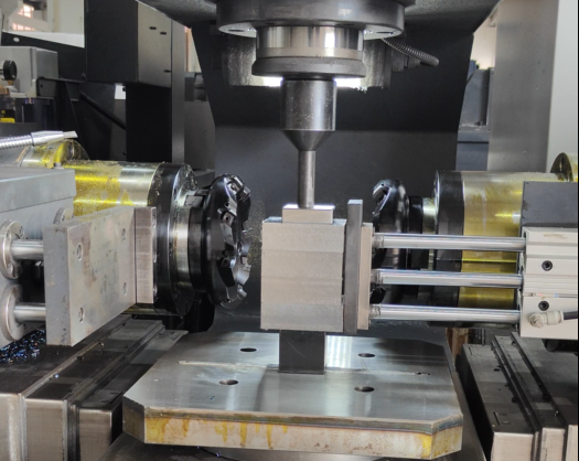
Calculate the Pressure Loss
Pressure loss = stable starting pressure − final pressure
Percentage loss = pressure loss ÷ stable starting pressure × 100
Average decay rate = pressure loss ÷ test time
Example:
- Stable starting pressure: 210 bar
- Pressure after 60 seconds: 195 bar
- Pressure loss: 15 bar
- Percentage loss: 15 ÷ 210 × 100 = 7.1%
- Average decay rate: 15 ÷ 60 = 0.25 bar per second
Use the result to compare the same fixture before and after a repair. Do not use it as a universal acceptance limit.
| Example curve | Stable start | After 60 seconds | After 5 minutes | Likely direction |
|---|---|---|---|---|
| Short settling, then stable | 200 bar | 197 bar | 196 bar | Check normal fixture baseline |
| Small continuous leak | 200 bar | 190 bar | 168 bar | Check seals and low-leak valves |
| Large leakage path | 200 bar | 145 bar | 40 bar | Check open valve, coupling or major seal failure |
A small circuit may show a fast pressure drop from a very small oil loss. A larger circuit with long hoses or an accumulator may lose more oil before the gauge changes by the same number of bar.
Read the Pressure Curve
| Curve shape | Check next |
|---|---|
| Immediate fall close to zero | Open flow path, failed coupling, open valve or major external leak |
| Fast fall followed by a stable level | Air, hose movement, valve seating, clamp seating or accumulator response |
| Slow fall that does not stop | Piston seal, check valve, directional valve or manifold leakage |
| Random downward steps | Dirt on a valve seat, intermittent valve movement or mechanical slip |
| Repeated rise and fall | Pump restarting between pressure-switch limits |
| Pressure rises after isolation | Trapped oil heating, accumulator fault or missing thermal relief |
| Cold test passes, warm test fails | Seal wear, valve clearance, oil viscosity or sensor temperature drift |
Rule Out False Pressure Loss
| Cause | Typical evidence | Confirmation test |
|---|---|---|
| Trapped air | Jerky motion, slow build time, pressure rebound and poor repeatability | Bleed the circuit and repeat three cycles |
| Hose movement | Short initial drop followed by a stable pressure | Compare with a shorter rated test hose |
| Clamp seating | Pressure falls while the arm or contact pad continues moving | Measure clamp-arm position during the hold test |
| Workpiece seating | Pressure changes while chips, burrs or a rough face compress | Clean contact faces and repeat with a known flat test block |
| Sensor error | Machine display changes while a reference gauge remains stable | Compare both instruments at the same port |
| Temperature | Repeatable difference between cold and warm tests | Record oil temperature with the same pressure and hold time |
Example of a temperature-sensitive fault:
| Condition | Oil temperature | Stable start | After 60 seconds | After 5 minutes |
|---|---|---|---|---|
| Cold fixture | 22°C | 200 bar | 196 bar | 192 bar |
| Warm fixture | 48°C | 200 bar | 182 bar | 158 bar |
The warm test loses 42 bar in five minutes compared with 8 bar when cold. Isolate the branches while the fixture is warm. The result may come from a worn cylinder seal, valve clearance, manifold leakage or sensor drift.
Isolate the Leaking Branch
- Test the power unit with an approved service circuit.
- Add the main hose and repeat the test.
- Add the quick coupling and compare both sides.
- Test the fixture manifold with all clamp branches isolated.
- Add the common valve block.
- Connect one clamp branch at a time.
- Repeat the same pressure and hold time after each connection.
| Connected section | Starting pressure | Pressure after 5 minutes | Change from previous test |
|---|---|---|---|
| Power-unit test circuit | 200 bar | 199 bar | Reference |
| Main hose added | 200 bar | 198 bar | 1 bar |
| Quick coupling added | 200 bar | 197 bar | 1 bar |
| Fixture manifold added | 200 bar | 196 bar | 1 bar |
| Clamp A added | 200 bar | 195 bar | 1 bar |
| Clamp B added | 200 bar | 159 bar | 36 bar |
Clamp B, its valve, its hose or its manifold passage contains a major leakage path. Continue testing the remaining branches because several smaller leaks can exist at the same time.
A large pressure difference across a hose or coupling while oil is moving indicates a restriction. Once flow stops, a simple hose length cannot maintain a pressure difference unless a valve or trapped section separates the two test points.
Confirm the Failed Component
| Component | Evidence | Confirmation |
|---|---|---|
| External fitting or hose | Fresh oil appears during pressure build or holding | Clean, dry and retest from a safe distance |
| Rod seal | Oil film forms around the rod during movement | Inspect rod scratches, alignment, wiper and side load |
| Piston seal | One cylinder drifts with no external oil | Isolate the branch and measure the opposite chamber where the circuit allows it |
| Static manifold seal | Pressure passes into a return or low-pressure passage without an external leak | Test manifold ports separately using the hydraulic drawing |
| Check valve | Downstream pressure falls while upstream pressure remains stable | Isolate the valve and inspect its seat, spring and sealing part |
| Directional valve | Several clamp branches lose pressure together | Isolate the common valve and repeat the test |
| Relief valve | Connected system cannot reach pressure or continuously returns oil | Check return flow and setting while the pump is running |
| Reducing valve | Inlet pressure is stable while outlet pressure drifts | Isolate downstream clamps and confirm whether the valve is relieving or non-relieving |
| Accumulator | Frequent pump cycling, short pressure support or unexpected pressure rise | Check precharge, bladder or piston seal, isolation valve and connection point |
A piston-seal leak may not create visible return flow if the opposite cylinder chamber is blocked or pressurized. Use the circuit diagram before using return flow as proof.
Do not install a larger accumulator to hide a leak. It may delay the pressure drop without repairing the valve or seal.
Check Clamp Stroke and Force
Mark the clamp position at four points:
- Fully released
- First contact with the workpiece
- Full hydraulic pressure
- End of machining
The piston must have usable stroke remaining after contact. Full gauge pressure can appear when the piston reaches its mechanical stop, even if the clamp pad is not applying the required force.
Check for chips under the workpiece, a missing contact bolt, a bent arm, a worn pivot, an incorrect workpiece height or contact with the fixture body.
Hydraulic force = pressure × effective piston area
NIST lists 1 bar as exactly 100,000 pascals. This is equal to 0.1 N/mm².[5]
| Pressure | Pressure in N/mm² | Force with 350 mm² piston area | Force remaining |
|---|---|---|---|
| 200 bar | 20 N/mm² | 7,000 N | 100% |
| 180 bar | 18 N/mm² | 6,300 N | 90% |
| 160 bar | 16 N/mm² | 5,600 N | 80% |
| 150 bar | 15 N/mm² | 5,250 N | 75% |
| 120 bar | 12 N/mm² | 4,200 N | 60% |
For rod-side pressure:
Pulling force = pressure × (piston area − rod area)
Swing clamps and lever clamps need the manufacturer’s force chart for the fitted arm length. The method used to set hydraulic clamping pressure for mold steel blocks should include cutting load, clamp geometry, solid stops and allowed part deformation.
Measure Workpiece Movement
Place dial indicators in the directions the part can lift, slide or rotate:
- Top surface near a possible lift point
- Side face opposite the main cutting force
- Thin wall or unsupported span
- Fixture plate relative to the machine table
- Clamp arm relative to the fixture body
Use a measurement resolution smaller than the permitted movement and the part tolerance.
| Reading under load | Reading after load removal | Likely fault |
|---|---|---|
| 0.030 mm | 0.004 mm | Mainly elastic bending |
| 0.030 mm | 0.026 mm | Workpiece, locator or fixture slip |
| 0.020, 0.040 and 0.070 mm over three cycles | Residual shift grows after each cycle | Progressive slip, loose locator or chip buildup |
Inspect locator pins, support pads, locating holes and workpiece faces for chips, burrs, wear and loose fasteners. A part can be clamped while touching only two of three intended support points.
On rotary machining, compare fixture movement with the machine-axis and probe results. The same separation is needed when checking datum shift caused by clamping, B-axis position or probe error.
Workpiece vibration does not always come from pressure loss. Tool overhang, spindle runout and unstable cutting parameters should also be checked against common side-milling chatter causes.
A work support should contact and support the position established by the fixed locators. The support type determines whether it contacts before or after light initial clamping. Follow the component maker’s circuit sequence before applying heavy clamp or cutting load.
Set Alarm and Stop Pressure
Calculate the minimum pressure from the required clamp force:
Required pressure = rated pressure × required force ÷ rated force
Example:
- Rated force: 40 kN at 250 bar
- Required force: 24 kN
- Calculated pressure: 250 × 24 ÷ 40 = 150 bar
Do not set the machine stop point at exactly 150 bar. Add margin for sensor error, normal pressure ripple, dynamic cutting load and unequal force between clamps.
| Control value | Example | Use |
|---|---|---|
| Normal operating pressure | 220 bar | Normal production setting |
| Warning pressure | 185 bar | Record deterioration before stopping |
| Machine-stop pressure | 170 bar | Stop before reaching the calculated minimum |
| Calculated minimum | 150 bar | Minimum before adding control margin |
| Normal pressure ripple | ±3 bar | Prevent false alarms from normal variation |
| Sensor error used in the example | ±1 bar | Included in the margin |
The values are examples, not default settings. Use the actual clamp data, cutting load, locator capacity and workpiece test result.
Record Pressure During Cutting
A fixture can pass a static test and still lose pressure for a short time during:
- Directional-valve switching
- Work-support locking
- Pallet or rotary-table indexing
- Movement of another hydraulic branch
- Pump restart
- Accumulator discharge
- Heavy tool entry
- Interrupted cutting
Log pressure with the valve command, program block, clamp-position signal, spindle load, feed rate and workpiece indicator reading. One sample per second cannot show a 100 ms pressure dip.
When several faces can be machined in one setup, record fixture pressure before and after rotation. Reducing unnecessary re-clamping in mold-base machining also reduces the number of times the datum, clamp contact and hydraulic connection must be re-established.
The low-pressure response must be chosen through machine risk assessment. ISO 12100 provides a method for identifying hazards and reducing machine risk.[6]
The safe response may stop feed, stop the spindle, block the next program step, prevent axis movement or perform a tested retract. Do not automatically move the axes after clamp pressure is lost unless that movement has been tested as safe.
When pressure monitoring performs a safety function, ISO 13849-1 provides methods and requirements for the design and integration of safety-related control parts, including hydraulic and programmable systems.[7]
Prove the Repair
- Compare the installed gauge with the reference instrument.
- Repeat the cold pressure-decay test.
- Repeat the test at normal operating temperature.
- Check clamp stroke after workpiece contact.
- Check all locator and support contact points.
- Log the lowest pressure during the machining cycle.
- Measure workpiece movement during the heaviest cut.
- Inspect the finished dimensions and surface condition.
- Record the repaired part, test temperature and final decay rate.
ISO 13849-2 specifies validation of safety functions by analysis and testing. A low-pressure interlock should be tested with the fault conditions it is intended to detect, not only during a normal cycle.[8]
Compare pallets and fixture stations separately. A combined average can hide one branch that loses pressure faster than all others.
Finally
Start with a fixture-side pressure sensor and a fixed test condition. Record the stable starting pressure, the value after 60 seconds and 5 minutes, oil temperature, clamp position and workpiece movement. A fall from 210 to 195 bar in 60 seconds equals 15 bar, 7.1% or 0.25 bar per second, but it is not a universal failure limit. Test the power unit, hose, coupling, manifold, valves and cylinders in order. After repair, repeat the cold and warm tests, record the lowest pressure during cutting, and confirm with a dial indicator that the workpiece returns to the same locator position.