

Use a drawbar force gauge made for the exact spindle interface. Clean the spindle and gauge, clamp the gauge three times unless another method is specified, and compare each reading with the machine builder’s force range. Do not use one target for every BT40, CAT40, BT50, or HSK spindle. Stop the spindle when a clean repeat test remains below the minimum, the readings are unstable, a pull stud is cracked, or an HSK holder does not contact the spindle face fully.
| Check | Required action |
|---|---|
| Spindle identity | Record the machine model, spindle part number, speed option, interface, and build date |
| Gauge setup | Match the gauge, adapter, pull stud, range, and unit to the spindle |
| Measurement | Clean the contact surfaces and record three clamp-and-release readings |
| Result | Check repeatability, OEM range, minimum force, and previous readings |
| Mechanical condition | Inspect the pull stud, gripper, taper, drawbar, springs, and release movement |
| HSK spindle | Also check push-out, gripper segments, lubrication, and flange contact |
Record the Exact Spindle Before Testing
Write down the following information before choosing a gauge or looking for a force limit:
- Machine manufacturer and model
- Machine serial number
- Spindle model or part number
- Maximum spindle speed
- Spindle build date, when available
- BT, CAT, SK, HSK, or other interface
- Pull-stud part number
- Gauge and adapter part number
BT, CAT, SK, and similar systems use a 7/24 taper shank pulled into the spindle by a retention knob or pull stud. ISO 7388-1 specifies dimensions for several 7/24 taper tool-shank forms used with automatic tool changers.[1] ASME B5.50 covers basic 7/24 taper toolholder shanks, spindle connections, and retention-knob assemblies.[2]
The LJ-855 vertical machining center uses a BT40 interface. BT40 identifies the connection size and form, but it does not provide the correct drawbar-force limit. The installed spindle, spring stack, gripper, speed option, and release system determine that value.
HSK uses a hollow taper, internal gripper segments, and flange contact. ISO 12164-1 specifies HSK tool shanks, while ISO 12164-2 specifies the matching spindle receivers.[3][4]
The GZXC-2000 five-axis machining center uses an HSK-63A interface. It needs an HSK-63A test adapter and the force and push-out values specified for its spindle. A BT40 gauge setup cannot be used.
Find the OEM Force Range
Do not use a general value based only on taper size. Two BT40 or HSK-A63 spindles can have different force ranges.
- Open the current machine service manual.
- Confirm the installed spindle-speed option.
- Check the spindle part number and build date.
- Find the normal force range and minimum allowed value.
- Confirm the required gauge adapter.
- Check whether the gauge displays force or hydraulic pressure.
- Ask the machine builder when the value is missing.
A value from another machine is not a safe substitute, even when both machines use the same holder size. Do not approve a spindle from a general BT40, CAT40, or HSK force chart.
Match the Gauge, Adapter, and Pull Stud
For a steep-taper spindle, confirm:
- The gauge adapter matches the spindle taper
- The pull-stud thread fits the adapter
- The pull-stud head matches the spindle gripper
- The gauge range is higher than the expected force
- The assembled gauge clears the table, fixture, enclosure, and tool changer
For HSK, match both the size and form. HSK-A63, HSK-F63, and HSK-A100 do not use one common test setup.
Reject or repair a gauge with:
- Hydraulic leakage
- A bent loading stem
- A damaged taper or flange
- Loose adapter parts
- A sticking pointer
- An unstable digital display
- An expired calibration or verification record
- A missing conversion chart
NIST states that metrological traceability requires a documented chain of calibrations to stated references. Traceability does not prove that the selected instrument, adapter, or setup is correct for the job.[5]
Convert the Gauge Units Correctly
| Value | Equivalent |
|---|---|
| 1 kN | 1,000 N |
| 1 kN | Approximately 224.81 lbf |
| 1 lbf | Approximately 4.448 N |
| 9.00 kN | Approximately 2,023 lbf |
| 12.00 kN | Approximately 2,698 lbf |
A gauge displaying lbf, N, kN, or daN may show force directly. A hydraulic gauge displaying psi, bar, or MPa may need the manufacturer’s conversion table.
Do not calculate force from a guessed piston area. Different gauges and adapters can use different effective areas.
Some gauges have an initial preload and do not start at zero. Record the starting value and use the gauge manufacturer’s calculation method.
Use the Same Test Conditions
- Use the same gauge or gauge model.
- Use the same adapter and pull stud.
- Use the same unit.
- Use the same clamp-and-release procedure.
- Keep the lubrication condition the same.
- Record whether the spindle is cold or warm.
- Record recent crashes, repairs, or stuck tools.
ISO 230-3 includes tests for room-temperature effects and thermal distortion caused by spindle rotation and axis movement.[6] Do not compare a cold-machine reading directly with one taken after several hours of high-speed cutting without recording the difference.
Isolate Stored Energy Before Internal Work
External gauge measurement and internal drawbar repair are different jobs. Opening the spring stack, gripper, drawbar, or release piston can expose the technician to electrical power, air pressure, hydraulic pressure, moving axes, and stored spring energy.
OSHA 29 CFR 1910.147 requires hazardous energy to be controlled when unexpected startup or released stored energy can injure a worker.[7]
- Follow the machine-specific lockout procedure.
- Isolate electrical, pneumatic, and hydraulic energy.
- Release or restrain stored pressure and spring energy.
- Verify the isolation before starting work.
- Use technicians trained on the spindle design.
Do not dismantle a Belleville spring stack because of one low gauge reading.
Clean Every Contact Surface
Clean the spindle taper, spindle face, gauge taper, gauge flange, pull stud, and accessible HSK contact areas.
Check for:
- Chips
- Dried coolant
- Grease lumps
- Corrosion
- Dents
- Scoring
- Raised metal
- Wear debris
Use strong light and a clean lint-free cloth. A clean cotton swab can help find a burr because its fibres may catch on a raised edge.
Do not run a bare finger over a damaged taper. Do not use sandpaper, grinding paste, abrasive cloth, or an unapproved stone inside the spindle. Removing metal can change the taper geometry.
Apply oil or grease only where the spindle procedure requires it. HSK and steep-taper systems may have different lubrication instructions.
Take Three Controlled Readings
- Remove the production toolholder.
- Place the machine in the required safe state.
- Clean the spindle and gauge.
- Confirm the adapter and pull stud.
- Record the gauge’s initial value.
- Support the gauge from below.
- Insert it straight into the spindle.
- Clamp the drawbar.
- Wait for the reading to settle.
- Record the result.
- Unclamp and remove the gauge.
- Repeat the cycle twice unless another method is specified.
Three readings are a practical shop method for checking repeatability, not a universal OEM requirement.
Do not insert the gauge at an angle. Do not run the spindle with the gauge installed unless both the machine builder and gauge manufacturer permit it.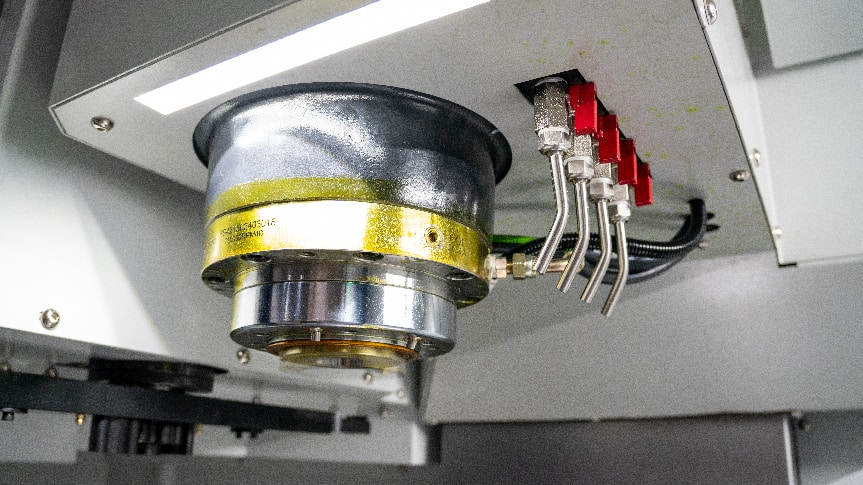
Calculate the Reading Spread
The values below are an example, not a force target:
| Calculation | Example value |
|---|---|
| First reading | 9.18 kN |
| Second reading | 9.11 kN |
| Third reading | 9.15 kN |
| Average | 9.15 kN |
| Highest minus lowest | 0.07 kN |
| Spread divided by average | Approximately 0.8% |
The readings are close together. The 0.8% figure describes only this example; it is not a universal acceptance limit. Compare the spread with the gauge manufacturer’s stated accuracy and repeatability.
Do not average readings such as 9.20, 7.65, and 8.94 kN and approve the spindle. Check for dirt, poor seating, a loose adapter, uneven gripper contact, inconsistent drawbar travel, or a sticking gauge.
Calculate the Margin Above the OEM Minimum
The next values use an imaginary OEM minimum of 9.00 kN:
| Calculation | Example value |
|---|---|
| OEM minimum | 9.00 kN |
| Measured average | 9.15 kN |
| Force above minimum | 0.15 kN |
| Margin above minimum | Approximately 1.7% |
A 9.15 kN average passes this example minimum, but the margin is small. Compare it with earlier records.
A clean repeat result of 8.62 kN would be 0.38 kN below the example minimum. It equals about 95.8% of the required value, but it still fails. A reading close to the minimum is not acceptable when it is below the limit.
Use Clear Pass, Retest, and Stop Rules
| Result | Required action |
|---|---|
| Stable and within range | Record the readings and keep the normal inspection interval |
| Within range but falling | Inspect wear points, review tool-change count, and shorten the interval |
| Below the minimum | Clean and retest; stop the spindle if the result remains low |
| Unusually high | Check the unit, starting value, adapter, gauge movement, and HSK push-out |
| Unstable | Correct the test setup before judging the spindle |
Remove the spindle from service immediately when:
- A clean repeat test remains below the minimum
- A toolholder has dropped
- A pull stud is cracked or deformed
- An HSK flange has a visible gap
- The force falls suddenly by a large amount
- A gripper finger or segment is broken
- The holder has rotated inside the spindle
- The taper has raised metal or deep scoring
- The readings remain unstable after the setup is corrected
Inspect Pull-Stud Wear and Threads
Pull-stud inspection applies to BT, CAT, SK, and other steep-taper holders. HSK holders use an internal gripping surface.
| Area | Reject conditions |
|---|---|
| Gripper contact surface | Deep grooves, dents, flat spots, rolled edges, one-sided wear, or cracks |
| Neck | Stretching, corrosion, deformation, or visible loss of diameter |
| Threads | Cross-threading, galling, cracks, damaged first threads, or looseness |
| Identification | Unknown part number, mixed geometry, or uncertain machine compatibility |
Do not grind or polish away a deep groove. Removing material changes the contact shape and does not restore the pull stud’s strength.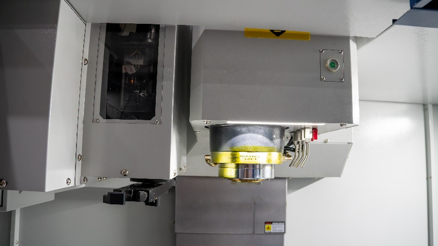
Use Contact Marks to Find the Fault
| Contact pattern | Likely checks |
|---|---|
| Even contact band | Compare with a known-good stud from the same spindle; still confirm the part number |
| Marks near one edge | Check pull-stud shape, reference length, gripper opening, and release travel |
| One-sided contact | Check for a bent stud, worn gripper, dirt, broken gripper parts, or poor holder seating |
| Deep groove or rolled edge | Replace the pull stud |
If several holders from one machine show the same unusual mark, inspect the spindle gripper. If only one holder is affected, quarantine that holder first.
Prevent Mixed Pull Studs and Holders
Pull studs that look similar can have different head angles, head diameters, neck diameters, reference lengths, threads, pilot dimensions, and coolant passages.
A pull stud that screws into the holder may still be wrong for the spindle. Check the machine builder’s part number and all critical dimensions.
Use the torque stated by the pull-stud or toolholder manufacturer. Do not use an impact wrench, hammer, extension pipe, or estimated hand torque.
Store different holder and pull-stud families separately. The article on HSK, BT, and SK toolholder organization shows how labels and separated storage positions reduce mixed-tooling errors. A suitable CNC toolholder cart also keeps precision tapers away from loose metal parts.
Separate Fretting from Dirt and Corrosion
Inspect the spindle and holder taper for scoring, dents, raised edges, chips, corrosion, uneven polishing, coolant deposits, signs of holder rotation, and red-brown or dark debris.
Red-brown colour alone does not prove fretting. Fretting is more likely when the marks include polishing, pits, scratches, wear bands, or matching damage on the spindle and holder.
NASA fretting tests have found metallic and oxide debris, scratches, plastic deformation, cracks, and pits in damaged metal contact areas.[8]
Remove a damaged holder before it marks the spindle. Inspect the spindle before returning other holders to service.
Separate Gripper, Spring, and Release Faults
| Finding | Check first |
|---|---|
| Low force with normal tool changes | Springs, gripper wear, drawbar wear, pull stud, and lubrication |
| Normal force with difficult release | Release travel, taper damage, deposits, temperature, and pull-stud condition |
| Sudden force drop | Broken disc spring, damaged gripper, drawbar damage, or an assembly error |
| Slow force drop | Spring fatigue, gripper wear, drawbar wear, contamination, and poor lubrication |
| Unstable force | Gauge, adapter, seating, dirt, gripper movement, and drawbar travel |
| Tool drops during a change | Force, changer alignment, release timing, sensors, and machine-specific pressure settings |
The CNC spindle pull-claw configurations include different BT sizes, threads, and claw forms. Match the spindle model, drawbar thread, pull-stud angle, gripper length, speed, and release movement before replacing a gripper.
Check HSK Force, Push-Out, and Face Contact Together
An HSK inspection must include:
- Pull force
- Push-out
- Gripper segments
- Clamping cone
- Internal spacers and contact parts
- Seal or packing ring
- Specified lubrication
- Holder orientation
- Taper contact
- Full flange contact
Do not run the spindle when the holder flange has a visible gap.
An incorrect push-out value can cause low force, an unusually high gauge reading, incomplete clamping, or difficult release. The value and measurement reference are spindle-specific. Do not copy a dimension from another HSK-A63 spindle.
After any adjustment, recheck push-out, pull force, flange contact, and release movement. Use only the specified lubricant. Do not mix greases, blow compressed air into the clamping unit, wash out the lubricant with an unapproved cleaner, or pack the mechanism with excess grease.
Check Runout, Balance, and Bearings When Force Passes
A normal drawbar-force result does not rule out:
- A worn cutting tool
- Excessive tool overhang
- Tool or holder runout
- An unbalanced tool assembly
- Excessive spindle speed
- Poor workholding stiffness
- Taper damage
- Spindle vibration
- Bearing damage
ISO 230-7 treats spindle axis error motion and speed-related axis shift as separate machine-tool properties. A drawbar force gauge does not measure these errors.[9]
When clamping force passes but chatter remains, use the checks in tool chatter causes and fixes to separate tool, holder, process, fixture, and spindle problems.
Set the Inspection Interval by Tool-Change Count
Use the machine builder’s stated interval first. When no clear interval is given, combine calendar time with tool-change count, spindle speed, cutting load, contamination, repair history, and previous force readings.
| Machine use | Tool changes per day | Changes in 250 production days |
|---|---|---|
| Low-use toolroom machine | 100 | 25,000 |
| Two-shift production machine | 600 | 150,000 |
| Three-shift high-cycle machine | 1,500 | 375,000 |
The high-cycle example completes 15 times more tool changes than the toolroom example in the same period. Waiting the same number of months for both machines ignores this difference.
A heavy-duty horizontal machining center using large tools for interrupted roughing may also need shorter inspection intervals than a lightly loaded VMC.
Inspect immediately after a crash, dropped holder, stuck holder, changer collision, new fretting marks, repeated tool breakage, drawbar repair, gripper replacement, or an unexplained change in clamp or release sound.
Record Data That Can Show a Trend
| Record field | Illustrative entry |
|---|---|
| Machine ID | VMC-04 |
| Spindle interface | BT40 |
| Gauge ID | DFG-02 |
| Spindle condition | Warm |
| Tool-change count | 186,420 |
| Readings | 9.18, 9.11, and 9.15 kN |
| Average | 9.15 kN |
| Reading spread | 0.07 kN |
| Pull-stud condition | No crack, deep groove, or corrosion |
| Taper condition | Clean; no raised damage |
| Action | Compare with OEM limit and previous reading |
Also record the spindle model, speed option, gauge calibration status, adapter number, pull-stud part number, OEM minimum and maximum, previous result, HSK push-out when applicable, repairs, and technician name.
Do not record only the average. Individual values show whether the test was repeatable.
Use the Trend to Plan Service
The values below are examples, not a spindle specification:
| Inspection | Average force | Share of first reading | Action |
|---|---|---|---|
| January | 9.40 kN | 100.0% | Set the baseline |
| April | 9.25 kN | 98.4% | Keep the normal interval |
| July | 8.98 kN | 95.5% | Inspect wear points and shorten the interval |
| October | 8.71 kN | 92.7% | Plan service and compare with the OEM minimum |
The percentage shows change from the first reading. It does not replace the OEM limit. A stable trend still fails when every reading is below the specified minimum.
Finally
Match the gauge, adapter, and pull stud to the exact spindle; clean the taper and contact faces; and take three readings when the OEM gives no different method. In the example, 9.18, 9.11, and 9.15 kN average 9.15 kN with a 0.07 kN spread. Repeatability does not prove the spindle passes—the average must still meet the OEM minimum. Stop the spindle after a below-limit retest, a dropped holder, a cracked pull stud, a damaged gripper, or an HSK face gap. Record individual readings and tool-change count; 1,500 changes per day equals 375,000 cycles in 250 production days, so high-cycle machines need earlier checks.