A twin-head milling machine uses two spindles to cut both sides of a workpiece at the same time. With just one setup, the table can then rotate 90 degrees to complete all four sides, eliminating repeated manual handling and re-positioning.
Compared with traditional single-side milling, this approach cuts cycle time by about 50% and keeps perpendicularity and parallelism errors tightly controlled within 0.01 mm.
By sharply reducing manual intervention, it not only delivers much higher machining accuracy, but also directly doubles overall output in batch production.
Faster Output
Cutting Efficiency Doubled
Back when P20 mold steel was machined on a conventional machine, once the feed rate reached 250 mm/min, the machine would start to chatter. With cutting force concentrated on only one side, the cutter head would bite more than 4 mm deep, and even the heavy machine column could be forced into 0.02 mm of deformation.
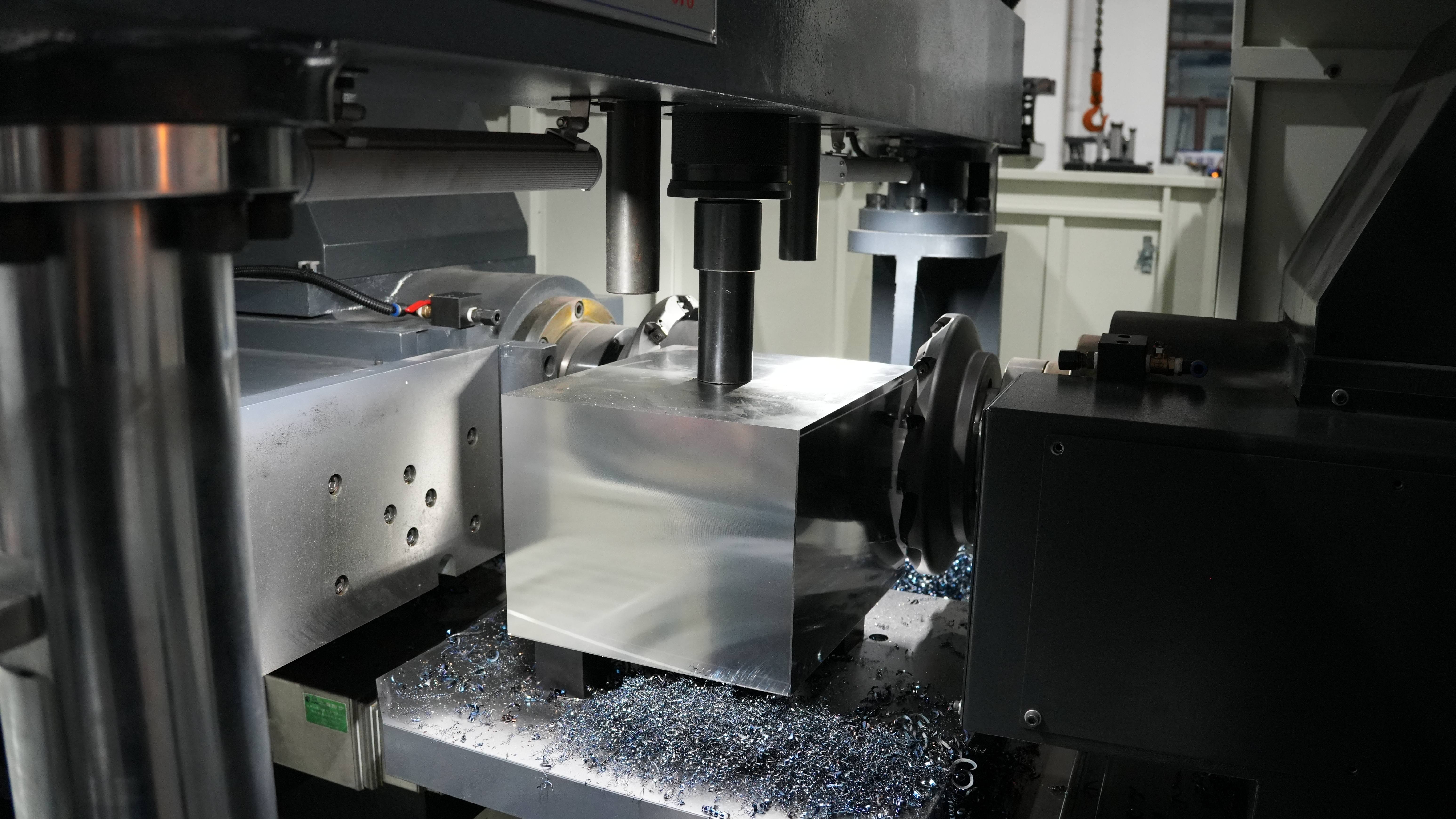
On a twin-head machine, each side carries a 22 kW high-power motor fitted with an eight-insert, 200 mm face mill. At 800 rpm, the two cutters bite into the steel block from opposite sides at the same time. The hundreds of kilograms of cutting force meet inside the workpiece and cancel each other out. Once the forces are balanced, the machine naturally runs more smoothly.
That is why the feed-rate dial on today’s control panel can be turned up confidently to 500 mm/min. With both sides cutting simultaneously, the chip volume removed in one minute jumps from 120 cm³ to 280 cm³. Chips hammer against the enclosure like a heavy downpour, and the chip conveyor underneath must run 30% faster, otherwise the machine simply cannot keep up.
The machining parameters during operation now look like this:
· Roughing depth of cut held steadily at 5 mm
· Cutter peripheral speed increased to 180 m/min
· Feed per tooth raised to 0.2 mm
· Surface finish better than 3.2 μm
Opposed cutting does more than eliminate vibration. It also changes the nature of the chips themselves. Under single-side heavy cutting, friction at the tool tip could easily push temperatures past 600°C, turning the chips dark blue from heat. That high temperature caused carbide inserts to age rapidly. With simultaneous double-side machining, the load is split evenly and the temperature distribution becomes much more uniform.
Combined with a through-coolant system running at 40 kg of pressure, the heat is stripped away immediately by the emulsion. Most of the chips landing on the conveyor are silver-white or pale yellow instead. Tool life increases by more than 40%. Over a 12-hour day shift, where four insert changes used to be necessary, now one is usually enough, which saves a great deal of downtime.
Take a block of 45 steel measuring 600 mm × 600 mm × 150 mm as an example. Under the old method, one face required three passes, and a single side alone took 24 minutes. Including manual flipping and re-alignment, finishing both ends took 65 minutes. With the current process, once zero is set, both cutters engage together and complete roughing and finishing in just 18 minutes total.
The two spindles are synchronized by microsecond-level calculations at the system level. If the left cutter hits a hard spot in the casting and current spikes instantly to 65 A, the right spindle automatically fine-tunes its speed within 2 milliseconds, keeping both sides perfectly coordinated. That synchronized drive holds parallelism between the two machined faces tightly within 0.015 mm.
When buying equipment or planning production, these are the hard indicators worth checking closely:
· Synchronization compensation accuracy between the left and right spindles
· Z-axis thermal growth under full-load operation
· Damping performance of the cast-iron machine bed
· Hydraulic fixture pressure-holding capability under heavy cutting
With double the material removal rate, piles of rough blanks on the shop floor can be turned into finished parts in just three days. One machine now does the work of two, saving not only RMB 150,000 a year in equipment depreciation, but also around RMB 100,000 a year in skilled labor costs.
When both motors start at once, peak power can reach 55 kW, which looks expensive on paper. But because total machining time is shortened by 70%, electricity consumption per part actually drops by 25%. Once the process changes, the entire rhythm of order handling and delivery speeds up with it.
As the machine becomes more capable, daily maintenance routines must also change:
· Monitor coolant concentration for the left and right spindles separately
· Clean the doubled chip accumulation on the guideway covers more frequently
· Inspect insert wear on both opposing cutter heads together
· Check backlash in the rotary table gears every three months
Compressing “Non-Cutting Time”
In most workshops, the spindle is actually cutting metal for only about 40% of a 12-hour shift. The remaining 60% is spent on hoisting, leveling, and tightening bolts. With a 500 kg P20 mold steel blank, simply using an overhead crane to position it steadily on the table can take at least 15 minutes.
On an old single-side milling machine, the most exhausting part is always flipping the block. After one face is cut, the operator has to loosen eight M24 nuts one by one, attach two heavy-duty nylon slings rated for 3 tons, lift the part, turn it over, then use a dial indicator to sweep the surface and a 2 lb copper hammer to tap parallelism back into a 0.01 mm tolerance zone.
Even for an operator with 10 years of experience, this entire flip-and-level process takes at least 30 minutes at full speed. If all four sides must be machined, as much as two full hours in a day can be wasted just turning the part over on the table. During that time, the spindle is stopped, and a CNC machine worth RMB 2 million is no more productive than scrap metal.
The CNC rotary table on a twin-head milling machine removes that problem completely. Once the workpiece is clamped, the machine can mill all four sides in one continuous sequence. A 500 kg steel block can be rotated 90 degrees in just 5 seconds by the servo motor underneath, with the locating pins locking into place precisely.
When handling forgings with uneven surfaces and machining allowance greater than 5 mm, the hydraulic automatic clamps on the table replace the old T-slot clamp plates. The moment the oil pump starts, 70 kg of hydraulic force drives four jaws with 20 mm stroke to grip the workpiece firmly. What used to require five minutes of hard manual tightening with a one-meter torque wrench now takes just 2 seconds by pressing a green button.
Let’s compare the time spent machining a standard 600 mm × 600 mm × 200 mm block on old and new equipment:
| Operation | Old Single-Side Vertical Milling | Twin-Head Milling Machine (with Rotary Table) | Time Saved |
| Initial setup and leveling | 25 min | 10 min | 60% |
| Reversing / re-leveling | 30 min × 3 = 90 min | 5 sec × 3 = 15 sec | 99% |
| Mid-process stop for measurement | 15 min | 0 min | 100% |
| Total non-cutting time | 130 min | 10 min 15 sec | 92% |
Without repeated disassembly and re-leveling, the workpiece has only one physical reference surface in the fixture from start to finish. The first machined face naturally becomes the reference for the remaining three, so dimensional tolerance and overall squareness remain steadily controlled within 0.015 mm.
Mid-process measurement used to consume a huge amount of time as well. After each cut, the operator had to slide open a 50 kg safety door and reach in with a 1-meter caliper to measure thickness. The freshly cut steel surface often still carried more than 40°C of heat, and the 0.02 mm deformation caused by thermal expansion would make the reading hard to trust.
Now, both spindles are equipped with high-precision Renishaw infrared probes. As soon as the chips are cleared, the ruby-tipped probe moves in at 3000 mm/min, touches each side 10 mm from the edge, and finishes the entire probing cycle in 15 seconds. Measurement error stays below 3 microns, and the data is sent immediately to the control system for automatic tool compensation.
As manual work decreases, the scrap rate drops sharply. In a batch of 100 identical 45 steel hydraulic valve blocks, two or three parts used to be scrapped simply because an operator misread a graduation while indicating the part. Now the zero point is locked into the FANUC control system, and the dimensional variation across 100 parts stays below 0.005 mm.
Even the 5-ton overhead crane now sits mostly idle. In the past, three single-side machines had to share one crane, and operators often stood waiting 20 minutes just for lifting access. With the new one-setup, four-side process, crane usage drops from 40 lifts per day to 10, and the 1.5-meter-wide aisle becomes much smoother for internal transport.
For a custom order of 300 flanges, an old machine could produce only 20 pieces in 24 hours on a two-shift schedule once all the loading and unloading time was included. The twin-head machine, free from repeated handling and waiting, can turn out 55 pieces in the same time, pulling the delivery date forward by a full week.
Faster Per Part, More Stable in Batches
On a single-side machine, a 350 kg mold steel block is clamped by hand. Using an 80 cm wrench, an operator can tighten it to around 120 N·m. But by 4 p.m., when the workshop temperature reaches 38°C, his arms are already fatigued, and the same wrench may only produce 80 N·m of clamping force.
When the nuts are not tightened consistently, the heavy block can begin to slip by microns during cutting. Once the cutter digs 6 mm deeper, the freshly machined bright surface may drift by 0.03 mm. No matter how expensive the machine is, if clamping depends entirely on human effort, the first part and the hundredth part will never be identical.
On the hydraulic station beneath the machine, the pressure gauge stays fixed at 6 MPa. Whether it is the first part at 8 a.m. or the hundredth part at 2 a.m., the clamping force at the four corners remains an identical 1,500 kg with no fluctuation in oil pressure.
Once the process stops depending on human feel, the force delivered by the hydraulic pump ensures the workpiece sits in exactly the same position every time.
Without operators repeatedly lifting and turning the workpiece, production speed naturally rises. In the old single-side process, over a 12-hour shift, at least 90 minutes of spindle time could be lost simply because the operator needed water, had to wipe away sweat, or stepped away briefly. The machine, however, does not get tired. As long as insert wear remains below the 0.15 mm limit, the spindle can continue cutting at 800 rpm exactly as programmed.
Take a P20 cast-iron automotive engine block as an example. For an order of 200 pieces, one operator watching one single-spindle machine on day and night shifts could produce only 45 parts in 72 hours. Each part also had to be checked on a CMM to make sure poor clamping had not caused rejection. On a twin-head opposed milling machine, the same 72 hours can produce 180 parts.
For high-volume orders, the real advantages show up clearly in the numbers:
· Thickness variation between the first part and the 200th is kept within 0.008 mm
· The daily 90 minutes of downtime caused by operator fatigue is eliminated
· Day-shift and night-shift output differs by fewer than two parts
· Machine stoppage caused by insert chipping drops by 65%
In the past, parts coming off old machines were inconsistent: some wider at the top than the bottom, others carrying a 0.05 mm taper. The grinding department had to sweep each piece with a dial indicator before starting work. Now, the square blocks coming off the twin-head machine hold perpendicularity on all four sides within 0.01 mm. Downstream operators can load them with complete confidence.
Because the blanks are now so regular, the grinding machine can safely take a 0.02 mm first pass with a 300 mm wheel without hesitation. The half hour once spent correcting errors from the previous process disappears. Material flow through the entire workshop becomes dramatically smoother.
The more stable the output from the first process, the faster every downstream operation can run.
Production planning becomes much easier too. Supervisors no longer have to guess whether a fast veteran or a slower trainee is on shift. If the G-code calls for a feed rate of 400 mm/min, the machine will always finish a 600 mm cutting path in exactly 22 minutes 30 seconds. If the schedule says 500 parts must be ready by noon the day after tomorrow, the truck can arrive an hour early and still be loaded on time.
The chip conveyor beside the machine runs around the clock, discharging silver-yellow chips continuously. A single machine can remove 400 kg of scrap metal in one day, and the AGV in the aisle has to come by every four hours to collect a full bin. Once the human bottlenecks are eliminated, effective machine utilization rises sharply from a barely acceptable 60% to over 85%.
Less Handling & Better Safety
The Turning Problem
On the cast-iron table of an ordinary milling machine lies a mold steel block measuring 800 × 600 × 150 mm. It weighs 560 kg, about as much as a fully grown buffalo.
As the machine comes to a stop, the operator walks over on steel footplates slick with cutting fluid. He grabs the air gun and blasts the table with high-pressure air at 0.8 MPa. It screams at 85 dB while blowing away chips that are still around 80°C.
He then pulls out a 1.2-meter hollow steel pipe, slips it over the fixture wrench, and leans his full body weight into it to fight against 150 N·m of clamping torque. Finally, the jaws of the two heavy clamps release with a hard metallic thud.
Then comes the lifting sequence:
· Call down the 5-ton overhead crane by remote
· Pull down the 12 mm steel wire rope coated in black grease
· Screw the lifting eye bit by bit into the 30 mm-deep threaded hole in the side of the steel block
· Press the control button and raise the hook slowly at 2 m/min
The 560 kg block hangs in mid-air like a suspended hammer. The operator and his assistant, both wearing cut-resistant gloves, must push it by hand and laboriously rotate it 90 degrees in the air. As the center of gravity shifts, the yellow nylon sling groans under the load.
The workshop floor is always slippery. If the sling slips by even 2 cm while turning a load like this, the block can crash downward. A drop of just 10 cm is enough to dent the machine table by 2 mm, causing serious damage to equipment worth hundreds of thousands of yuan.
Even after the part is turned, it cannot be set down immediately. The operator must spend 5 minutes brushing the support blocks clean. If even a 0.02 mm chip, as fine as a hair, is left underneath, it acts like a coin under a table leg. Once the 560 kg steel block is cut, the whole part may be dimensionally off and scrapped.
The crane lowers the block at a painfully slow 0.5 m/min. The operator watches the dial indicator intently, copper hammer in hand, weighing 1.5 kg. One tap, then a glance at the needle. Another tap, then another check. After more than 20 strikes, the indicator finally settles within 0.01 mm.
Then the long pipe goes back onto the wrench again, and the fixture is tightened down with full force. Stop the machine, release the clamps, lift the part, flip it, clean the table, lower it, tap to re-level, lock it again. By the time the full sequence is done, the operator is drenched in sweat and 25 minutes have passed on the clock.
The cost of that process is brutal:
· 100 minutes of pure turning time wasted per steel plate
· 0.05 mm of dimensional deviation accumulated through repeated flipping
· Two skilled operators sweating out the equivalent of two bottles of mineral water
· A machine worth hundreds of thousands sitting idle for 40% of the day
By the end of a single 8-hour shift, the operator has fought with more than 3 tons of steel over and over again. In southern machining factories, veteran milling operators with 10 years on the job often show clear lower-back and shoulder strain on X-rays. The stop-and-go physical labor also makes fatigue and lapses in attention much more likely after 4 p.m.
Walk over to the twin-head milling machine at the other end of the shop, and the crane remote is hanging silently on the wall collecting dust. The heavy block is placed once into the machine’s built-in hydraulic fixture. In 2 seconds, the system applies 250 bar of pressure and grips the steel like a giant hand. On both sides, 160 mm face mills begin cutting into the workpiece simultaneously.
With the cutters feeding at 800 mm/min, each pass removes 5 mm of material. Once two sides are finished, the internal graduated rotary table turns automatically and rotates the block 90 degrees in 12 seconds, after which the cutters immediately begin machining the remaining two sides.
The operator now stands outside the 15 mm blast-resistant viewing window with a 500 ml insulated cup in hand, watching the numbers move on the screen. From the moment the 560 kg block was loaded in that morning, it never leaves the fixture again.
Process Advantages
Through the 15 mm blast-resistant viewing window, the operator watches the 560 kg block held rigidly by hydraulic clamps. On both sides, 160 mm cutter heads move inward together with a low roar.
On the old machine, a single cutter head drove into the material from one side. A 50 kW spindle motor created a huge lateral force that shoved the workpiece in the opposite direction.
Even with the hydraulic clamps applying an impressive 250 bar, the uncut side of the block would still lift slightly. A dial indicator with 0.01 mm resolution would show the underside rising by 0.03 mm.
With simultaneous two-side cutting, however, the left cutter removes 5 mm and the right cutter removes 5 mm at the same time. The opposing forces balance each other in the center of the workpiece, like two 80 kg men pushing against each other head-on.
With no one-sided force, the 560 kg steel block stays flat and stable on the table without the slightest movement. The high-frequency vibration disappears, and the 12 carbide inserts mounted around the cutter head gain about 30% more life.
Every time the machine finishes one 800 × 600 × 150 mm P20 mold steel plate, the workshop clerk adds another comparison entry to the machining log:
| Process Data Comparison | Old Single-Side Milling Machine | Simultaneous Twin-Head Milling | Difference |
| Number of times the fixture must be loosened and tightened manually | 4 | 1 | 75% less heavy manual work |
| Pure cutting machine runtime | 160 min | 60 min | 100 min saved |
| Parallelism error after machining four side faces | 0.05 mm | 0.01 mm | 5× improvement in accuracy |
| Number of inserts consumed per steel plate | 24 | 16 | Major reduction in consumable cost |
Once the workpiece rotates itself 90 degrees inside the machine, the two cutter heads continue with the remaining short edges. After all four sides are completed in one continuous cycle, the squareness error at the four corners is held within 0.015 mm.
A 0.015 mm error is roughly one-fifth the thickness of a human hair. When these parts move to the finish-machining department, the next operator no longer has to search the floor for 0.01 mm copper shims just to re-level the workpiece.
Cutting steel at high speed can instantly generate temperatures close to 600°C. Under single-side machining, one side of the plate can exceed 100°C while the opposite side remains at ambient 20°C. A 560 kg steel block then warps from uneven heating, and dimensions can drift by 0.04 mm on the spot.
Simultaneous two-side machining raises the temperature on both sides together. With emulsion coolant cascading down at 80 liters per minute, thermal expansion remains symmetrical from left to right.
The carbide inserts spin at 600 rpm, and the blue chips they throw down pound the machine base like a storm. A dual-screw chip conveyor underneath runs at full speed and removes 15 kg of hot chips per minute.
In the past, after machining one 800 mm plate, the operator had to spend a full 10 minutes bent over the machine, shoveling out scrap metal by hand. The chips could fill two 120-liter carts.
Now the chips fall directly through the conveyor into a large recycling bin outside the shop. A built-in high-pressure wash gun cleans the table with 5 MPa water pressure, leaving not even a 0.05 mm particle behind.
At final inspection, the quality inspector places an 800 mm, grade-0 granite straightedge worth RMB 3,000 against the side of the steel block. A strong flashlight shone from behind reveals no visible gap at all.
A dial indicator swept across the 600 mm width shows no more than two divisions of movement, which converts to 0.02 mm. On the old machine, reaching that result required half an hour of tapping and shimming with a 1.5 kg copper hammer.
The production numbers on the workshop’s output board change completely as well. Under the old method, after a full 8-hour struggle, two sweating skilled operators could produce at most 4 qualified P20 mold plates.
With the twin-head machine, one senior operator and one apprentice with six months of experience can easily complete 11 plates before the 5 p.m. shift ends, nearly tripling output in real terms.
Safe Production
Walk up to an ordinary single-head machine and you will see burn holes scattered across the operator’s blue cotton uniform.
As the carbide inserts bite into cast iron at 600 rpm, metal chips can shoot to nearly 600°C within a second. Blue-hot fragments burst outward like shrapnel in unpredictable directions.
Even if the operator stands 2 meters away in the aisle, a fingernail-sized chip can still pierce clothing with ease. The old machine is protected only by a 1.2 mm sheet-metal splash guard, which does almost nothing to stop sharp flying debris.
“I’ve been in machining for 15 years, and I’ve had more than 20 stitches in my arms from chips flying off the table.”
The operator rolls up his left sleeve, revealing a dark red scar about 4 cm long on his forearm.
Now shift your attention to the twin-head milling machine on the other side of the shop, and the sparks are gone completely. The entire machining area is enclosed inside a fully sealed steel housing measuring 3 m long, 2.5 m wide, and 2 m high.
The front observation doors are fitted with 15 mm thick blast-resistant glass. Just last Wednesday afternoon, a 300 g insert fragment hit hard steel, snapped off, and slammed into the transparent viewing window at 50 m/s.
It left only a white mark less than 2 mm deep on the glass, without even producing a hairline crack. On an older unenclosed machine, that broken fragment could easily have struck a worker walking through the aisle.
Old machines also leave the entire surrounding area in a dangerous mess:
· Cutting fluid splashes across the floor and builds into 3 mm-thick black sludge
· Workers have to wear 30 dB noise-reduction earplugs all day to endure the motor whine
· Every two hours, someone has to use a half-meter metal hook to drag out red-hot chips
The sealed enclosure blocks the dangerous flying metal and also traps the noise. Machine noise that once reached 85 dB, loud enough that people had to shout face-to-face, is reduced to below 65 dB.
The first thing the operator does every morning now is toss his sweaty silicone earplugs into a drawer. An exhaust fan on top of the machine removes 800 m³ of moisture-laden air per hour, so the workshop no longer smells of hot machine oil.
The 560 kg steel block hanging overhead on a crane is the real time bomb in any workshop. Under the old process, even a single damaged nylon fiber in a sling could lead to disaster.
Last year, at a neighboring mold factory, the wire rope on a 3-ton crane slipped during handling. A falling steel billet smashed a deep crater into a 15 cm concrete floor and crushed the top of a worker’s right foot.
With the twin-head machine, the crane is needed only once per shift: load the block at 8 a.m., unload it at 5 p.m. Everything in between, including all turning operations, is done by the hydraulic rotary table underneath.
In the past, the operator had to climb around the oily cast-iron table all day to align threaded holes, bending over again and again to attach lifting eyes and loosen bolts as many as 40 times a day. One misstep could leave his shin bruised badly against the sharp edge of the machine.
The large graduated rotary table inside the machine is designed for a load capacity of up to 10 tons. When it rotates a workpiece weighing several hundred kilograms, it moves so smoothly that even a cup of water on the table would not spill a drop.
If a summer thunderstorm causes a power outage, or if the main air line in the shop leaks and pressure drops, the machine’s internal safety lock valve activates within 0.2 seconds.
Even under those conditions, the 250 bar hydraulic clamps continue gripping the 560 kg mold steel block firmly, and the pressure gauge does not drop at all. The workpiece will not loosen or fall.
Safety features are built into every part of the machine:
· Both doors are fitted with interlocks, and the cutters cannot rotate unless the doors are fully closed
· All panel buttons operate at 24 V safety voltage and remain safe even with wet hands
· The floor around the machine is covered with grooved aluminum anti-slip plates with a friction coefficient above 0.6
Without the constant danger of lifting and flipping heavy parts overhead, and without having to stay on edge to dodge red-hot flying chips, the operator drinks more water, needs far fewer smoke breaks, and works in a much steadier condition.
Once physical strain is reduced, low-level mistakes such as pressing the wrong button or misreading a drawing also fall sharply. On last month’s scrap report, the rejection rate from dimensional machining errors dropped from 5 per thousand all the way to zero.
The green-painted floor around the machine now needs to be swept with sawdust only once a week, and no one slides half a meter forward when walking across it. Even the operator’s RMB 200 steel-toe safety shoes remain clean after six months of wear.
Precision & Squaring Accuracy
Saying Goodbye to Error
A 500 mm × 500 mm square blank must be removed and re-clamped four times on an ordinary single-spindle milling machine. Every time the vise tightens down, its 2,000 kg clamping force causes a small elastic deformation in the steel plate that is invisible to the naked eye.
After the first face is milled and set back down on the base, even if the operator blows the surface clean with compressed air, a 0.01 mm chip trapped underneath will tilt the entire workpiece. When the cutter head accelerates to 1,500 rpm to machine the second face, the new surface will immediately carry a slight wedge error of several microns.
By the time the third and fourth faces are machined, those tiny deviations accumulate like a snowball. In the end, a caliper may show a squareness error of 0.05 mm or more. When the part moves to the CNC machining center for hole drilling and finish work, the machine often has to sit idle while an operator spends another 20 minutes indicating it in again.
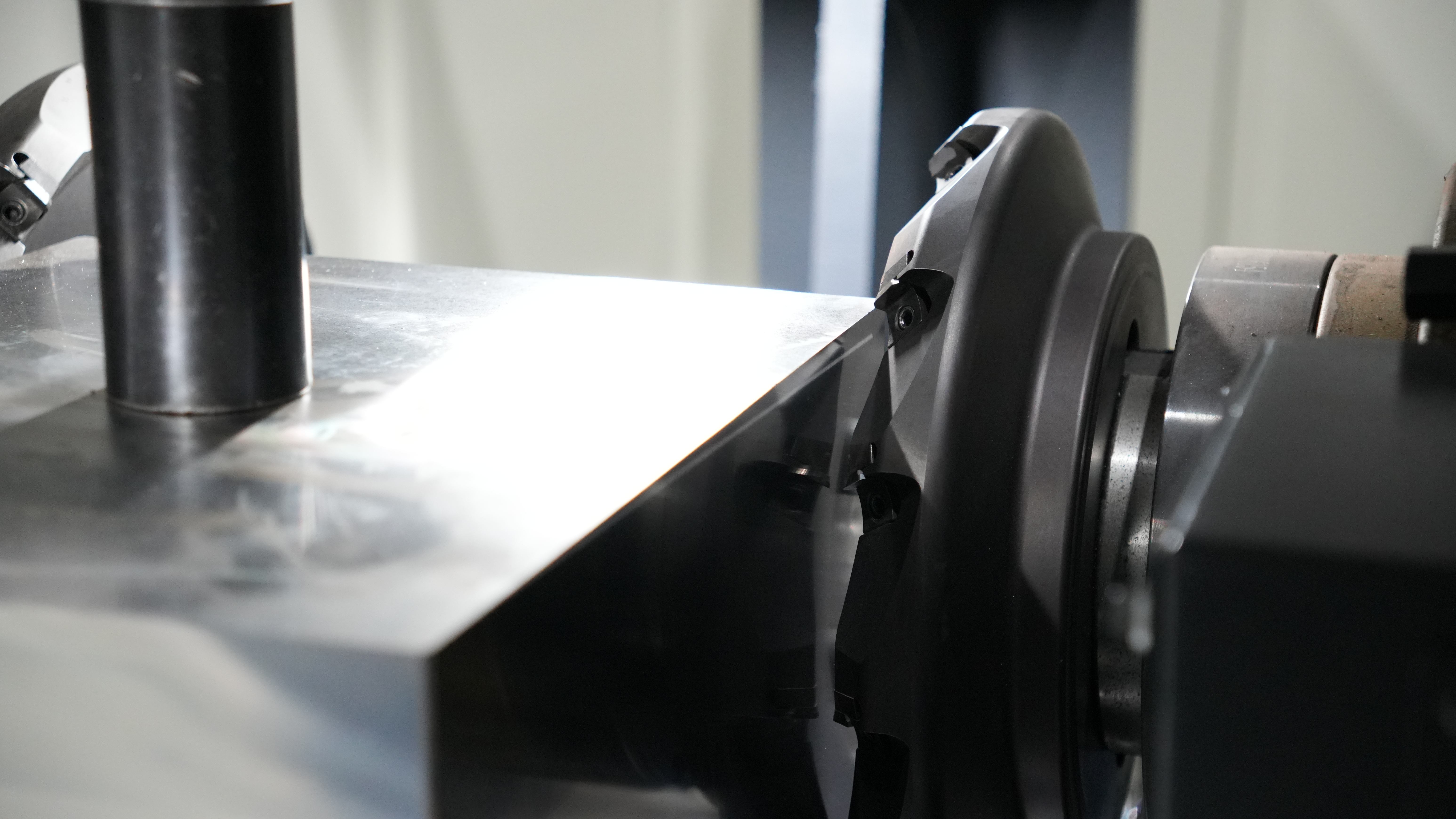
On a 12-ton one-piece cast-iron bed, the left and right spindles face each other with runout controlled within 0.003 mm. The hydraulic system locks the blank at the center, and two 250 mm carbide face mills cut inward simultaneously. The cutting forces on the left and right sides cancel each other out inside the workpiece.
That means:
· Fully balanced force on both sides
· Uniform temperature distribution during cutting
· No one-sided bending from directional force
· Even an 8 mm depth of cut on one side causes no distortion
The servo table beneath the base then rotates the workpiece smoothly by exactly 90.00 degrees. A Heidenhain linear scale monitors angular position, keeping indexing error within ±3 arc-seconds. Immediately after that, the two spindles advance again and finish the remaining two sides.
Because the workpiece stays clamped the entire time and the vise is never loosened, loading and unloading are reduced from four times to once. Cumulative error never gets a chance to build up. The finished six-sided block can be checked with a high-precision wide-base square, and no light will pass through the gap. Diagonal deviation remains steadily within 0.015 mm.
When machining P20 mold steel at HRC30, cutting resistance is especially high, and the tool bar on a single-head machine can easily deflect by 0.02 mm. On a twin-head machine, the opposed spindles are shorter and much more rigid, with only 150 mm of overhang. They remove the material decisively while still delivering an end-face finish as fine as Rz 3.2.
Materials like 6061-T6 aluminum alloy are much softer and more prone to thermal distortion. Removing 200 cm³ of aluminum chips per minute can drive local edge temperature up to 300°C. The twin-head machine’s through-coolant system blasts the tool tip at 70 bar, while the symmetrical skin removal releases internal residual stress evenly from both sides.
That brings several direct benefits:
· 70 bar high-pressure coolant removes heat quickly
· The cutting zone cools rapidly
· Symmetrical machining releases stress evenly
· The aluminum plate will not warp after machining
· The cut face does not yellow or burn
When these square, stable blanks reach the next operation, programming becomes much easier. The operator can simply probe one edge, set an absolute G54 zero point, and start the cycle. Previously, 1 mm of finish-machining stock had to be left as a safety margin; now that can be reduced confidently to 0.3 mm, cutting idle spindle travel by 40%.
Long parts are even more difficult to control dimensionally. On a 1,200 mm cast-iron guide rail, an included-angle error of just 0.03 degrees at the ends creates a 0.6 mm gap over the full length. The hydraulic clamps on the machine use floating adaptive clamping, with 8 cylinders automatically adjusting to the workpiece surface and holding pressure fixed at 15 MPa.
Temperature changes in the workshop also cause dimensions to drift. A rise from 15°C in the morning to 35°C in the afternoon can lengthen an ordinary screw by tens of microns. On the twin-head machine, the X and Y axes use hollow screws with 22°C constant-temperature cooling oil flowing inside, holding thermal deformation to within 5 microns. Parts made by day and night stay dimensionally identical.
The rotary table is also heavily engineered. It uses a curvic coupling with face gears, and once the table reaches position, 72 teeth above and below lock together hydraulically. With a clamping force of 3 tons, the table does not shift no matter how much the cutters vibrate, and the resulting cutter marks stay perfectly straight.
Even carbide inserts wear over time after 8 hours of continuous cutting. The machine’s laser tool setter can detect as little as 2 microns of tool shortening, and the control automatically applies independent compensation to the left and right spindles. The operator only needs to confirm the adjustment on the screen instead of reaching into the machine with a micrometer.
This means:
· 2-micron automatic tool compensation
· Non-contact laser detection
· No dependence on manual feel when measuring
· Near-zero scrap in batch production
At one factory producing 10,000 non-standard mold bases per month, more than half of all scrap used to come from the first reference corner being machined incorrectly. After switching to simultaneous twin-head machining, CMM inspection across 500 consecutive batches showed perpendicularity CPK values above 1.67, meeting aerospace-level no-inspection standards.
Solving Accuracy Drift
A 300 mm × 300 mm mold steel block often arches upward by 0.03 mm at the center immediately after the first pass on a single-side milling machine.
The reason is residual stress. Once one side is skinned off, the original internal force balance is destroyed. A twin-head machine solves this very directly: one 200 mm face mill on each side cuts at the same time. Each side removes 3 mm evenly, and the internal tensile and compressive forces are canceled out on the spot.
Loading no longer requires tapping the part into position by hand. A photoelectric sensor projects an infrared beam, and the probe finds the true center of the blank in just 0.5 seconds.
Once the coordinate system is established, both spindles travel from the origin by exactly the same distance. Even rough forged blanks with highly uneven surfaces can have an identical layer of black scale removed from both sides.
Clamping force itself is also a major source of dimensional loss. A conventional vise squeezes the workpiece laterally with a screw mechanism. When an operator slides an extension bar over the wrench and gives it half a turn, lateral clamping force can instantly exceed 3 tons.
Even an HRC40 steel block will bend by more than ten microns under that much side pressure. On a twin-head milling machine, lateral squeezing is replaced by vertical hydraulic down-force. Four cylinders press down evenly from above like a palm, while the hydraulic gauge holds steady at 8 MPa.
All four sides remain clear, and no matter how hard the cutter heads push inward, the part does not deform irregularly due to forced side loading.
That delivers three key benefits:
· Vertical hydraulic down-pressure replaces lateral squeezing
· The bottom reference surface stays fully seated on the support pads
· Clamping deformation is kept within 0.005 mm
Over the course of a morning’s work, each cutter can peel off 500 g of chips per minute, driving local tool-edge temperature above 400°C.
On a conventional single-spindle machine, as the spindle warms from a cold start in the morning to full temperature by noon, the spindle nose can extend forward by 0.02 to 0.05 mm purely due to thermal expansion, throwing off the machined size.
On the twin-head machine, the 15 kW spindle motor is enclosed in a constant-temperature water jacket. An industrial chiller pumps 18°C coolant through it at 30 L/min, locking the spindle housing temperature at around 25°C.
Deep heavy cutting also produces a huge volume of chips, and if those chips are not removed quickly, they become another source of heat. Piles of hot chips on the machine base can raise surrounding machine components by several degrees.
The twin-screw chip conveyor underneath removes 30 kg of hot chips per minute. Combined with water spray pipes flushing dead corners of the table at 15 bar, excess heat is sent immediately into the recycling bin.
The guideways beneath the bed are another major threat to accuracy. Every revolution of the cutter means each of the 6 carbide inserts strikes the material once, and all that high-frequency vibration has to be absorbed by the guide system.
The manufacturer uses heavy-duty size-65 roller linear guideways on the cast-iron base. Each slider is filled with cylindrical rollers and can withstand up to 8,200 kg of frontal and lateral impact force.
When vibration is prevented from propagating into the machine bed, the machined face comes out mirror-smooth. It feels perfectly flat to the touch, and a surface roughness tester can measure a stable Ra 1.6.
| Equipment Type | Clamping Method | Thermal Deformation Impact | Diagonal Error | Suitable Tolerance Grade |
| Old single-spindle machine | Heavy one-sided vise clamping (force biased to one side) | Prone to one-direction thermal bending | > 0.05 mm | IT8–IT9 |
| Twin-head opposed milling machine | Stable top hydraulic pressure (symmetrical force) | Cutting heat from both sides offsets each other | < 0.015 mm | IT6–IT7 |
After the left and right faces are finished, the table must rotate the part by 90 degrees to machine the remaining two sides. If the gears inside the rotary table have even a slight amount of play, say 0.01 degrees, a 600 mm long bar can end up with 0.1 mm of deviation at the far edge.
Once that part reaches the CNC machine for drilling, all hole locations will be off, and the entire batch may be scrapped.
Inside the twin-head milling table is a 144-tooth face gear disc. The instant indexing is complete, the upper and lower gear discs lock together precisely, holding repeat positioning accuracy within ±2 arc-seconds.
The two servo motors are not running independently either. A high-speed synchronization module on the system board instantly corrects even a 1 millisecond speed delay between the left and right cutter heads.
Matching spindle speeds prevents resonance. The finished part will not have one side smooth and the other side marked with inconsistent cutter lines.
Insert wear is another critical issue. After machining 200 pieces of 45 steel, the inserts on the right side may wear 0.005 mm more than those on the left, which immediately affects measured size.
That is why the laser tool-setting probe beside the machine stays active continuously. As soon as the beam scans the tool tip, the system captures a 5-micron shortening. On the very next cut, the right-side Z-axis automatically advances another 5 microns to compensate.
The entire sequence is completed automatically behind closed doors inside the machine enclosure. No one touches the workpiece, no sweat from human hands gets onto it, and there is no risk of someone misreading a micrometer scale.
After one full week of 24/7 operation, 1,500 standard cubes measuring 200 mm × 200 mm × 200 mm can be stacked on pallets. Quality inspectors can pull any piece at random, and the caliper reading will still fall steadily within a tolerance band of ±0.01 mm.