Choosing a double-head milling machine means matching the machine to workpiece size, output requirements, and automation level.
Common models typically handle blocks in the 120-1000 mm range, with rotary tables of 520-1000 mm, making them suitable for medium to large mold bases.
Dual spindles rated at 20-30 hp can machine two faces at the same time, improving efficiency by about 50% compared with a single-head machine, while still allowing one operator to run the machine.
For batch production, semi-automatic or PLC-controlled models with hydraulic automatic clamping, workpiece detection, and pallet-changing systems are recommended.
These features enable automatic positioning, three-stage clamping, and in-line inspection, cut clamping time by about 30%, and improve stability and continuous machining capability.
Block Size
Machining Range
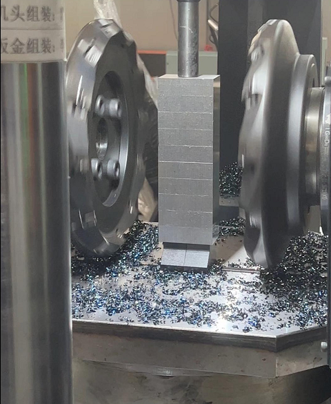
A block of P20 mold steel measuring 480 mm by 480 mm lands on the shop floor. The operator presses the start button, and the spindles on both sides, each fitted with a 160 mm cutter head, move toward the center.
As the cutter approaches the edge of the block, only 10 mm of tool run-out clearance remains. Coolant mixed with metal chips floods the area like molten iron, instantly clogging the chip evacuation channel. A machine rated for 500 mm may, in real production, only handle about 450 mm comfortably. Push it beyond that, and chips cannot clear properly. Insert temperature shoots up to 600°C, and the cutting edges blacken and burn within moments.
When selecting a machine, the maker’s nominal dimensions should be reduced by a 20% safety margin. If your daily job is machining 300 mm × 300 mm steel blocks, you should buy a machine in the 400 mm class. The cutter needs clearance at both the entry and exit ends of the blank, with at least 30-50 mm of extra space.
· 125 mm cutter head for a machine with 300 mm travel
· 160 mm cutter head for a machine with 500 mm travel
· 200 mm cutter head for a machine with 800 mm travel
· Run-out clearance should be calculated as the cutter radius plus 20 mm
· Coolant nozzles should be angled downward at 15°-25°
That gap allows a 70 bar coolant jet to flush chips cleanly off the inserts. When milling 5 mm off one side of No. 45 steel, the spindle load meter can jump straight to 85%. Without enough retreat distance, the motor starts and stops repeatedly, and the temperature inside the ball screw assembly quickly climbs above 45°C.
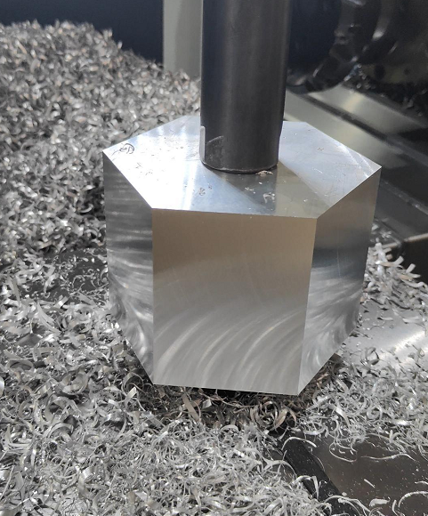
Now replace the steel block with a 7075 aluminum square only 22 mm thick. Hydraulic jaws with an 18 mm step height grip both sides tightly, leaving only 4 mm of exposed sidewall for machining.
Two cutter heads fitted with PCD inserts spin at 3000 rpm, skimming past the jaws. The operator watches nervously. The machine’s vertical positioning accuracy is rated at 0.005 mm. If even a 0.1 mm chip remains under the aluminum block, the high-speed cutter will shave a piece right off the steel jaw.
On the floor scale lies an 850 kg block of NAK80 pre-hardened steel, measuring 800 mm × 600 mm × 250 mm. The crane lifts the massive block unsteadily into place. The machine table is rated for 1500 kg, but the load concentration on the support pads increases several times over.
With that much weight on the table, the machine base undergoes micron-level deformation. The anchor bolts underneath must be retightened with a torque wrench to 250 N·m. When milling material at HRC40, two 15 kW motors operate at full load, and the guideways underneath must withstand several tons of thrust.
· Switch to heavy-duty roller guideways for workpieces over 500 kg
· Use an 11 kW or larger motor for materials above HRC35
· Increase cast-iron wall thickness in the base to 40 mm
· Install anchor bolts every 600 mm
With their large contact area, cylindrical rollers can hold 120 kN of static load without difficulty. Under an 850 kg block, slider deformation stays under 0.002 mm, and the milled surface remains flat.
Now consider a small brass cube measuring 30 mm × 30 mm × 30 mm and weighing only 220 g. Using a machine that weighs over ten tons to mill such a tiny part limits feed speed to about 10 m/min, and each part takes 3 minutes.
Switch to a smaller machine with 150 mm X-axis travel. Spindle speed rises to 6000 rpm, feed rate goes to 24 m/min, and hydraulic clamping is replaced by pneumatic clamps. Clamp action time drops from 1.2 seconds to 0.3 seconds. Each part now takes only 45 seconds.
Over a run of 10,000 parts, the difference adds up to 416 hours. A large machine uses 8 kWh per hour, so the electricity cost alone becomes significant. Small parts should go on small machines: equipment cost drops by 40%, and floor space is reduced to just 2.5 m².
· Air pressure set at 0.6 MPa and held for 0.3 seconds to clamp
· Cutting speed controlled at 400 m/min
· Chip load per tooth set to 0.15 mm
· Spindle changed to a lightweight BT30 interface
A block measuring 500 mm × 400 mm has a diagonal length of 640 mm. The enclosure space inside the machine must allow that 640 mm diagonal to rotate freely. When the table rotates the workpiece by 90° for the next face, the corners can easily hit the sheet-metal guard.
Machine & Size Matching
When buying a double-head milling machine, spindle specifications must match the size of the workpiece precisely. For small mold inserts with dimensions under 150 mm, a BT40 spindle is usually enough. A BT40 spindle typically delivers around 8000 N of drawbar force and can run at 1500 rpm during cutting. Pair it with a 7.5 kW spindle motor and an 80 mm cutter head.
Small parts do not require aggressive cutting. A machining allowance of 1.5 mm per side is enough. Set the hydraulic system pressure to 3 MPa, and the cylinder provides just enough clamping force to hold the block securely. Raise the pressure to 6 MPa, and a thin workpiece 150 mm long can bow upward by 0.03 mm in the middle.
For very small workpieces, the machine configuration needs to follow suit:
· Drawbar force kept at 8000 N
· Spindle speed starting at 1500 rpm
· Hydraulic pressure controlled within 3 MPa
· Depth of cut limited to 1.5 mm per side
For a standard mold plate measuring 300 mm × 300 mm, a BT40 spindle becomes underpowered. Increase the cutter diameter to 160 mm, and cutting resistance rises sharply. Upgrading the spindle taper to BT50 boosts drawbar force to 18,000 N. Without sufficient clamping force, a 160 mm cutter head can wobble by 0.02 mm under cutting vibration.
The spindle motor must also be upgraded, typically to 15 kW. Set the cutter depth to 4 mm, reduce spindle speed to 600 rpm, and rely on low-speed, high-torque cutting to bite into cast iron. The servo motor then pushes a worktable weighing several tons, while feed speed is kept below 120 mm/min.
Below is a commonly used parameter-matching chart for shop scheduling:
| Workpiece Length/Width | Spindle Interface | Motor Power | Cutter Diameter | Hydraulic Pressure | Depth per Side |
| 50-150 mm | BT40 | 5.5-7.5 kW | 80-100 mm | 2.5-3.5 MPa | 1-2 mm |
| 150-400 mm | BT50 | 11-15 kW | 125-160 mm | 4.0-6.0 MPa | 3-5 mm |
| 400-800 mm | Non-standard BT50 | 18.5-22 kW | 200-250 mm | 7.0-8.5 MPa | 6-8 mm |
When two large cutter heads machine a 400 mm-long workpiece at the same time, they can remove 2-3 kg of chips per minute. Chips fall like rain into the machine base. The chip conveyor underneath should have a chain plate width of at least 300 mm, and the motor should be upgraded to 0.4 kW just to drag the scrap out properly.
If the conveyor is too narrow, chips pile up into a mound and trap heat inside the machine. The cast-iron base under the spindle housing becomes too hot to touch. An infrared thermometer may show 55°C. At that temperature, the X-axis ball screw thermally expands by 0.015 mm, causing dimensional drift between the two ends of the workpiece.
Several hard requirements apply to chip evacuation and cooling:
· Chip conveyor chain width above 300 mm
· Conveyor motor at least 0.4 kW
· Coolant tank capacity above 400 L
· Pump flow rate at least 60 L/min
· Cutting zone temperature kept below 35°C
Shops typically keep a 400 L coolant tank on hand. The pump head should exceed 20 meters, with flow rate above 60 L/min. Two hoses with an inner diameter of 19 mm blast coolant directly at the cutter root, forcing the temperature in the tool-tip cutting zone below 35°C.
For oversized forgings such as 600 mm × 600 mm blocks with hardened skin, some machine builders supply custom spindles with dual-face flange contact. This adds an extra 2 mm annular contact surface on the flange face, doubling lateral load capacity compared with a standard BT50 interface.
A 22 kW heavy-cut spindle motor can deliver more than 300 N·m of torque. The cutter diameter grows to 250 mm, carrying 14 thick carbide inserts around its perimeter. Each insert is 6.35 mm thick, making it possible to peel off 8 mm of hardened skin in one pass.
The hydraulic pump should be sized to 15 L/min, with pressure raised to 8 MPa. Four heavy hydraulic cylinders, each 80 mm in diameter, clamp a forging weighing nearly 2 tons onto the table. Each clamp uses a 12 mm copper pad underneath to prevent slip and protect the workpiece surface.
For large heavy-duty machining, the following combinations are essential:
· Spindle with dual-face flange contact
· Motor torque above 300 N·m
· 12 mm copper pads under clamps
· Hydraulic cylinder diameter of 80 mm
· Indexing gear plate diameter above 500 mm
After two opposite faces are machined, the rotary table turns the workpiece in place. The hydraulic indexing gear plate underneath measures 500 mm in diameter and uses 72 interlocking teeth. Factory indexing accuracy is rated at ±3 arc-seconds.
Rotate the workpiece 90°, and the dimensional error on the opposite end of a 600 mm block stays within 0.01 mm. If the gear plate is too small or the teeth do not engage firmly enough, the corners will be machined out of square by several tenths of a degree after rotation.
Installing a 20-ton machine requires a serious foundation. The floor must be excavated to a depth of 2 meters, then filled with 400 mm of C50 reinforced concrete with 22 mm rebar mesh. Under heavy cutting, the dial indicator beside the machine should remain completely steady.
The standard distance from spindle face to table center is 350 mm. For thick plates over 300 mm, that is not enough. When ordering the machine, the contract should specify moving the spindle column back to extend that center distance to 450 mm.

Thickness Limits
The machine catalog may list a maximum clamping thickness of 400 mm. Then a 380 mm-thick block of P20 mold steel arrives, suspended from the crane and lowered between the jaws.
The hydraulic jaws open only to 390 mm at full extension. The block surface still carries 5 mm of scale and raised irregularities, so it jams halfway in. In real use, the theoretical opening should exceed blank thickness by at least 30 mm, giving the crane operator enough room to align the workpiece.
For blanks thicker than 350 mm, the protective doors on both sides of the machine should open in a split-door configuration. A single door often interferes within a 700 mm stroke and can be dented when a thick plate swings during lifting.
Running at thickness limits creates one set of problems. Running very thin stock creates another. A batch of S136 corrosion-resistant mirror-finish steel plates arrives, each only 25 mm thick. The standard jaw step height is 20 mm, leaving just 5 mm of the plate exposed above the jaws.
Two 160 mm cutter heads spinning at 800 rpm move in. The inserts shave off 3 mm of material, while the lower edge of the cutter is now just 2 mm above the hardened steel jaw. The operator barely dares blink. If even a 0.5 mm chip gets trapped underneath, dozens of carbide inserts can shatter instantly.
For thin-plate machining, these factory parameters must be checked carefully:
· Standard jaw step height is usually 18-22 mm
· Keep 5 mm of safe Z-axis tool clearance
· Probe sensing distance set to 2 mm above the jaws
· Tool wear compensation limit held within 0.2 mm
A batch of aluminum plates only 15 mm thick arrives. The operator leaves hydraulic pressure at the standard 5 MPa, and the cylinders push the jaws hard into both sides. The 400 mm × 400 mm plate silently bows upward by 0.08 mm in the center under compression.
The cutter heads flatten the bowed section completely during machining. The finished surface looks mirror-bright, and an optical flatness check appears perfect. But once the clamps release, the side pressure is gone. The 15 mm plate springs back, leaving the center permanently warped like a bow.
Metal plates thinner than 25 mm subjected to more than 3 tons of hydraulic force from one side can develop 0.05-0.1 mm of permanent bending deformation as internal stress is released.
Thin plates should not rely on brute-force hydraulic clamping alone. Machine builders often develop special step-jaw designs for this purpose. The clamping face height is reduced to 8 mm, while a 12 mm support step is added underneath. The 8 mm grip point holds the lower half of a 15 mm aluminum plate securely.
The hydraulic station is also fitted with a proportional pressure-reducing valve. The operator reaches into the electrical cabinet and turns clamping pressure down from 5 MPa to 1.5 MPa. The plate no longer bows. But with only 1.5 MPa of force, the cutter depth must be reduced from 3 mm to 0.5 mm, requiring multiple light passes.
An electro-permanent magnetic chuck measuring 600 mm × 600 mm × 80 mm is installed on the table. A 0.2-second electrical pulse reverses the polarity of the neodymium magnets inside.
Several hard requirements apply to electro-permanent chucks:
· Magnetic force of 16 kg/cm²
· Magnetize/demagnetize time within 0.5 seconds
· Pole pitch set to 50 × 50 mm
· Chuck surface ground to 0.005 mm flatness
· Permanent holding force maintained even during power loss
A 15 mm low-carbon steel plate lies flat on the chuck. At 16 kg/cm², the vertical magnetic pull holds it firmly in place. With no jaws blocking the sides, both cutter heads can move freely. Z-axis mechanical interference disappears completely, and the inserts can cut to within 1 mm of the chuck surface.
A square plate with 500 mm side length sits on hundreds of magnetic pole blocks. Total downward holding force reaches nearly 40 tons. Even with both 15 kW spindle motors running at full load and each cutter peeling off 5 mm of steel, the plate does not shift by 0.01 mm.
For non-magnetic materials such as copper, aluminum, or stainless steel, the magnetic chuck is useless. Shops therefore keep precision shims with thickness tolerances within 0.002 mm. Two shims measuring 20 mm wide and 10 mm high are placed under the standard step jaws.
Output
Loading/Unloading & Cutting
A double-head milling machine with 250 mm face mills is machining an 800 mm-long block of No. 45 steel. The spindles run at 800 rpm, and the feed moves through 750 mm. The cutting sounds crisp, and the machining pass finishes in just over 3.5 minutes.
The operator presses spindle stop and opens the safety door. Removing the 120 kg steel blank is another story. The shop crane is being used at the next station, so the operator waits 7 minutes. Once the hook arrives, lifting rings are attached, four M24 clamp bolts are loosened with a wrench, the clamps are pulled back, and the block is lifted away slowly.
The table is covered with chips soaked in coolant. The operator uses a high-pressure air gun and brush to clean the 500 mm fixture base. Even a few 0.5 mm chips left behind can throw the parallelism of the next blank out by 0.03 mm. Cleaning, reloading, and re-indicating the next part take the stopwatch to 18 minutes.
Manual loading involves several time-consuming steps:
· Waiting for crane availability: 3-8 minutes each cycle
· Cleaning locating surfaces: 2 minutes each cycle
· Tightening and loosening clamps with a wrench: 3 minutes each cycle
· Dial-indicator alignment and tapping: 4-5 minutes each cycle
Set hydraulic pressure to 7 MPa and place the workpiece in a V-jaw fixture. Press the foot switch, and the hydraulic cylinder locks it in place within 2 seconds. What used to be an 18-minute loading/unloading process is reduced to under 3 minutes.
When the 16 carbide inserts on the face mill wear out, they must be indexed manually. The operator loosens each insert screw with a hex wrench, rotates the insert, and then uses a 50 mm tool-setting block to touch off the cutter by hand. Compensating Z-axis length on both sides takes 10 minutes.
Now consider an automatic tool measuring system. The cutter spins through a laser beam at 1500 rpm. As soon as the beam is interrupted between emitter and receiver, the CNC system writes the actual rotating diameter and tool length into the compensation register in just 8 seconds.
With a 5 mm depth of cut per side, both cutter heads can remove 2000 cm³ of metal chips per minute. Chips fall like a storm into the base, while the coolant pump sprays 60 L/min onto the inside of the guard enclosure.
Poor chip evacuation forces production stoppages:
· Clearing a jammed chain conveyor: 15 minutes each time
· Cleaning the coolant tank filter: 10 minutes each time
· Manually removing tangled chips from the cutter head: 3 minutes each time
A machine with an X-axis rapid traverse of 15 m/min needs 5 seconds to travel 1200 mm. Returning the table to the loading position and moving back to the cutting start point takes 10 seconds in total. Increase motor power and raise rapid traverse to 48 m/min, and the same motion drops to 1.5 seconds.
To avoid crashing the cutter into irregular blank edges, programmers often leave a 50 mm safety distance. At a feed rate of 500 mm/min, the cutter spends 6 seconds moving through air before it even touches metal. A contour-scanning probe system can reduce that safety distance to just 5 mm.
At 8:00 a.m., when the operator is still fresh and moving quickly, part-to-part cycle time is about 22 minutes. By 3:00 p.m., after handling more than a dozen heavy workpieces, the operator’s arms are sore. Cleaning inside the machine slows down, bolt tightening becomes less consistent, and cycle time stretches quietly to 29 minutes.
MRR & Machine Rigidity
A P20 mold steel block measuring 400 mm × 400 mm × 400 mm is mounted on the table of a double-head milling machine. Each end spindle carries a heavy-duty roughing cutter head weighing 15 kg and measuring 250 mm in diameter. The spindle motors are rated at 22 kW and drive through a two-stage gearbox. In low gear, the tachometer settles at 450 rpm.
The instant the inserts bite into the steel, spindle load jumps to 85%. Depth of cut is set to 6 mm per side, and feed per tooth reaches 0.25 mm. The shop fills with a deep cutting roar.
In a single minute, the two cutter heads strip away more than 2800 cm³ of metal. The chips are about 1.2 mm thick and dark blue from heat.
To suppress vibration at that level, a lightweight machine frame is not enough. The bed is made of FC300 Meehanite high-strength cast iron, with a single casting weight above 8 tons. The X-axis guideways span 1500 mm, each rail is 160 mm wide, and the distance between the two rails is widened to 850 mm, giving the machine a broad and stable stance.
The cast-iron guide surfaces are induction-hardened to above HRC50. The sliding surface under the table is lined with 2 mm PTFE wear strips. During assembly, workers scrape 12-14 microscopic contact points per square inch by hand. Oil film forms hydrostatic support in those pockets, carrying a 3-ton blank without distortion.
The spindle nose uses a BT50 interface with a large taper. The drawbar claws grip the pull stud with 1800 kg of force. Inside the headstock is a gear train forged from chromium-molybdenum alloy steel. Unlike belt drives, which can slip under heavy load, wide-face mechanical gears transmit cutting torque steadily up to 1200 N·m.
Now switch to machining 7075 aerospace-grade aluminum. The heavy gearbox becomes a disadvantage. Maximum spindle speed is only 4000 rpm, cutting speed is too low, and soft aluminum chips stick to the tool edge instead of flying off. Aluminum-cutting machines therefore use an 18 kW direct-drive spindle with no gearbox, where the motor rotor is coupled directly to the spindle shaft. Speed rises easily above 12,000 rpm.
Feed rate for aluminum is raised to 8000 mm/min. But the friction of cast-iron box ways becomes a bottleneck, and the servo struggles to follow command positions. The X-axis is then upgraded to 45-size P4 roller linear guideways. Four rows of cylindrical rollers circulate inside the block, reducing friction coefficient to 0.002. The table, carrying a 200 kg aluminum part, can now rapid-traverse at 36 m/min.
The cutter for steel uses 12 coated carbide inserts with a slight negative land for impact resistance. The cutter for aluminum uses only 3 PCD inserts. Its sharp, high-rake geometry produces light, snow-like chips even at 3 mm depth of cut per side.
Compare the manuals of two differently configured double-head milling machines, and the design priorities become clear:
| Parameter | Heavy-Duty Configuration | High-Speed Configuration |
| Spindle drive | Two-speed gearbox | Direct-drive motor |
| Maximum output torque | 1200 N·m | 150 N·m |
| X/Y guideway type | 160 mm wide hardened box ways | 45-size roller linear guides |
| Cast-iron base weight | 8500 kg | 4200 kg |
| Maximum rapid traverse | 10 m/min | 36 m/min |
Now load a 2-ton HT250 cast-iron base onto the high-speed machine. Cut at 0.15 mm feed per tooth, and spindle load instantly hits 120%. A sharp, penetrating scream fills the shop. The inserts bounce repeatedly on the metal, leaving washboard chatter marks up to 0.05 mm deep on the machined surface.
Under that vibration, carbide insert life drops from the normal 180 minutes to just 40 minutes. A box of ten inserts costs RMB 600, and an 8-hour shift may consume three extra boxes. Under abnormal radial shock, spindle bearing life also collapses. Replacing the four-row cylindrical roller bearings at the spindle nose can cost RMB 20,000.
Material removal rate is determined by spindle speed, feed rate, and depth of cut. A heavy machine, backed by a massive base, can remove 2800 cm³ of steel per minute and still maintain surface roughness of Ra3.2. A lighter machine cutting the same hard material must reduce depth of cut to 1 mm per side to avoid chatter and can only remove 400 cm³ per minute.
Order Mix
The first three job sheets call for machining five cold-work tool steel blocks 150 mm wide. The next order immediately switches to eight cast-iron spacer blocks 450 mm wide.
The operator grabs a size-36 wrench and walks to both sides of the machine. After loosening eight M24 bolts locking the spindle slides, he turns the handwheel again and again, forcing the spindle head—tens of kilograms in weight—back from the 150 mm position to the 450 mm mark. The whole adjustment takes 25 minutes.
In shops that handle dozens of mixed small orders every day, operators can spend half their time cranking handwheels and resetting fixtures while the spindle stands still and not a gram of metal is cut.
In an upgraded setup, each spindle slide runs on a 40 mm diameter C3 ball screw with 10 mm lead. Press one button on the control panel, and two 3 kW servo motors move the slides simultaneously. Opening the spacing from 150 mm to 450 mm now takes only 12 seconds.
Mixed-order machining also demands high fixture flexibility:
· Hydraulic self-centering vises should cover an opening range of 50-600 mm
· Spacer block changeover time should be kept within 1 minute
· Jaw inserts should use HRC58 carbide with a mesh anti-slip pattern
In a high-mix shop, batch size often ranges from 3 to 10 parts. Actual cutting time is only 5-6 minutes, while changeover takes 30 minutes. If changeovers exceed 8 times per day, the machine can lose 4 hours just in setup. A machine with fast-change capability can recover 3 hours of productive time in a single day.
Now picture a pallet loaded with 2000 identical steel blocks measuring 250 mm × 250 mm. For three straight months, the machine does not need any width adjustment at all. The operator’s job becomes repetitive: load, press start, unload, blow off chips.
If a machine runs continuously for three months, a single breakdown in the middle of the night that takes 4 hours to troubleshoot and repair can wipe out several hundred parts of output, forcing the whole shop into extra night shifts to catch up.
For high-output work, mean time between failures becomes the top priority in machine selection. The disc springs inside the spindle must withstand over 2 million tool clamp/unclamp cycles without cracking. The centralized lubrication pump tank should be increased to 10 L, delivering 2 mL of oil to each guideway and screw every 45 minutes. Sheet-metal dust cover joints should be increased to 2.5 mm thick to withstand constant coolant flow of 60 L/min.
To squeeze out every second of productivity, a two-station APC system is introduced. The worktable is split into two halves linked by a hydraulic rotary shaft. Inside the enclosure, the cutter heads are machining a 30 kg steel plate at 800 rpm. Outside, the operator calmly lifts the next blank with a crane and clamps it onto the outer pallet.
When machining time reaches zero, the guard door slides open automatically. The pallet lifts, rotates 180°, drops, and locks. The entire exchange takes 16 seconds. The fresh blank is now in the cutting chamber, and the finished part is outside. The spindle no longer waits for slow manual loading. Actual daily spindle runtime increases from 5 hours to 7.5 hours.
A robot can take automation further. A six-axis arm with 50 kg payload is installed directly in front of the machine. Beside it, a storage rack holds 500 blanks ready for machining. The robot reaches in with a pneumatic gripper, grabs a 15 kg block, loads it into the fixture, and retreats—all in 18 seconds.
For the robot and machine to work together, the base-level signals must be integrated:
· Fixture pressure switch confirms 7 MPa hydraulic clamping is reached
· Spindle air-blow system confirms no chips remain on the locating surface
· In-machine anti-collision probe confirms blank stock allowance stays within 5 mm tolerance
If one insert on a 200 mm cutter head chips, the machine may continue cutting blindly. The resulting imbalance can scrap the next part or even destroy spindle bearings. A spindle motor load-monitoring module solves this by detecting a sudden 20% abnormal load rise within 0.1 second, immediately cutting feed and stopping the machine with an alarm.
Automation Needs
One-Off and Small Batch
The first drawing calls for a block of P20 mold steel 500 mm long and 300 mm wide. It takes two hours to machine, then the machine stops for unloading. By 9:30 a.m., the next job is an aluminum plate only 45 mm thick. All day long, the spindle starts and stops. More than 3.5 hours per day are lost just waiting for operators to load and clamp workpieces.
Around the control panel are stacks of spacer blocks and clamp plates in all kinds of sizes. When a 750 kg cast-iron part arrives, even an operator with five years of experience must use a 5-ton crane carefully and measure diagonals repeatedly with calipers.
The spindle, fitted with an edge finder, inches toward the blank. The instant it touches the edge, the tool emits a harsh beep. Spindle speed must be held steady at 500 rpm, and the operator proceeds slowly. Just locating the machining position on one heavy block can take 25 minutes.
Now use a probe instead. The probe moves toward the workpiece at 2000 mm/min. As soon as the ruby stylus touches the steel plate, it sends an electrical signal back to the Siemens 840D control. The entire 3D coordinate system is established in under 45 seconds.
· Repeatability error under 0.001 mm
· The system can generate tool compensation directly from drawing tolerances
· Infrared signal transmission is unaffected by flying chips
· The internal trigger spring can withstand 2 million actuations
The old clamping method with step blocks and top clamps is replaced by a pneumatic self-centering vise. Shop air pressure is set to 0.6 MPa. The jaws open to 350 mm, enough for a medium-sized mold blank. The operator steps on the pedal, and the cylinder snaps the jaws shut.
As the jaws move inward, they generate 40 kN of clamping force. Previously, when a 60 mm thin plate was clamped with conventional top clamps, the middle could bow by 0.15 mm. The new vise includes a 45° downward pull angle. Carbide teeth grip the blank firmly, and after removing 3 mm of stock, flatness error stays below 0.02 mm.
In job-shop production, dozens of tools may be changed every day, and operators constantly enter tool data manually. A 160 mm face mill with 10 inserts requires tool length and radius values to be keyed in by hand. One misplaced decimal point can crash the machine. A BT50 spindle overhaul can cost RMB 45,000, not including two weeks of downtime.
Outside the machine, a tool-setting station kept at 22°C uses RFID-based tool identification. A laser beam scans the tool and measures it accurately. Tool length 185.35 mm and radius 79.98 mm are written into the microchip embedded in the toolholder. The chain-type tool magazine then loads the tool automatically whenever needed.
· The chip can store 256 bytes of data
· Remaining tool life can be tracked in real time
· The system can automatically limit maximum spindle speed for each tool
· It can trigger alarms before the tool breaks on a hard spot
When 20 completely different urgent drawings arrive in one day, operators no longer need to flip through grease-stained A4 sheets. They scan the barcode on the routing card with a handheld reader. The double-head milling machine then pulls the correct G-code from the shop server. The program already contains fixed parameters such as 0.8 mm per revolution for roughing and 0.1 mm depth for finishing.
In heavy block cutting, curled chips quickly pile into a mountain beneath the table. The machine is fitted with dual auger chip conveyors. Two screw conveyors rotate continuously at 1.5 m/min to push chips out. A high-power pump delivers center-through coolant at 20 kg pressure, blasting the hot cutter heads relentlessly.
Red-hot chips fresh off the cut, at nearly 500°C, slide down the stainless steel deflector into the trench conveyor below and are carried to the scrap area. The owner’s monthly production report tells the story clearly: a conventional single-spindle milling machine with full manual loading and tool setting spends only 4.2 hours of an 8-hour day actually cutting metal.
Add a semi-automatic double-head milling machine with in-machine probing and foot-pedal pneumatic clamping, and actual cutting time extends to 6.8 hours per shift. The machine can produce five more No. 45 carbon steel template plates 80 mm thick per day. Local subcontract shops charge RMB 150 per part.
That means RMB 750 more revenue in a single daytime shift. Over 280 working days per year, the additional revenue reaches RMB 210,000. The imported probe and pneumatic vise cost only RMB 65,000.
Medium Batch
Now the order changes to 200 pieces of 718H pre-hardened plastic mold steel. Every block measures 400 mm × 400 mm × 150 mm, and each one weighs 188 kg. The drawing requires all six faces to be finish-machined to Ra1.6.
To flip a 188 kg block manually, the operator loops a nylon sling under it, hooks it to the crane, lifts it slowly, then pushes it by hand while it hangs to rotate it 90° before setting it back down.
Just brushing chips off the table and hammering the part flat again can consume 8 minutes per flip. Across 200 parts, downtime from manual flipping alone exceeds 26 hours.
A hydraulic CNC indexing table is installed in the center of the double-head milling machine. As soon as the two spindle heads finish removing 3 mm of material at 1200 mm/min, the cutters retract 200 mm to a safe distance, and the indexing table raises the steel block by 5 mm.
The hydraulic motor then takes over. The 188 kg block rotates smoothly 90° in 12 seconds. The table drops back down, and the internal drawbar instantly generates 50 kN of locking force. The two cutter heads move in again and continue machining the next two faces.
| Process Data Comparison | Manual Crane Flipping | CNC Indexing Table | Difference |
| Flip time per part | 8 min 30 sec | 12 sec | 97% reduction |
| Output per shift | 18 pcs | 31 pcs | 72% increase |
| Perpendicularity error across four faces | 0.05 mm | 0.015 mm | Higher accuracy |
| Operator walking steps per shift | 14,500 | 3,200 | Dramatically lower physical strain |
A machine priced at over RMB 1 million sitting idle for 3 hours a day is painful to watch, especially while the owner is still paying RMB 35,000 a month in equipment financing.
That is where a dual-pallet exchange system (APC) comes in. Pallet A enters the fully enclosed sheet-metal housing and runs a 25-minute machining cycle. Outside the machine, the operator uses a jib crane to mount the next blank onto pallet B.
When pallet A finishes, the pneumatic safety door lifts upward. A servo motor drives two heavy chains underneath. Pallet A, covered in chips, slides out, while pallet B, already loaded and clamped, slides in along four linear guide rails. The entire exchange takes 18 seconds.
Continuous machining of 200 pieces of 718H produces blue chips piled like a hill. With material hardness at HRC32, the cutting point temperature rises instantly to 600°C. The coolant tank is therefore enlarged to 450 L, and two high-pressure hoses blast emulsion directly at the tool tip.
In medium-batch work, unnoticed insert wear is a major risk. The CNC control sets a 45-minute tool life for the 80 mm milling cutter. When the countdown ends, the automatic arm pulls a fresh cutter from the 40-tool carousel and loads it into the spindle.
In the old setup, the operator would soak through two shirts per shift and walk more than 10,000 steps around the machine. Now four workpieces can be prepared in an hour, and the rest of the time the operator sits by a fan and monitors the screen.
The contract price for this batch of 200 parts is RMB 450 per piece, for a total of RMB 90,000. Previously, with labor-intensive round-the-clock operation, delivery took 8 days. Now the machine runs 24 hours a day and finishes in just 3.5 days. With fewer night shifts, the shop even saves 400 kWh by switching off some lighting.
High Volume
The first delivery quantity is fixed at 50,000 pieces. The die-cast aluminum blanks all measure 800 mm × 600 mm × 40 mm. The buyer has forced cycle time down to just 280 seconds per part.
Manual production simply cannot handle that volume. Even with three shifts running around the clock, the shop would need 12 skilled operators dedicated to the machine. A recruitment sign hung at the factory gate for two weeks, offering a basic wage of RMB 9,500 per month, attracted only two recent graduates. Forklifts move dozens of pallets of die-cast aluminum parts across the shop floor every day.
The highest scrap risk comes around 3:00 a.m. on the night shift. One drowsy operator forgets to tighten a single bolt, and at 8000 rpm the aluminum plate flies out and punches through the sheet-metal enclosure. The loss from one scrapped part plus machine repair can reach RMB 12,000.
So the machine is redesigned for automation. Four 1.2-meter-deep concrete anchor pits are poured beside the double-head milling machine. A FANUC M-710iC six-axis industrial robot is fixed on a base. Its maximum reach is 3.1 meters, and its payload is 70 kg.
An AGV follows magnetic guide lines on the floor and stops in the loading zone on the robot’s left, carrying 48 blanks at a time. The robot’s quick-change pneumatic gripper presses down, and four vacuum cups firmly pick up a 25 kg aluminum base.
· The robot completes a 180° turn from cart to machine within 5 seconds
· An air nozzle blows off the locating surface with 0.8 MPa compressed air
· Four zero-point locating studs snap into place with a sharp metallic click
· The spindle starts only after receiving the robot’s “ready” signal
Two 125 mm PCD disc cutters scream into the aluminum at 20,000 rpm. The 5 mm machining allowance on each side turns into a cloud of silver chips in just 12 seconds. An in-machine camera streams live video to a 65-inch screen in the supervisor’s office.
In a 50,000-piece order, a damaged insert can quietly ruin output for hours. The system therefore enables real-time spindle load monitoring. During normal cutting, spindle current draws a steady line at 25 A. If the tool hits a hard spot or the insert wears down, the current jumps past the 35 A warning line. The CNC immediately slows the spindle and retracts the tool.
If just one insert chips on the cutter, the next 80 battery bases may all fail surface-finish requirements. The tool life management module therefore forces a tool change after 120 minutes of cutting.
The line generates 4 tons of aluminum chips every day. Dual auger conveyors are no longer enough for that volume. A wide belt conveyor is installed in the trench, carrying chips out at 4 m/min to a briquetting press outside the workshop.
The scrap aluminum is compressed into solid blocks only one-tenth of its original volume. A 10-ton recycling truck comes every three days to haul them away. Revenue from the aluminum briquettes is enough to offset the machine’s entire monthly electricity bill. Inside the machine are 120 tools, and the automatic storage system holds enough blanks for 72 hours of continuous unattended production.