A horizontal machining center uses a horizontally oriented spindle and is built specifically for large mold base machining.
With gravity assisting chip evacuation, it can handle heavy cutting with depths greater than 10 mm in a stable, repeatable way.
Paired with a B-axis rotary table, it can mill and drill all four sides of a part in a single setup, cutting setup changes by 75%, dramatically improving efficiency while eliminating the positioning errors that come with repeated re-clamping.
What Exactly is an HMC
The machine is equipped with a B-axis indexing table with indexing accuracy as high as 0.001°.
It comes standard with a dual automatic pallet changer (APC), allowing milling and boring on all four sides of a workpiece in a single setup.
When machining a 400 mm × 400 mm cast-iron gearbox housing, an HMC uses gravity to let chips fall away naturally, achieving a chip evacuation rate of over 95%.
The spindle does not recut chips, so actual tool-in-cut time rises to more than 80%.
The machine is typically fitted with a high-power 30 kW to 50 kW spindle motor that delivers the torque required for heavy-duty cutting.
Horizontal Spindle Layout
The operator stands on the anti-slip footboard at the load station, holding a torque wrench preset to 80 N·m. Four carbide clamps lock a 300 mm × 300 mm × 200 mm aluminum alloy valve body blank onto a 400 mm square pallet. The entire loading process is completed within three minutes.
He steps on the foot switch beneath the machine enclosure. The 500 kg protective doors slide open to both sides. The hydraulic lift arm of the automatic pallet changer (APC) rises 50 mm. Following a 180-degree semicircular path, the mechanism swaps the finished pallet inside the machine with the new pallet loaded with raw blanks outside. The physical exchange takes only 9.5 seconds.
The new pallet slides into the machining area rails. The pull-down clamping system releases 40,000 N of holding force. The pallet base is locked rigidly onto the high-precision B-axis indexing table. The B-axis servo motor drives the rotary mechanism, and the table stops at any of 360,000 discrete programmed positions, with a single-rotation positioning error of no more than 0.001°.
· Drill four 8.5 mm blind holes on the front face of the part
· Rotate the fixture 90° and mill a 150 mm-long flange surface on the side
· Rotate another 90° and bore a bearing counterbore on the back face to a 0.005 mm tolerance
· Stop the fixture at 45° to machine an angled hydraulic oil passage
On a vertical mill, the operator would normally flip the part by hand three separate times to machine those four faces. Each time, the hydraulic vise must be loosened, chips blown away with high-pressure air, and the blank re-indicated with a dial gauge. That manual routine consumes an average of 15 minutes each time. Repeated re-clamping across four faces adds up to 45 minutes of machine downtime.
Each manual handling step introduces tiny geometric deviations. A flatness error of 0.01 mm from the first setup can be mechanically amplified during the second re-indicating operation after flipping the part. By the time the intersecting hole coordinates on the fourth face are checked, the coaxiality has drifted 0.03 mm outside the drawing tolerance.
A pallet fitted with a four-sided tombstone fixture eliminates all of those repeated flip-and-reclamp steps. The part stays locked to the fixture while the B-axis rotates it under program control. Linear positioning on the X, Y, and Z axes is kept within a strict 0.002 mm micron-level range by closed-loop glass scales.
A hydraulic valve block manufacturer in Texas recorded the loading parameters in its job documentation. A cast-iron tombstone fixture 800 mm high was loaded with 16 high-density flat vises across its four faces. At the external load station, the operator mounted 16 pieces of G3000 gray cast iron stock in one go.
· A fully loaded 500 mm pallet weighs more than 800 kg in total
· The center spacing of the four stations on each face is arranged precisely at 120 mm
· The pneumatic supply pressure is maintained at 0.6 MPa to prevent parts from loosening
· The airtightness detection sensor responds in as little as 2 milliseconds
The chain-type automatic tool changer (ATC) mounted on the machine side is packed with cutting tools. The chain carries 120 milling cutters and boring tools of different lengths and flute counts. In 1.5 seconds, the tool-change arm inserts a 12 mm solid carbide drill into the spindle taper. The same size compensation values on that single drill are used to machine all 64 faces across the 16 valve blocks.
With the impact-resistant glass door closed, the machine cuts continuously through all 16 cast-iron blanks. The countdown timer on the control panel shows a total program time of 4.5 hours. During that time, the operator leaves the machine and walks to the adjacent assembly area, where he spends two hours bolting together a batch of heavy flanges with 600 mm outside diameters using high-strength bolts.
The dual-pallet system on a single machine can also be integrated into a flexible manufacturing system (FMS). At an industrial gearbox plant in Nagoya, Japan, a 30-meter rail line was installed across the shop floor. Heavy steel rails connect 12 identical HMCs in a row. On both sides of the track, three-level pallet racks hold 60 standard metal pallets in standby.
The scheduling computer in the control room reads the RFID chip mounted on the underside of each pallet. The 128 KB chip stores whether the material is a tractor transmission center case or a cast-iron rear cover. A rail-guided vehicle (RGV) travels at 80 meters per minute, delivering loaded pallets into any open machining station.
· The laser anti-collision radar is set to a physical detection range of 3.5 meters
· The shuttle’s repeat mechanical positioning error is calibrated to 0.05 mm
· The high-pressure wash station sprays at 50 bar
· The pneumatic lift table at the load station has a maximum load capacity of 1,500 kg
The spindle calls up No. 45, a large-diameter face mill, according to the G-code sent over the network. No one needs to use a dial indicator to re-establish the XYZ work zero. The coordinate offsets from G54 to G59 are already stored in the database for the locating pins at the base of the fixture.
The production figures on the line report sit on the shop supervisor’s desk. Over an 8-hour day shift, three three-axis vertical machines and three operators produce 45 qualified metal parts. A single HMC with an external pallet pool, monitored by just one inspector, turns out 110 finished components with a surface roughness of Ra 0.8. The scrap rate on the quality report drops from 1.5% to below 0.1%.
Tombstone Fixture
The operator secures a 600 mm-high cast-iron tombstone with four M20 high-strength bolts onto the HMC’s 500 mm rotary pallet. The four vertical faces are densely covered with threaded blind holes. M16 threaded holes are arranged in a precise 12-by-8 grid at 50 mm intervals.
The tombstone is made from FC300 gray cast iron. Its hollow internal structure has a wall thickness of 45 mm. After casting, it is left outdoors for a full six months to relieve residual internal crystal stress. All four faces are then machined on a large gantry surface grinder. Over a length of 500 mm, the maximum flatness error does not exceed 0.01 mm.
The perpendicularity tolerance between adjacent faces is tightly controlled within 0.015 mm. On the first face, the operator locks down four hydraulic vises. Each vise grips a 150 mm × 100 mm × 50 mm blank of 7075-T6 aerospace-grade aluminum.
An external hydraulic power unit continuously supplies fluid pressure to keep the system running.
· The hydraulic oil tank has a full capacity of 80 liters
· The suction filter is rated at 10 microns
· The gear pump motor is rated at 2.2 kW
High-pressure oil travels through 8 mm internal oil passages inside the tombstone and is distributed to the hydraulic cylinders of all 16 vises. The clamping force of each individual piston remains stable at 3,500 N. A total of 16 identical aluminum blocks are fixed across the four faces.
The B-axis servo motor rotates the pallet to the commanded angular position, where it stops and locks. The spindle calls up a 12 mm solid carbide end mill from the tool changer. At 8,000 RPM, the cutter bites into the four parts on the first face. The depth of cut remains at 6 mm, and the feed rate reaches 2,400 mm/min.
Once rough contour milling is completed on the first four parts, the pallet releases its internal hydraulic brake and rotates 90°. The same end mill continues machining the four blanks on the second face using the same cutting parameters. The tool never has to return to the chain magazine. All 16 parts are rough-machined in a single run with the same cutter.
By reducing non-cutting tool travel, the machine saves valuable cycle time. Rough machining all 16 parts cuts nearly five minutes of spindle waiting time. The single-part cycle time on the production control report keeps falling.
| Tombstone Fixture Style | Material Density (g/cm³) | Applicable Pallet Size | Maximum Workpiece Capacity When Fully Loaded (estimated with 50 mm parts) | Empty Weight |
| Standard Four-Sided Cross Type | 7.3 (gray cast iron) | 400 mm × 400 mm | 32 pieces | 185 kg |
| A-Frame Dual-Face Angled Type | 7.3 (gray cast iron) | 500 mm × 500 mm | 16 pieces | 240 kg |
| Hexagonal Multi-Face Type | 2.7 (cast aluminum A356) | 630 mm × 630 mm | 48 pieces | 120 kg |
| Custom Irregular Window Frame Type | 7.8 (alloy steel) | 800 mm × 800 mm | 8 pieces | 450 kg |
The B-axis indexing table has very limited spare weight capacity. A large 800 mm rotary table is rated for 1,200 kg. Switching to an aluminum tombstone frees up enough capacity to carry an additional 300 kg of workpiece material.
A medical device contract manufacturer in Chicago machines 316L stainless steel orthopedic implants. Tiny 2 mm sensor holes are built into the surface of the tombstone. Compressed air blows outward from those holes at a steady pressure of 0.5 MPa. If cutting forces cause even slight deflection or loosening of the metal workpiece, the pressure changes immediately.
Once the gauge reading drops below the 0.4 MPa safety threshold, the CNC controller receives a low-pressure signal within 0.005 seconds and triggers an alarm. The feed-axis servo motor immediately brakes. A Japanese Kyocera ceramic end mill costing $150 is spared from crashing and breaking.
Four tapered pull studs are mounted beneath the tombstone base. Their maximum outside diameter is 40 mm. After carburizing and quenching, the surface hardness reaches HRC 58. The pallet slides along high-strength steel rails into the enclosed machining area.
Four heavy-duty hydraulic claws extend from below the base and lock tightly onto the pull studs. A 40,000 N downward clamping force secures the pallet to the rotary base. Repeat positioning accuracy remains stable within an extremely narrow 0.002 mm tolerance band. The G54 work origin stays absolutely fixed.
At a workshop in Stuttgart, Germany, quick-change subplates are installed on all four faces of the tombstone. A stainless-steel pull-hole array uses an internal stack of disc springs to provide 25,000 N of mechanical locking force. Operators use an air gun to blow 6 bar compressed air into the interface, forcing the internal springs open.
In 10 seconds, the fixture operator removes a subplate loaded with finished parts. A new subplate holding 24 brass valve fittings is inserted into the quick-change interface. The air line is removed, the air pressure is cut off, and the springs snap back instantly to lock every brass blank in place.
An M8 forming tap aggressively cuts threads on the third face. Cutting fluid sprays through the center hole of the tap at 1,000 PSI. At the bottom of the machine, the twin-helix chip conveyor spins rapidly, carrying away the fine brass chips produced during the operation.
Another 700 mm-high tombstone fixture stands on the load/unload station outside the machine’s safety glass enclosure. Its subplate is already loaded with the next batch of 24 raw blanks. The operator presses the green pallet-ready button on the control panel.
The spindle retracts rapidly to the Z-axis home position. The program executes the M60 command for automatic pallet exchange. The old pallet, loaded with chips and finished parts along with the tombstone mounted on it, is pulled out of the machining chamber by a steel lift arm.
The pallet carrying the new blanks rotates 180° and slides into the internal rail system. The spindle resumes motion using the previously called G-code toolpath. Total spindle idle time remains under 12 seconds.
Bed Casting
The base of a horizontal machining center with 1,000 mm of X-axis travel weighs more than 12,000 kg. The entire base is cast in a single pour from FC300 Meehanite high-strength cast iron in a sand mold. Molten iron is poured into the cavity at 1,400°C. Inside the casting, the graphite crystal structure forms an even flake distribution.
This flake graphite microstructure naturally absorbs vibration. A 160 mm face mill spinning at 800 RPM slams into P20 mold steel at HRC 35. At the instant the inserts engage the metal surface, radial cutting force reaches 15,000 N.
High-speed vibration travels from the spindle head into the 80 mm-thick column wall. Inside the base, cross-ribbed honeycomb reinforcement plates are densely arranged. The average wall thickness of the intersecting ribs reaches 60 mm. As vibration waves pass through the cast-iron grid structure, they are rapidly damped.
· The vibration meter reads less than 0.5 micron at the bed anchor bolts
· Microscopic tool-tip runout is suppressed to within 0.002 mm
· The milled surface finish on P20 steel remains stable at Ra 0.4
· Insert life extends from the usual 120 minutes to more than 180 minutes
In the machine assembly shop, an inspector places a CMM probe against the Y-axis column. The width of the column base cross-section reaches 1,200 mm. The span of the bed guideways is designed at 1,000 mm, far exceeding that of standard machines. This massive support footprint prevents the 3,000 kg spindle head from tilting forward when it reaches the top of the Z-axis travel.
A wind gearbox plant in Hanover, Germany, recorded cutting data over a two-year period. Under heavy cutting conditions, column rearward tilt error was held to 0.005 mm per meter. The boring coaxiality of 5-ton cast-iron gearbox housings never drifted beyond the 0.01 mm drawing limit.
The X-axis and Z-axis motion systems do not use linear ball guides. Instead, the base is machined with four rectangular box ways, each as wide as 150 mm. The guideway surfaces are induction-hardened to HRC 55, then ground to a mirror-like Ra 0.2 finish.
Assembly technicians hand-scrape 0.005 mm oil pockets into the mating surfaces. Every 15 minutes, a high-pressure lubrication pump injects 2 mL of ISO VG 68 way oil into the guideway clearance. A 0.01 mm oil film fully separates the moving saddle from the base.
That oil film supports a moving load of 7,000 kg. The fluid layer absorbs the mechanical shocks generated during metal cutting. A defense contractor in Michigan uses this machine to cut extremely hard Ti-6Al-4V titanium alloy forgings.
· A 50 mm serrated roughing cutter is set to a 20 mm depth of cut
· Spindle torque instantly climbs to the 1,500 N·m redline zone
· The saddle advances smoothly along the box ways at 600 mm/min
· The servo motor load trace appears as a perfectly straight horizontal line on the oscilloscope
High material removal rates (MRR) generate intense cutting heat. A dual-loop water-cooling system is built into the contact area between the spindle head and the bed. At 20 liters per minute, coolant removes the heat generated by the high-speed spindle motor. Inside the cast-iron bed, 30 mm cooling channels are cast into the structure.
Changes in ambient temperature cause metal to expand thermally. In the workshop, the air-conditioning setpoint fluctuates between 20°C and 25°C each day. The cast bed of the machine has extremely high thermal mass, so its temperature changes far more slowly than the surrounding air.
An aerospace structural parts plant in Toulouse, France, tested the machine’s thermal deformation. Infrared temperature readings showed that after 24 hours of continuous operation, the bed temperature had risen by only 1.5°C. On a large aluminum wing rib measuring 2 meters long, the hole-spacing error between the two ends was held within 0.015 mm.
The outer ring diameter of the large cylindrical roller bearing reaches 600 mm. The pallet carries a 2,000 kg Inconel 718 turbine casing. The B-axis table is embedded directly in the center of the massive X-axis saddle.
Machining the turbine casing takes as long as 45 hours. Under load, the saddle still maintains a rapid traverse speed of 50,000 mm/min. The extreme rigidity of the bed casting withstands the enormous inertial shock produced when the pallet accelerates and decelerates.
The operator enters a G00 rapid positioning command on the CNC panel. The saddle accelerates from standstill to top speed in just 0.3 seconds. The heavy-duty X-axis ballscrew has a diameter of 63 mm, with preload tension set to 30,000 N. The support housings at both ends of the ballscrew are cast rigidly into the iron bed structure.
A laser interferometer detects no micron-level structural bending. One hundred percent of the servo motor’s torque is transmitted into linear saddle motion. A heavy hydraulic cylinder manufacturer in Osaka, Japan, upgraded its production equipment by removing three gantry machining centers built on lightweight welded beds.
The massive cast-iron base delivered remarkably strong cutting performance. An 80 mm U-drill was able to cut a 300 mm-deep blind hole into a solid steel block. The cutting load caused no measurable tremor in the machine base. The high-pressure through-tool coolant pump successfully flushed chips out from the bottom of the hole.
Heavy Cuts
When a horizontal machining center performs heavy cutting, spindle motor power typically falls in the 30 kW to 50 kW range.
When cutting 4140 alloy steel with a 100 mm face mill, a typical setup is 800 RPM spindle speed, a 12 mm depth of cut, and a feed rate of 1,200 mm/min.
The material removal rate (MRR) exceeds 800 cm³/min. A stepped Meehanite cast-iron bed weighing 18 to 25 tons absorbs the low-frequency vibration.
The horizontal spindle uses gravity to clear chips. Chips fall naturally into the twin screw conveyors at the bottom of the machine, while a 70 bar through-spindle coolant system washes heat away from the cutting edge.
Cast-Iron Base
When a vertical machining center is used to cut an aluminum V8 engine block with angled holes, operators have to remove and reset the fixture six times while moving around the machine. Put that same job on a horizontal machine equipped with a dual APC, and the block only needs to be loaded once onto a square tombstone fixture. While the spindle cuts inside the machining chamber, the operator spends 20 minutes at the external load station preparing the next batch of blanks. When the green light comes on, the 2-ton pallet completes its 180-degree exchange in 15 seconds.
The machine’s internal B-axis rotary table is driven by a high-torque direct-drive motor. Its 360-degree rotation range is divided into 360,000 positions, with indexing accuracy up to 0.001°. Operations that once required separate machines for top-face milling, side drilling, and tapping can now be done on the four sides of a part simply by rotating the B-axis.
A square or cross-type cast-iron tombstone stands on the table:
· All four faces are covered with M12 threaded-hole arrays spaced at 50 mm
· Four hydraulic vises on each face can clamp 16 aerospace aluminum parts in one setup
· Hydraulic lines at 70 bar are fed through the underside of the pallet
· Clamping force rises to 15,000 N in 0.2 seconds
Every time a worker manually tightens screws again, another 0.02 mm of positioning error is introduced. A hydraulic valve block with intersecting through-holes will leak oil if the holes at both ends do not line up. On a horizontal machine, the part never leaves the fixture, so coaxiality is held firmly within 0.005 mm. Because the datum surface never leaves the setup, the scrap rate drops from 4% to 0.3%.
Completing every operation in one setup means the spindle must change tools constantly. A huge honeycomb-style tool magazine is mounted on the side of the machine, holding anywhere from 120 to 320 tools. In 1.5 seconds, the changer can load an 8 kg BT50 face mill into the spindle, then immediately fetch the next tool, such as a 3 mm deep-hole drill.
A zero-point quick-change system is embedded in the pallet surface to secure the fixture. With 6 bar compressed air supplied through the pneumatic line beneath the pallet, the internal spring mechanism releases the pull studs. Removing a tombstone fully loaded with parts takes only 30 seconds. Once the new fixture is installed and the air supply is cut off, internal steel balls lock the pull studs firmly in place, maintaining repeat positioning accuracy within 0.002 mm.
When machining a Boeing 777 titanium wing reinforcement rib, the raw blank can be as long as 1,200 mm. The long blank is mounted vertically on the pallet using a cast-iron angle plate, with three hydraulic support cylinders bracing the back to prevent vibration. The tool cuts at the highest point of the part, where the overhang moment arm reaches 800 mm. The Hirth coupling inside the B-axis provides extremely strong locking force, resisting an overturning cutting moment of 30,000 N.
An aerospace plant in the United States ran the numbers and found that vertical machines spent six hours a day idle, waiting for operators to tighten bolts. An HMC paired with a six-pallet FMS lets the operator spend three hours on Friday afternoon loading all the blanks. The machine then runs unattended for 48 straight hours over the weekend, with actual spindle cutting time climbing to more than 85%.
Eliminating intermediate handling dramatically reduces production time:
· Crane lifts for heavy parts drop from 8 times to just 2
· Dial-indicator alignment of datum faces falls from 120 minutes to 0
· Machine stoppage while waiting for first-piece inspection is reduced by 70%
· Inventory of plastic transfer bins used for process flow is cut in half
Long unattended machining depends heavily on the machine’s tool life management system. After 50 cast-iron housings have been machined, an infrared laser scans the drill tip in 0.8 seconds. If wear exceeds 0.15 mm, the system automatically calls up a backup tool from the magazine during the next tool change. No operator needs to open the enclosure and measure it manually with calipers.
When producing an automotive bumper mold in P20 steel weighing more than 4 tons, a crane sets the mold onto the HMC’s rotary table and locks it in place. Roughing, semi-finishing, and deep-hole drilling then run continuously in one uninterrupted process lasting up to 80 hours.
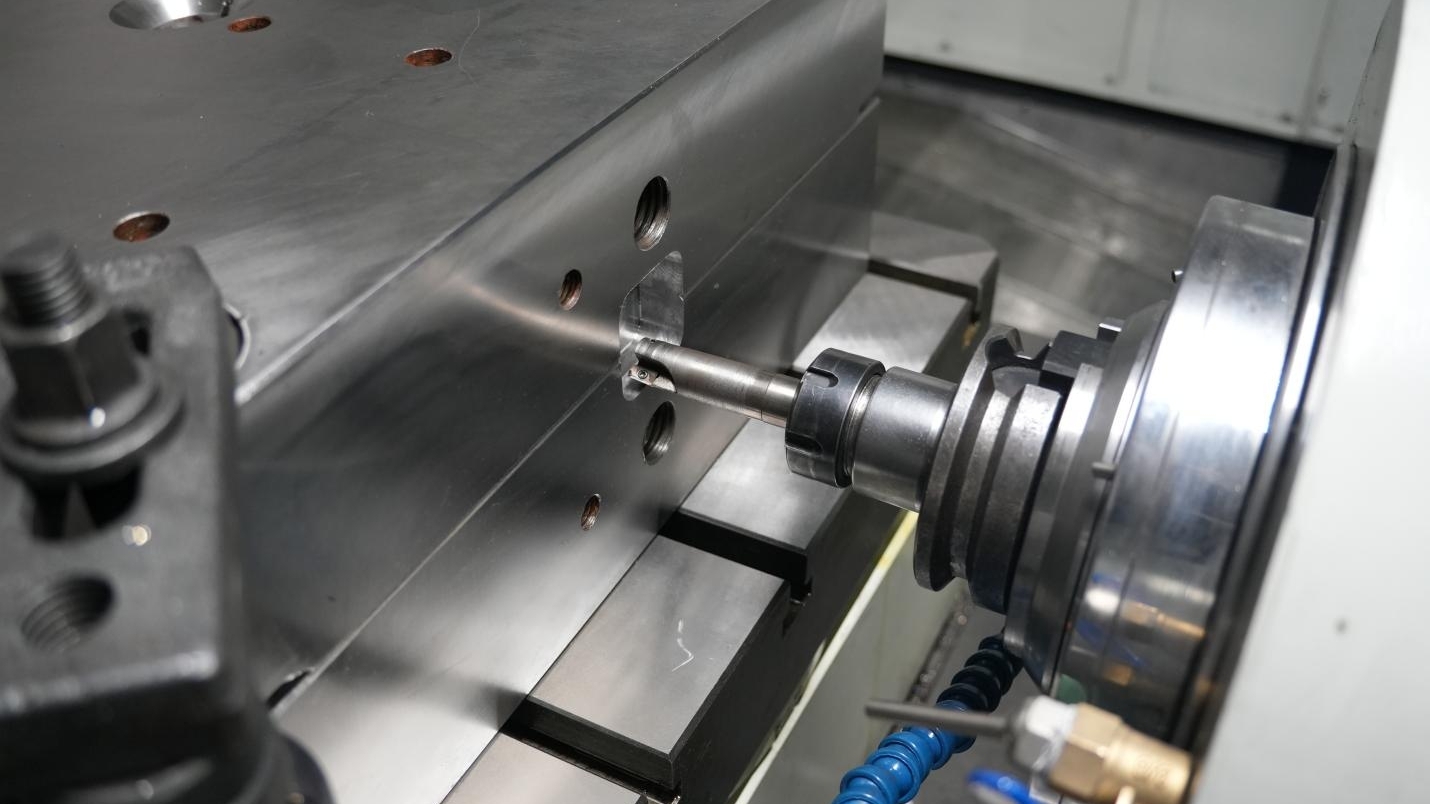
Spindle Interface
A 20 kg heavy face mill is mounted in the spindle taper of a horizontal machine. The disc-spring stack inside the drawbar releases instantly. The retention mechanism grips the pull stud at the end of the toolholder and generates up to 20,000 N of pull force. The hundreds of kilograms of radial thrust produced during heavy cutting are all borne by that taper interface.
In many U.S. shops, standard CAT50 holders are commonly used to machine 4340 alloy steel. The 7:24 taper design leaves a tiny flange gap. When spindle speed rises to 8,000 RPM, centrifugal force causes the mouth of the spindle bore to expand slightly like a bell. The toolholder is pulled inward by heavy drawbar force by about 0.015 mm. Z-axis depth of cut shifts, leaving a step mark on the workpiece surface.
BIG Daishowa developed the BIG PLUS dual-contact system in Japan. The spindle face and the holder flange make direct metal-to-metal contact. Dual positioning through both the taper and the face raises radial rigidity by 30%. A rough boring bar with a 300 mm overhang reaches inside a cast-iron housing, while tool-tip cutting vibration is held within 0.003 mm.
| Interface Type | Taper Ratio | Flange Diameter | Required Static Pull Force | Measured Bending Stiffness |
| Standard CAT50 | 7:24 | 98.4 mm | 25 kN | 1500 N/μm |
| BIG PLUS 50 | 7:24 | 98.4 mm | 25 kN | 2100 N/μm |
| HSK-A100 | 1:10 | 100.0 mm | 45 kN | 3000 N/μm |
German standard DIN 69893 defines the HSK-A100 short taper holder. It uses a 1:10 taper and a 100 mm flange diameter. The holder itself is hollow. Expansion grippers inside the spindle clamp it from the inside outward. The faster the spindle runs, the more centrifugal force increases the clamping force.
When machining titanium aerospace structural parts, spindle torque often exceeds 1,000 N·m. The HSK-A100 flange face includes two asymmetrical drive key slots. Drive blocks on the spindle nose engage these slots to transmit pure mechanical torque. The slender taper no longer has to carry the torsional load, so the chance of the holder slipping or sticking in the spindle bore is effectively eliminated.
Fretting wear occurs frequently during heavy roughing. A 150 mm corn cob cutter enters P20 mold steel, and cutting force creates microscopic vibration hundreds of times per second. Friction develops between the holder taper and the spindle bore. When the toolholder is pulled out, a rust-like red oxide residue can be seen on the surface.
Maintenance technicians regularly check spindle taper condition using a bluing method. A standard inspection bar coated with a very thin layer of Prussian blue is inserted into the spindle. The contact pattern left behind after removal reveals the condition of the taper:
· If contact coverage is below 85%, regrinding is scheduled
· Localized poor contact increases tool-tip runout to more than 0.02 mm
· A blank area at the large end face indicates bell-mouth deformation has developed
· Heavier contact at the bottom suggests severe load imbalance on the pull stud
The tool-change arm removes a U-drill with internal coolant from the magazine. As soon as the old holder leaves the spindle, the internal air line blasts out 6 bar of air. That jet clears away any tiny chips, as small as 0.05 mm, stuck to the taper bore. If even a few micron-level chips are trapped between the taper faces, the U-drill’s concentricity error exceeds 0.1 mm and the tool is effectively scrapped.
Cutting fluid at 70 bar is fed through a high-pressure rotary union at the rear of the spindle. The fluid passes through the center hole of the drawbar and enters the internal channels of the tool through the sealing O-ring at the toolholder flange. If that seal ages or cracks, the high-pressure emulsion can leak into the front spindle bearings. Once ceramic balls become contaminated with coolant, spindle life can drop by 90% within a matter of weeks.
The front section of a heavy-duty HMC spindle is fitted with four sets of ultra-precision angular contact ball bearings with an inside diameter of 110 mm. The large bearing pack sits extremely close to the holder face, dramatically reducing cantilever effect. As the face mill bites 15 mm-wide chips from a cast-iron blank, the bearing system withstands radial impact loads of up to 30,000 N.
A heavy-duty boring head can reach an overall length of 450 mm and weigh more than 18 kg. The operator assigns a heavy-tool label in the tool management system, and the machine then takes over the M06 tool-change sequence:
· The rotation speed of the tool-change arm is forcibly reduced by 40%
· The spindle motor completes micro-orientation locking within 0.1 seconds
· The arm disengages only after the system confirms drawbar force is within range
· The spindle accelerates to full speed within 0.5 seconds and returns to cutting
Many older HMC shops at McDonnell Douglas in the United States still run equipment using standard BT50 interfaces. Operators routinely use torque wrenches to tighten the pull studs at the end of the holders. The pull stud threads carry thousands of pounds of tensile load, and over time, fatigue creates microcracks. When a pull stud breaks during rough cutting, a 20 kg holder can shoot out of the spindle like a projectile.
Fewer Setups
A horizontal machining center (HMC) uses its B-axis rotary table to machine all four sides of a 2,000 lb mold base in a single clamping operation.
A traditional vertical machine requires six manual flips and re-clamping steps, each taking 45 to 90 minutes.
An HMC reduces setup operations to just one or two, saving nearly six hours of non-cutting downtime per part.
The standard dual pallet changer replaces a 1.5-ton pallet in just 12 seconds.
Operators load parts outside the machining zone while the spindle continues cutting. Spindle utilization rises from the typical 35% on conventional machines to more than 85%.
Geometric Tolerances
A valve plant in Houston handles 4,000 lb cast-iron valve bodies every day. After the first face is machined on a conventional machine, workers loosen four 3/4-inch hold-down bolts, and the internal stress in the heavy metal block is released instantly. The bottom face springs back by roughly 0.0003 inch.
When an overhead crane lifts and flips the valve body, tiny iron chips can easily become trapped under the support blocks. Even a chip only one-tenth the thickness of a human hair—just 0.0005 inch—can introduce an invisible tilt across the entire part.
With a dial indicator, the operator spends 40 minutes trying to recover the previous zero point on the new datum face. No matter how skilled the machinist is, the moment the clamps are tightened again, an unavoidable position error of 0.0015 to 0.002 inch is introduced.
An HMC locks the entire cast-iron block rigidly onto a square tombstone fixture and never loosens a single bolt during the process. The B-axis table, equipped with a high-precision rotary encoder, begins rotating under motor drive at 30 RPM.
The spindle face-mills the front of the valve body with a 6-inch cutter, then the table indexes exactly 90°. The spindle does not even need a tool change before it immediately starts boring the flange holes on the side. The 90-degree perpendicularity between the two faces is held firmly within 0.0002 inch.
An engine block plant in Detroit has extremely tight coaxiality requirements. A 24-inch camshaft bore must be machined from both ends toward the center. On conventional equipment, if one end is machined first and the block is then flipped to machine the other, the centerlines of the two bores are often offset by 0.0012 inch.
When the assembly worker inserts the camshaft, it binds during rotation, and vibration on the test stand exceeds the limit by 30%. On a horizontal machine, the rotary table turns the blank 180° in place, and the alignment error between the boring axes from both ends is only 0.0001 inch, allowing the bearing to slide in smoothly.
| Process Change Method | Positional Error (in) | Perpendicularity Error Between Adjacent Faces (in) | Coaxiality Error of Holes at Both Ends (in) |
| Crane Flip (3 times) | 0.0025 | 0.0018 | 0.0015 |
| Manual Clamp Loosening/Tightening (2 times) | 0.0012 | 0.0009 | 0.0008 |
| Automatic B-axis Rotation (0 times) | 0.0002 | 0.0001 | 0.0001 |
Temperature variation in the shop has always been a frustrating source of interference. At an aerospace parts plant in Seattle, a titanium wing frame measuring 60 inches long has to move through three workstations. The morning temperature starts at 65°F, then the shop rises to 78°F by afternoon, and thermal expansion stretches the titanium by 0.003 inch.
A horizontal machine compresses every machining operation into one enclosed, temperature-controlled chamber. The coolant, regulated by a refrigeration compressor, stays constant at 68°F and pours over the titanium blank like a waterfall. Surface temperature fluctuation stays within 2 degrees, and the dimensions remain centered in the tolerance band.
Hydraulic fittings sealed with O-rings are extremely sensitive to blend marks on the surface. A ball end mill machines a complex curved chamfer on the part. If that surface is cut in two separate setups, a tiny step 0.0008 inch high will inevitably appear where the two toolpaths meet.
High-pressure hydraulic oil will slowly leak out through a gap thinner than paper. With its one-setup advantage, the HMC lets the spindle run the entire curved profile in one continuous pass. The blend line disappears completely, and the surface roughness tester reports a steady 16 microinch Ra.
The rotary encoder inside the B-axis is a glass disc engraved with extremely fine lines. Each full turn produces 360,000 pulse signals. When machining a complex valve block with a 45-degree angled hole, the table stops at a non-integer angular position.
The spindle changes to a high-speed drill and enters the stainless steel blank at an angle. Because the part has not been repeatedly removed and reinstalled, the intersection between the angled hole and the main bottom hole is exceptionally precise. The coordinate measuring machine (CMM) report shows a positional deviation of only 0.003 mm.
| Inspection Batch (100 pcs) | Time Required for Full CMM Inspection (hours) | Scrap Rate from Geometric Tolerance Failure |
| Old equipment with multiple setups | 14.5 | 6.8% |
| New equipment with one setup | 4.2 | 0.4% |
At that Seattle plant, a single aerospace titanium blank can cost as much as $12,000. In the past, during the fourth manual setup, one small mistake in reading the dial indicator could shift the drill by 0.005 inch, turning the entire expensive blank into scrap metal.
By leaving all dimensional relationships to the machine’s cast-iron structure instead of the operator’s touch, variation from manual handling is eliminated. The yield report from the inspection room shows the pass rate for expensive materials rising from 89% all the way to 99.4%.
Downtime Reduction
A mold shop in Ohio regularly cuts P20 tool steel blocks weighing 3,500 lb. On vertical machines, workers used to loosen hex nuts with large wrenches, clean chips from the table, edge-find the blank with a dial indicator, and tighten the clamps again. The minute hand on the dial would move through 55 minutes while the spindle sat completely still.
On an HMC, the load station is completely separate from the cutting chamber, giving workers a safe three-hour window to prepare the next job. Using preset torque wrenches, they can take their time securing the next large blank onto a 400 mm-wide pallet. Meanwhile, inside the machining chamber just one sheet-metal wall away, the spindle is milling the previous aerospace aluminum plate at 12,000 RPM. The machine status light stays green the entire time.
The two pallets swap in only 11.5 seconds. The heavy enclosure doors slide open, a stout hydraulic arm pushes the finished pallet out to the unload position, and the pallet carrying the new blank rotates and slides into the chamber. The moment the control reads the M60 code, the spindle drops and resumes cutting. Effective cutting time on a single machine jumps to 88%.
In the past, whenever a large metal part needed machining on multiple faces, the shop crane had to be called in repeatedly. A 3-ton steel block would hang in midair while two workers in thick leather gloves struggled beneath it to flip it 180°. An HMC’s built-in B-axis rotary table can rotate on its own with 0.001° resolution. As the spindle moves back and forth along X and Y, it can finish the front, right, and left faces of the blank in one minute without human intervention.
· On vertical machines, spindle idle waiting time exceeds 4 hours per shift
· On horizontal machines, spindle idle time is reduced to under 45 minutes per shift
· For a single complex mold base, crane-assisted flipping drops from 6 times to just 1 loading and 1 unloading lift
· Safe off-machine clamping accounts for 0% of total downtime
An automotive parts workshop in Stuttgart, Germany, equipped its HMC with an oversized tool magazine—a multi-layer matrix rack that holds 320 tools. Operators preload three identical 1/2-inch carbide end mills into it. The machine control reads spindle motor load every second. The first end mill continues cutting for 200 hours.
As the cutting edge dulls, spindle load exceeds the preset 15% alarm threshold. The machine immediately stops feeding forward and retracts the tool to a safe height. The automatic tool changer lunges out and replaces the worn cutter in just 1.8 seconds. A brand-new backup tool is loaded into the spindle, and heavy cutting resumes. Even with no one in the shop during the night shift, the machine continues working for 14 hours.
A rectangular cast-iron tombstone fixture has four faces. On those four faces, workers mount two titanium turbine blades each, for a total of eight blanks on one pallet. Once the spindle finishes the first part, it only needs to shift a few millimeters and begin cutting the next one. The parts remain fixed securely on the fixture and never have to be removed and re-aligned mid-process.
· The stock of same-spec wear replacement tools can reach 5 to 10 pieces
· Abnormal increases in spindle motor current are detected at millisecond speed
· Total time for removing the old tool and loading the new one is just 1.8 seconds
· Hot-swapping toolholders through the front door does not interrupt cutting inside the chamber
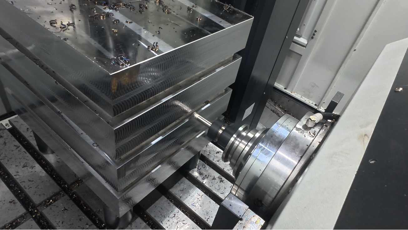
Metal cutting generates large volumes of curled chips. On a vertical machine, chips pile up on the horizontal table and cover the datum surfaces completely. Every hour, the operator has to press pause and blow chips out of the corners of the fixture with high-pressure air. On a horizontal machine, the spindle is mounted sideways, so gravity pulls all chips downward.
The high-pressure through-tool coolant system continuously flushes the cutting zone at 1,000 PSI. Chips have no chance to stick to the vertical sides of the tombstone fixture. They slide down the 30-degree sloped sheet-metal chute at the bottom and rattle into the chain conveyor below, which carries them out of the shop. The operator no longer has to stop the machine midway just to clear chips.
An aerospace manufacturing plant in Texas purchased a 40-foot linear rail. Three horizontal machining centers are lined up along it. In the middle of the rail sits a servo-driven stacker crane that runs back and forth around the clock. On both sides of the crane, 24 three-tier pallet storage racks are neatly arranged.
During the day shift, two workers load all the aerospace-grade aluminum blanks onto pallets and assign the corresponding machining programs on screen. At 5 p.m., they clock out and go home. The stacker crane then follows the preset sequence, pulls a waiting pallet from the rack, opens the side door of the machine, and delivers the pallet into the machining chamber that has just become available.
· The servo-driven stacker crane travels at 80 meters per minute along the rail
· The robotic pallet insertion and extraction positioning accuracy is held within 0.05 mm
· Three machines and 24 fully loaded pallets can run all night with zero human supervision
· The probability of an internal infrared sensor being blocked by chips and triggering an alarm drops by 95%
Once a part is finished in the chamber, the stacker crane pulls it out and returns it to its rack. The next idle machine immediately takes over the next blank. Over the weekend, for a full 48 hours, the three spindles do not stop once. Together they machine 120 complex aerospace brackets in one continuous run. At 8 a.m. on Monday, the shop doors roll open, and workers remove the bright finished parts, pack them, and ship them out.
Heavy Workpiece Handling
A heavy equipment plant outside Chicago machines ductile iron pump housings weighing up to 8,500 lb every day. On vertical mills, workers used to spend 25 minutes just rigging the part to the overhead crane. Two operators would loop four Kevlar slings rated for 10,000 lb around the casting lugs on both sides of the blank.
Even the slightest swing from a nearly 4-ton iron casting could dent the sheet-metal enclosure of a nearby machine.
The blank would hang in the air, ready to be flipped to machine the bottom base. The crane operator had to lower the thick steel wire rope at the painfully slow speed of 0.5 inch per second. Workers beside the machine placed three 2-inch-thick copper support blocks beneath it, because a hard cast-iron surface striking a hard machine table could easily leave visible dents.
Once the horizontal machining center arrived, that kind of overhead rigging acrobatics disappeared. The 8,500 lb pump housing could be placed securely onto the wide external load station. Standing on anti-slip rubber mats, workers used a pneumatic torque wrench to lock the blank onto the base. All fastening was done safely at floor level, with no one craning their neck up at the overhead crane.
· Sling wear dropped by 80% over six months
· The purchasing department no longer had to keep buying new high-strength nylon slings
· The risk index for crushing injuries reported by Michigan labor authorities fell to the lowest category
The cast-iron pallet carrying the large pump housing weighs more than 12,000 lb including the part. Inside the machine, the hydraulic rotary table drives a heavy gear using 2,000 PSI hydraulic pressure. This entire mass of metal slides smoothly into the machining chamber in 14 seconds. The motion is so stable that a cup of water placed on the pallet would not spill a drop.
Once the spindle finishes the front face, the B-axis rotates the blank 90° in place to cut the left side. On an old vertical machine, the spindle would have to stop after the front face, and the operator would climb up, loosen six large M24 hold-down bolts with a heavy adjustable wrench, and then wait 15 minutes for the shop’s 20-ton bridge crane to arrive.
There were only two large overhead cranes in the shop, while five large machines on the floor all had to compete for them, so the waiting time for a crane often exceeded the actual spindle cutting time.
A wind gearbox factory in Bavaria, Germany, calculated the daily time cost in detail. To machine a planetary carrier 1.5 meters in diameter and weighing 6,000 lb, operators had to flip it three times in the air. Lifting, rotating, and re-indicating it again required at least two skilled workers and 45 minutes. With a horizontal machine, the entire job requires only two lifts: one at loading and one at unloading.
· Crane handling time for a single large gear carrier dropped from 135 minutes to under 25 minutes
· The number of times operators had to climb onto a waist-high machine table fell from 14 times a day to zero
· Electricity consumed by repeated crane motor starts dropped by 40 kWh per day
Moving and adjusting heavy metal blocks is both physically exhausting and dangerous. Workers wearing steel-toe boots have to push and guide heavy parts on metal surfaces covered in slippery cutting fluid. One misstep or collision with a piece of scrap weighing several hundred pounds can cause serious back strain. In Ontario, Canada, compensation claims for this kind of back injury can reach tens of thousands of dollars.
The external load table of an HMC sits at an ergonomic height of about 36 inches above the floor. Operators do not have to bend over or reach deep into the machine for hard-to-access clamps. A hydraulic fixture system takes over the burden of manual fastening. With one press of the green button on the control panel, four cylinders extend immediately and apply 3,000 lb of clamping force to lock the blank in place.
Workers in their sixties, nearing retirement, can now comfortably tend two heavy machining systems by themselves without wrestling with long, heavy wrenches.
A heavy valve manufacturer in northern Italy specializes in large forged 400-series stainless steel parts. These extremely hard alloy blanks are covered with sharp flash along the edges, almost like knife blades. In the past, when workers rigged and re-rigged them with wire rope, those sharp edges could cut through three nylon slings rated at 5 tons in a single month. The pallet exchange system keeps the heavy block fixed in one place.
Tungsten carbide tools can cut continuously for 10 hours, machining those dangerous burrs into smooth 45-degree chamfers. Inside the enclosed machine, the forging completes rough milling and finish boring on all four faces in one uninterrupted process. When the metal block slides back out to the operator at the load station, the surface finish has already been brought to a bright 32 microinch Ra. The operator can simply slip a clean fabric sling around it and move it onto the shipping pallet.
Reducing repeated crane handling also helps solve a large part of the rust problem. In Houston, summer humidity can climb to 85%. As cast-iron parts are lifted, turned, and re-positioned around the shop, sweat-soaked gloves touch the metal constantly. During the hour or more spent flipping the part and re-indicating it, a thin yellow layer of rust can begin forming on the exposed metal surface.