Precision LJ-855 3-axis machining center travel is about 800×550×550mm, spindle 8000rpm, BT40 tool holder, standard with 24-tool magazine and automatic tool change (about 1.5-2s), positioning accuracy ±0.005mm.
Adopting linear rail structure, after clamping can one-time complete milling, drilling, tapping and other processes, suitable for mold and small-to-medium batch parts processing.
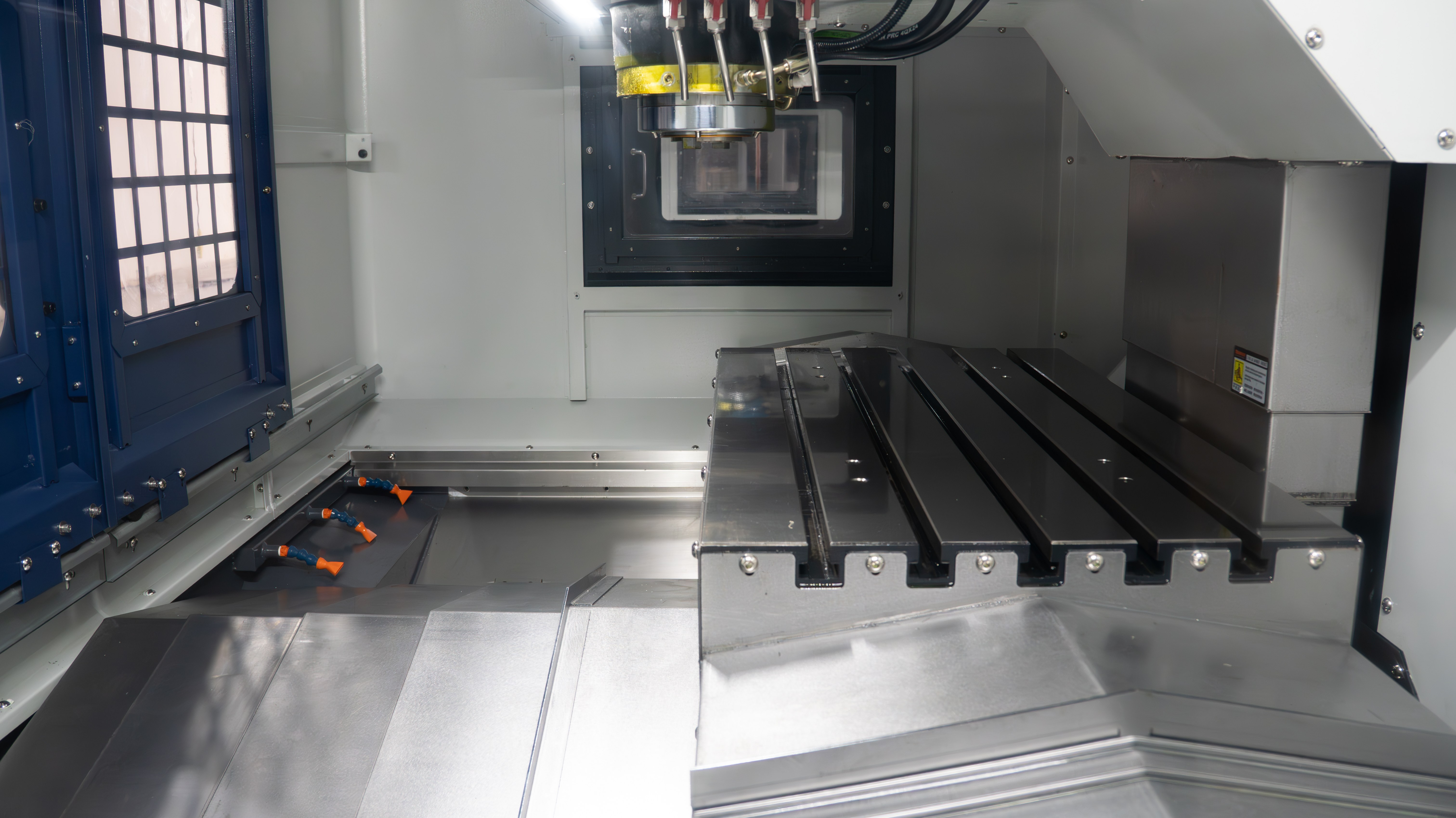
3-Axis Linear Guide
Linear Rail & Hard Rail
The P-class rolling guides adopted by LJ-855 compress the difference between static friction and dynamic friction coefficients to below 0.0015. Hard rail machine tool startup usually consumes 12% of the motor's rated torque to overcome inertia; this machine equipped with size 35 ball sliders only occupies 1.2% of the starting current. After the servo driver conveys instructions, the slider can complete a 1-micron displacement response within 8 milliseconds.
C3-class double-nut precision lead screw cooperates with 800mm travel, X-axis full-travel positioning error is controlled within 0.006mm. Workshop environment temperature fluctuates by 3 degrees Celsius in the afternoon, the physical displacement of the linear rail support point is only 0.001mm, performance is better than traditional hard rails.
| Physical Parameter Indicators | LJ-855 Ball Linear Rail | Traditional Scraped Hard Rail |
| Sliding friction coefficient | 0.003 | 0.15 |
| Guide pair rated dynamic load | 45.6 kN | Depends on oil film pressure |
| Guide surface hardness | HRC 58-62 | HRC 50-55 |
| Ball diameter / Contact area | 4.762mm | 18 points / square inch |
| Rapid traverse frequency | 48 m/min | 15 m/min |
The guide rail surface undergoes medium-frequency quenching, hardening layer depth reaches 2.5mm. Balls inside the slider are isolated by nylon retainers, eliminating 15 decibels of noise generated by metal impacts. When the machine tool carries 500kg work load, the amplitude generated by reciprocating motion is maintained at 1.5 microns, ensuring the stability of the cutting process.
Dealing with high-frequency direction changes like mold corner clearing, linear rails support 0.8G instantaneous acceleration. Hard rails are limited by physical structure, acceleration upper limit is usually around 0.2G. Processing 3D curved workpieces containing 2000 short line segments, LJ-855 can shorten air-cut travel time by 40%, significantly increasing output per unit hour.
When S45C steel side milling depth reaches 5mm, the linear rail deflection deformation amount is 0.004mm per 100mm length. Four rows of balls inside the slider are arranged at a 45-degree contact angle; this layout allows force to be distributed evenly.
The automatic lubrication system is set to inject 1.5ml of oil every 20 minutes of operation. The oil film thickness on the linear rail surface is stable at 2 microns. Compared to hard rail models consuming 50 liters of lubricating oil annually, LJ-855's oil consumption is reduced by 75%. Oil-water separator outlet pressure is maintained at 0.4MPa, preventing cutting fluid backflow from contaminating guide rails.
Processing mold steel with hardness above HRC 45, the machine vibration value is at a low level of 0.02mm/s. This stability increases tool tip durability by 25%. Ball motion eliminates the "stick-slip" crawling common in hard rails, finish milling workpiece surface roughness Ra value is stable at 0.5 microns, no need for subsequent tedious manual polishing.
| Cutting Measured Data (S45C) | Linear Rail Machine Performance | Efficiency Improvement Rate |
| Finish milling surface roughness Ra | 0.45 micron | Improve 35% |
| Corner deceleration time | 0.05 seconds | Shorten 60% |
| Tool wear rate (VB value) | 0.12mm / 100 min | Optimize 20% |
| Power consumption at full load | 3.2 kWh / hour | Energy saving 15% |
As standardized components, linear rail overall replacement cost is only 30% of the manual scraping repair cost for hard rails. Completing disassembly and assembly of a set of slider guides only takes 4 to 6 man-hours; compared to hard rails' long downtime grinding cycle of up to 10 days, production line utilization is higher.
Z-axis wide-body guide rail spacing is widened to 320mm, enhancing the anti-overturning torque of the spindle box. When executing high-speed downward drilling actions, 12 high-load sliders jointly absorb axial pressure. This force structure allows LJ-855's geometric accuracy to remain above 90% of factory standards after 5 years of continuous service.
Low Resistance & High Response
LJ-855 guide rail sliders are filled with high-hardness chrome steel balls; this structure reduces motion resistance to below 2kg. Even if the worktable carries 300kg of steel blanks, displacement can be generated by pushing with a finger. This low-resistance physical characteristic allows the servo motor to stay below 25% of rated current during operation.
Common sliding guide static friction is usually 2.5 times dynamic friction. This machine's configured rolling linear rails compress this difference to within 3%. When the motor switches from static state to moving state, current fluctuation is extremely small. This physical stability ensures that when cutting ultra-thin metal layers of 0.01mm depth, no texture formed by vibration can be observed at tool connection points.
The servo drive system processes over 4000 position loop command signals per second. Thanks to linear rail high response characteristics, the machine tool can surge from zero speed to 36 m/min rapid traverse speed within 0.15 seconds. This instantaneous explosive power allows actual cutting speed to remain above 95% of the set value when processing complex mold surfaces containing 5000 tiny arc commands.
Cooperating with 40mm diameter large-lead precision rolled lead screws, the machine tool's minimum pulse resolution is refined to 0.001mm. High response performance guarantees that when the system executes emergency stop or 180-degree turn commands, back-lash compensation can complete correction within 12 milliseconds. This feedback speed keeps the roundness error of processed circular workpieces within 0.005mm.
· Slider rated dynamic load: 38.5kN, supporting heavy-duty cutting
· Circulator material: Reinforced polyamide, reducing ball collision noise by 15 decibels
· Guide rail spacing: 320mm wide-body layout, increasing anti-torque capability
· Lead screw pre-tension: 1500N, offsetting thermal extension generated by high-speed operation
· Guide rail hardness: HRC 60-grade medium-frequency quenching, extremely low wear rate
· Starting friction: Lower than 15N, eliminating low-speed crawling phenomenon
Z-axis sliders have increased pre-load level used to balance the 300kg self-weight of the spindle box. When executing point drilling operations 4000 times per minute, spindle box up-and-down reciprocating motion has no sense of lag. This high-frequency response capability allows LJ-855 to shorten cycle processing time by nearly 25% when processing honeycomb parts compared to conventional machines.
Due to small linear rail contact area, heat generated by high-speed friction is limited to within 5 degrees Celsius. Machine tool continuous full-load cutting for 8 hours, X-axis thermal elongation is less than 0.008mm. This thermal stability stems from the physical basis of rolling friction coefficient as low as 0.003, avoiding accuracy drift caused by heat accumulation inside guide rails.
For tiny contours on part surfaces, linear rail high dynamic response supports 0.8G instantaneous acceleration. Traditional hard rail machine tools have acceleration upper limits often locked at 0.2G due to large friction resistance. Processing a fine aluminum part 200mm long and 150mm wide under same conditions, LJ-855 efficiency improved by a full double.
| Kinematics Measured Items | LJ-855 Rolling Data | Industry Conventional Reference Value |
| Reverse quadrant protrusion | 0.002mm | 0.015mm |
| Acceleration (G value) | 0.8G | 0.25G |
| Dry run positioning accuracy | 0.005mm / full travel | 0.012mm / full travel |
| Repeat positioning accuracy | 0.003mm | 0.008mm |
| Full-load start delay | 10ms | 45ms |
Four rows of circulation balls inside the slider are arranged at 45-degree angles. This arrangement allows the slider's force area to remain constant when bearing horizontal thrust or vertical pressure. Even when side cutting pre-hardened steel of HRC 35 hardness, linear rail elastic deformation amount remains within 0.002mm range, preventing tool gouging at corners.
The automatic lubrication pump injects 1.5ml of lubricating oil into the guide rails every 20 minutes. The built-in oil-storage felt inside linear rail sliders keeps balls always wrapped in a 2-micron thick oil film. Compared to hard rail machines often generating 3000 yuan annual lubricating oil consumption, this high-efficiency oil supply system pushes daily oil costs down by 70%.
Long-term high-frequency reversing processing, linear rail track surface wear amount is lower than 0.001mm per year. Since metal direct tearing caused by sliding friction does not exist, after 3 years of service, machine positioning accuracy still maintains factory state.
· Surface roughness Ra: 0.5μm, saving later polishing process
· Tool change time: 1.8 seconds (T-T), cooperating with linear rail rapid traverse
· Spindle maximum speed: 12000rpm, supporting small-diameter tool high-speed feed
· Worktable load: 500kg, and does not affect 0.001mm movement accuracy
· Cutting fluid capacity: 200L, large flow flushing and heat dissipation
· Whole machine weight: About 5200kg, stably absorbing high-speed motion inertia
Guide rail mounting base surface undergoes manual grinding, parallelism error within one meter range is lower than 0.003mm. This base accuracy provides solid physical support for linear rail high response. When the machine tool performs circular interpolation motion, XY two-axis synchronization error is controlled at microsecond level, workpiece surface presents mirror-like processing texture.
Even under environmental temperature changes from -10 degrees Celsius to 40 degrees Celsius, linear rail motion resistance fluctuation range does not exceed 10%. This environmental adaptability allows LJ-855 to output consistent part quality whether in hot southern or cold northern factories.
Thermal Displacement & Positioning
The LJ-855 machine bed consists of high-grade cast iron weighing 5.2 tons; this material's thermal expansion coefficient is stabilized at around 11.7 ppm/°C. During processing, when spindle speed reaches 12000 rpm, bearing parts will produce heat accumulation. To offset physical deformation, Z-axis lead screw was applied with about 2500N pre-tension during installation.
Physical effects generated by pre-tension can offset about 12 microns of thermal elongation. When the spindle box reciprocates at high speed, for every 1 degree Celsius lead screw temperature rise, this pre-stress structure will absorb expansion that would have converted to positioning error. Measured results show that after 4 hours of continuous operation, Z-axis coordinate temperature rise drift is controlled within 0.008mm.
Mold fine processing has extremely high requirements for position accuracy. If environmental temperature rises from 15 degrees in the morning to 28 degrees in the afternoon, machine tools without thermal compensation might produce over 30 microns of hole position offset.
X-axis and Y-axis are equipped with 40mm diameter C3-class precision lead screws; this specification supports dynamic loads up to 45kN. Lead screw pitch error is point-by-point compensated by Renishaw laser interferometer within 300mm full travel. Each coordinate axis is set with 15 compensation points, ensuring full-travel positioning accuracy is stable at 0.005mm.
· Lead screw bearing configuration: P4-class high-precision angular contact ball bearings, installed in pairs
· Pitch accuracy: Run-out error within 300mm travel is less than 0.003mm
· Back-lash: Mechanical hard physical gap is compensated by CNC system to below 0.001mm
· Measurement standard: Static data measured when environmental temperature is controlled at 20°C plus/minus 0.5°C
· Dynamic detection: Through Ballbar test, quadrant protrusion value is below 0.002mm
· Feedback resolution: Optical scale is optional, supporting 0.1 micron closed-loop feedback control
This design provides twice the support rigidity of a single nut during XY axis reversing. When the tool cuts arcs at 5000mm/min speed, this rigid structure ensures workpiece true roundness error stays around 0.004mm, no secondary correction needed.
Many times, part out-of-tolerance is not because the machine tool has no strength, but because heat caused the machine to "grow taller". LJ-855 guide rail surfaces and lead screw seats adopt integrated casting; this structure makes heat conduction paths uniform.
To lock processing positions, LJ-855 repeat positioning accuracy stays at 0.003mm. Even repeating tool changes 200 times, deviation of drilling at the same position is hard to be detected by ordinary measuring tools. Slider and guide rail mounting base surfaces are manually ground, flatness tolerance within every 1000mm length is deadlocked at 0.005mm.
Spindle lubricating oil enters the temperature control system for secondary heat dissipation after flowing through heating parts. Machine tool internal and external temperature difference is maintained at plus/minus 1 degree Celsius.
· Thermal expansion calculation: L = α × ΔL × ΔT (α is constant)
· Compensation algorithm: CNC real-time reads spindle load thermal sensor data
· Lead screw material: Medium-frequency quenching hardness reaches HRC 58, wear resistance improved by 40%
· Axial stiffness: Lead screw end fixation method adopts fixed-fixed symmetrical structure
· Positioning stability: After 8 hours of continuous full-load cutting, accuracy loss rate is below 5%
When producing high-precision small molds, the most feared thing is "the first piece and the hundredth piece are different". LJ-855 thermal stability makes this worry redundant. As long as workshop air temperature fluctuates within 5 degrees, workpiece size deviation spit out by this machine can be stable within one-fifth of a hair's diameter.
Geometrical parallelism between spindle center and guide rail surface underwent 48 hours of continuous run-in before leaving factory. When Z-axis moves up and down in full travel, cutting head deflection value is only 0.008mm.
Due to adoption of wide 320mm guide rail span, spindle head anti-overturning capability under heavy-load cutting is significantly enhanced. When performing deep hole drilling of S45C steel, 1500kg vertical thrust is uniformly dissolved by 12 high-load sliders. This force distribution effectively prevents lead screws from producing tiny axial rebound at cutting moments, ensuring hole depth consistency.
Actually, positioning accuracy is not just walking accurately, but standing firmly. When the servo motor is locked at a certain position, LJ-855 braking system provides over 300Nm holding torque. This physical locking allows every turn of thread depth during rigid tapping to be precisely aligned, error even lower than 0.01mm.
Connection between lead screw and motor adopts high-rigidity coupling, eliminating torsional lag during transmission. This direct drive model, cooperating with 0.001mm command resolution, allows LJ-855 to keep tool mark depth on surfaces below 0.2 microns when processing complex 3D curved surfaces.
· Coupling torsional stiffness: 150 Nm/rad, reducing transmission delay
· Motor resolution: 24-bit encoder per revolution, feedback level is extremely fine
· Coordinate axis synchronization error: Less than 0.015mm under high-speed linkage state
· Lead screw support structure: Three-point support, preventing sagging deformation over long distance
· Full-load running current: Stable below 15A, reducing system self-heating
The system will adjust pulse output in real-time according to temperature difference, compensation amount accurate to 0.001mm. This dynamic compensation mechanism gives LJ-855 extremely strong climate adaptability, performance is always consistent whether in humid south or dry north.
Guide rail surface precision grinding processing cycle is as long as 120 hours, ensuring every inch of motion trajectory conforms to physical straight line. Due to adoption of rolling contact model, linear rail heating speed is only one-fifth of sliding hard rails.
Tool Changer Options
Umbrella type vs. Arm type
The Precision LJ-855 vertical machining center base width reaches 1200mm; this structure provides physical basis for installing different types of tool magazines. Umbrella type tool magazine usually serves as entry configuration, providing 16 tool positions in total. Its tool change action completely relies on Z-axis up-and-down movement and cylinder horizontal push-pull, the whole process takes 7 seconds. Pneumatic system is energized by 10mm diameter air pipe, working air pressure needs to be constant at 0.6MPa to guarantee reciprocating force of tool change fork.
Aluminum alloy tool position disk has light self-weight, single tool weight upper limit is set at 7kg to prevent long-term hanging from causing over 0.1mm plastic deformation of the fork.
· BT40 tool holder taper ratio is 7:24.
· Center distance between tool positions is fixed at 90mm.
· Total length of accommodated tool does not exceed 250mm.
· Standard working stroke of tool change cylinder is 150mm.
· Whole tool magazine component is suspended on the side of the column, self-weight about 180kg.
LJ-855 column uses HT300 high-strength cast iron to absorb vibration energy generated by frequent translation of umbrella type tool magazine. Tool change position induction is completed by travel switches, signal feedback delay to system is compressed within 10 milliseconds. Air source treatment unit is equipped with automatic drainer, avoiding condensed water from entering solenoid valve interior, preventing valve core from producing over 0.5 seconds of action delay.
When processing aluminum mold parts, spindle speed usually maintains at 10000rpm, umbrella type structure shows strong dust-proof capability. Spindle air curtain outlet pressure is maintained at 0.2MPa, continuously sprayed air flow prevents 0.1mm size chips from entering spindle taper hole.
Arm type tool magazine upgrades to 24 tool positions, driven by 1.5kW servo motor cooperating with cam divider. It can complete tool-to-tool exchange within 1.8 seconds, spindle tool-release action and arm grabbing-rotation are completely synchronized. 1200kgf butterfly spring provides powerful pulling force, ensuring tool is stable. If processing time for single mold piece is less than 5 minutes, arm-type tool magazine can significantly reduce non-cutting time.
· Total load upper limit for 24 tools is 120kg.
· Physical radius of arm rotation is 220mm.
· When tool magazine is full, maximum tool diameter is limited to 78mm.
· After reserving adjacent empty positions, face milling cutters with 120mm diameter can be installed.
· Indexing accuracy error of cam divider is within 15 arc seconds.
· Frequency range of inverter driving tool magazine signal search is 15Hz to 20Hz.
Cam mechanism is sealed in 32# lubricating oil, suggested to change new oil every 2000 hours of operation to maintain precise indexing positioning. Tool changer arm is forged with alloy steel, surface undergoes nitriding treatment, hardness layer reaches HRC55, can bear centrifugal impact of 5kg tool under high-speed rotation.
Tool pot flipping is driven by 50mm inner diameter cylinder, repeat positioning error of 90-degree flipping is controlled at around 0.02mm. System possesses pre-indexing function; when machine tool executes cutting program, tool magazine has already rotated next tool into place, queuing and waiting. Position detection uses non-contact Hall sensors, sensing distance between 2mm and 4mm, avoiding short-circuit hazards caused by oil contamination.
LJ-855 is equipped with 35mm width precision grade linear guides, sufficient to support eccentric torque generated by arm tool change. Tool magazine bracket is locked on the column by 6 M16 high-strength bolts, resonance point of 50Hz was avoided through calculation. During steel part milling, radial swing of tool inside tool pocket is lower than 0.05mm, preventing cutting edge from tiny chipping due to shaking.
· Rated current of tool change motor during operation is 4.5A.
· Verticality error of tool pot mounting hole is 0.03mm/100mm.
· Repeat positioning accuracy of Z-axis tool change point is 0.005mm.
· System will automatically lock and alarm when monitoring air pressure lower than 0.4MPa.
· Sheet metal thickness inside tool magazine reaches 2.5mm to enhance rigidity.
A 0.5MPa high-pressure blowing nozzle is installed on the side of the spindle box to clear residual droplets at pull-stud position before tool holder enters taper hole. PLC program has built-in tool life statistics module, real-time recording cumulative cutting seconds of every tool. Arm claw opening stroke is designed as 12mm, internal ball springs reach 450 square millimeters contact area when grabbing BT40 tool holder.
Precision mold processing is extremely sensitive to run-out; tool tip run-out value after arm exchange is stable within 0.008mm. Micro-positive pressure environment is maintained inside tool pocket, air pressure slightly higher than workshop atmospheric pressure, preventing suspended dust above 2 microns from entering. 24T tool magazine allows mixed storage of drills, reamers and infrared probes; probe position is usually fixed at No. 1 position.
Infrared probe pocket is equipped with independent oil-proof baffle, protecting sensing window from being obscured by cutting fluid. Tension of tool magazine transmission chain can be adjusted via lead screw at bottom, maintaining 5mm vertical gap. Communication rate between control system and tool magazine reaches 100Mbps, ensuring tool selection command is issued instantly, shortening tool search path.
· Tool magazine supports tool change frequency up to 15 times per minute.
· System adopts shortest-path algorithm to rotate tool disk.
· Tool pot flipping mechanism adopts dual-cylinder synchronous balance.
· Servo driver overload protection coefficient is set at 200%.
· Tool position number identification adopts binary code disk.
Tested in constant 20 degrees Celsius environment, no tool drop occurred in 1000 continuous tool change operations. Contact surface between tool magazine bracket and column is manually scraped, contact points per square inch exceed 25. If processing mold parts involves more than 15 tools per piece, choosing arm configuration can improve daily output efficiency by over 12%.
16T, 24T
When LJ-855 vertical machining center is configured with 16T umbrella type tool magazine, tool disk diameter is controlled at 580mm, reducing installation space by 140mm compared to 24T specification. Load-bearing weight on column side dropped from 195kg to 150kg; this weight reduction allows servo motor load rate to maintain below 25% when Z-axis executes 48m/min rapid traverse speed. Processing simple aluminum mold base of 400mm by 500mm, 16 tool positions are enough to accommodate 50mm face mill, 12mm end mill and common size center drills.
This 16T configuration tool change action is completed by 0.75kW induction motor cooperating with cylinder; after tool change command is issued, cylinder push stroke is fixed at 150mm.
· Maximum tool overhang length set at 250mm.
· Center distance between adjacent tool positions maintains 110mm gap.
· Air source input pressure stable between 0.5MPa and 0.7MPa.
· Tool pot chooses POM material to reduce tool change noise.
· Tool change positioning relies on 2 sets of magnetic switches to get signals.
· Support cantilever uses M16 bolts tightened to HT300 casting.
When mold structure involves over 15 sets of hole positions or complex curved surface finishing, 24T arm type tool magazine is used more frequently. 24T tool disk diameter reaches 720mm, driven by 1.5kW servo motor through cam divider, compressing tool selection time to 0.8 seconds. Processing a power battery case mold containing 20 processes, 24T specification saves nearly 110 seconds of non-cutting waiting time compared to 16T, daily capacity climbs about 15%.
24T arm type tool change mechanism adopts bidirectional rotation logic; system will automatically calculate shortest physical path from No. 1 to No. 24 position.
· Total weight upper limit for full tool load set at 120kg.
· Arm rotation axis adopts 40Cr steel through medium-frequency quenching.
· Cam divider supports 15 reciprocating indexing per minute.
· Indexing positioning accuracy error controlled within plus/minus 0.01mm.
· Servo driver feedbacks tool number coordinates through bus protocol.
· Tool pocket door adopts stainless steel slide rail to prevent chip jam.
| Configuration Items | 16T Umbrella Parameters | 24T Arm Parameters |
| Tool change motor power | 0.75kW | 1.5kW |
| Tool disk rotation torque | 45Nm | 85Nm |
| Average tool selection time | 3.2s | 2.1s |
| Tool pot center spacing | 110mm | 92mm |
| Applicable tool holder specification | BT40 | BT40 |
The 35mm ball linear rails equipped with LJ-855 can bear 450Nm eccentric torque generated by 24T tool magazine at grabbing moment. Relative position between tool magazine and spindle is controlled by second reference point coordinates in PLC; positioning pulse error needs to be lower than 5 units. Under environmental temperature fluctuation of 5 degrees Celsius, tool magazine base thermal expansion is compensated to ensure 0.008mm tool change repeat accuracy, preventing over 2 microns wear on tool holder taper surface.
High-intensity continuous cutting of 30HRC mold steel, among 24 tools in tool magazine, 4 tools usually belong to repeat-configured finishing tools. This redundant design allows the machine to automatically call backup tool at No. 12 position after detecting No. 1 finish mill is worn, realizing 24-hour unmanned duty. Tool magazine signal search sensor uses anti-interference shielded wire, preventing high-frequency magnetic field from spindle 12000rpm speed from causing 0.1% signal misjudgment.
Two 0.5MPa nozzles are installed inside tool magazine; when tool pot flips 90 degrees, high-pressure dust removal is executed on pull-stud and taper surface for 0.3 seconds. Arm claw interior embeds 3 sets of ball springs, holding torque reaches 120Nm when grabbing 7kg tool. Inside machining center control cabinet, rated action life of tool magazine dedicated contactor is 1 million times, satisfying over 5 years of frequent tool change demand.
Tool diameter is limited to 78mm under 24T full state; if large 125mm diameter disc mill is needed, adjacent positions must be emptied. This logic judgment is monitored in real-time by the background database, preventing two tools from 0.5mm edge collision during rotation. Tensioner pre-tightening force of tool magazine is maintained around 200N, reducing chain jitter at motor startup moment.
LJ-855 tool change point height was calibrated by laser interferometer at factory; Z-axis coordinate value drift is lower than 0.01mm annually. If processing deep cavity molds with 1.5-degree draft angle, tool verticality in tool magazine will directly affect cutting edge run-out after tool change. Scraped accuracy of tool pot mounting bottom surface reaches 25 points per inch, ensuring radial run-out of tool after clamping is in 0.005mm range.
Aiming at low-cost needs of 16T users, umbrella type structure adopts open chip removal design, bottom slope angle is 45 degrees. Chips slide into chip conveyor along the slope under cooling fluid flushing, won't accumulate over 5mm thickness at tool magazine bottom. 24T arm type added full-enclosed protective cover, internal cavity pressure is 0.05MPa higher than outside, effectively filtering floating oil mist above 5 microns.
Tool Specification & Quality
BT40 spindle interface paired with Precision LJ-855 vertical machining center maintains shank taper standard at 7:24. This 44.45mm large-end diameter connection design can bear 120Nm cutting torque at 12000rpm speed. To guarantee clamping accuracy within 0.005mm, internal pull-in mechanism of spindle needs to provide 12KN to 15KN pull force, preventing 0.01mm axial run-out during heavy cutting.
· BT40 tool holder flange thickness specification is 15.8mm.
· Pull-stud thread uses M16 specification, adapts to 45-degree pull head.
· Tool holder dynamic balance grade needs to reach G2.5 level, corresponding to 15000rpm.
· Shank surface hardness needs to be between HRC56 to HRC60.
· Taper surface contact rate needs validation by coloring method, coverage area reaches 85%.
· Tool overhang length limited within 300mm range.
Pull-stud chooses MAS 403 standard parts, surface through 0.5mm depth carburizing quenching. This process can prevent pull-stud from fatigue cracks after 5000 tool change cycles, ensuring no pull-off accident happens under 1.2-ton pull environment.
LJ-855 side-mounted tool magazine grabbing arm needs to overcome inertia force generated by 7kg tool within 1.8-second tool change cycle. If single tool weight exceeds 8kg, butterfly spring inside arm claw will produce 5% pressure attenuation, causing 0.1mm positioning deviation during tool change process. When processing P20 mold steel parts, system requires tool center of gravity distance from spindle end face not to exceed 100mm, avoiding 0.02mm tip amplitude.
· Single tool maximum diameter 78mm (with tool in adjacent position).
· 125mm face mill needs to reserve both adjacent positions as empty.
· Arm alloy claw hardness maintains at HRC55 level.
· Tool magazine total load for 24 tools is 140kg upper limit.
· 3 sets of ball locking mechanisms embedded inside claw.
· Tool pot flipping 90-degree action takes 0.5 seconds.
0.05mm tiny chips generated by mold processing are extremely easy to adsorb on tool holder positioning slots. Spindle blowing system sprays 0.5MPa compressed air at tool change moment, clearing over 98% of residues, protecting fitting rigidity of 7:24 taper surface.
Mold finishing stage has strict limits on tool tip run-out; for every 0.01mm run-out increase, cutting edge wear speed increases by 30%. Contact area between arm claw and BT40 tool holder reaches 450 square millimeters, ensuring PLC commands can instantly control tool magazine rotation under 100Mbps communication rate. Selecting ER32 high-precision collet set can make radial run-out at 100mm length stable at 0.008mm level.
· Tool magazine signal search sensor response frequency reaches 1kHz.
· Rated life of AC contactors in control cabinet is 1 million times.
· Servo motor running current threshold deviation set at 0.5A.
· Cam divider changes 32# gear oil every 2000 hours.
· Z-axis second reference point positioning pulse error below 5 units.
· Tool magazine base bracket locked by 6 M16 high-strength bolts.
Frequent tool change will wear tool holder taper surface; contact points should be evenly distributed on 65mm total length of shank surface. Use red lead ink during testing; if contact area is lower than 75%, then need to check physical stop position of arm 180-degree rotation.
Cam box of 24T arm type tool magazine is sealed in lubricating oil pool; oil level needs to maintain at 1/2 of sight glass. Processing quenched mold steel above HRC50, drift amount of tool change point coordinates needs to be measured by laser probe every quarter. Calibrated Z-axis coordinate accuracy needs to be in 0.003mm change range, preventing 0.5mm impact dents on pull-stud head at grabbing moment.
· Tool magazine motor rated current maintains at 4.5A level.
· Tool position detection sensor sensing distance 2mm to 4mm.
· Chain tensioner pre-tightening force set at 200N.
· Tool pocket protective door sheet metal thickness reaches 2.5mm.
· PLC records cumulative cutting seconds of each tool.
· Execute 1000 tool change tests under 20 degrees Celsius environment.
Suggest replacing tension springs inside arm claw every 12 months. Spring fatigue will lead to insufficient holding force under 15-20Hz frequency, increasing tool drop probability by 0.2%, affecting mold surface roughness.
LJ-855 adopts 2 sets of proximity switches to realize interlock logic. First set of switches confirms tool pot flipped to vertical position, second set confirms arm rotated back to position; action confirmation time difference only 20 milliseconds. This response cooperating with servo system torque feedback allows total non-cutting waiting time to be compressed within 10 minutes when processing complex inserts with over 20 processes.
· Spindle air curtain protection pressure constant at 0.2MPa.
· Air pressure inside tool magazine is 0.05MPa higher than outside.
· Indexing positioning accuracy error plus/minus 0.01mm.
· Tool change arm rotation axis adopts 40Cr steel medium-frequency quenching.
· Tool number identification adopts binary physical code disk.
· Servo driver overload protection coefficient set at 200%.
Targeting precision mold parts, 24T tool magazine allows mixed loading of edge finders and probes. Probe storage position is fixed at No. 1 position and configured with independent 0.5MPa oil-proof blowing nozzle. This layout can protect infrared sensing window from being obscured by 0.1mm aluminum powder, ensuring repeat accuracy of automatic workpiece coordinate collection reaches 0.003mm level.
· Tool change point Z-axis repeat positioning accuracy 0.005mm.
· Tool pot verticality error 0.03mm/100mm.
· Tool magazine bracket scraping points 25 per square inch.
· Inverter starting slope set at 1.5 seconds.
· Cutting fluid nozzle pressure maintained in 0.3MPa range.
· 1.5kW servo drives cam divider operation.
Running for long term in 50% humidity environment, LJ-855 tool magazine system shows extremely high sealing. Independent stainless steel slide side door can block 99% of floating oil mist, preventing 2-micron particles from entering tool change arm precision gear cavity. If single part in processing task involves over 15 tools, this configuration can improve unit output value by 12% compared to ordinary structures, significantly recovering price premium.
Mold Component Milling
Hardware Configuration
HT300 high-strength Meehanite cast iron chosen for LJ-855 experienced over 6 months of natural aging and manual tempering. Flaky graphite inside this gray cast iron can absorb over 35% of cutting tangential vibration. Bed base width increased by 120mm compared to ordinary 850 models; expansion of floor area directly stabilized machine center of gravity. When processing No. 45 steel or H13 mold steel, this large tonnage base can bear feed impact of 1500mm per minute.
Column interior adopts cross-type reinforced rib layout; anti-torsion stiffness improved by about 30% compared to hollow structures. Z-axis spindle box weight set at around 85kg; this weight balance compensated motor inertia during lifting and lowering. When tool performs rapid positioning at 30m per minute, machine column won't produce over 0.003mm tiny sway. Verticality tolerance of mold cavity is thus controlled within 0.01mm.
All three axes installed with 35mm or 45mm specification roller linear guides. Line contact mode of rollers and tracks increased load capacity by 30% compared to point contact ball guides. When X-axis bears 500kg heavy mold base, friction coefficient still maintains around 0.004. This low resistance characteristic allows machine roundness error to decrease to 0.005mm when executing R1 or R2 small arc interpolation.
· X/Y/Z three-axis effective travel: 800mm x 500mm x 550mm.
· Worktable operation area: 1000mm x 500mm, maximum load 600kg.
· T-slot layout: 18mm width, 5 slots, 100mm center distance.
· Rapid traverse speed: X and Y axes 36m/min, Z axis 30m/min.
Spindle front end configured with 4 pieces of 7014 grade high-precision angular contact ball bearings. This arrangement ensures spindle end run-out does not exceed 0.002mm at 10000 or 12000 rpm. When dealing with mirror mold finishing, this accuracy level allows surface roughness to reach Ra 0.4 microns.
Spindle motor possesses 7.5kW rated power and 11kW instantaneous peak power. In 1500 rpm low-speed range, motor can output over 70Nm torque. This satisfies 50mm face mill's need for 2mm depth roughing. Spindle exterior wrapped with constant temperature oil-cooling jacket; cold oil circulation system suppresses spindle bearing temperature within 1 degree Celsius room temperature difference, preventing tool axial drift caused by thermal expansion and contraction.
C3-grade precision lead screw diameter reaches 40mm, installed using double-nut pre-tightening and two-end pre-stretching processes. Pitch error per 300mm travel controlled within 0.008mm. NSK dedicated P4-grade bearings chosen for two-end supports provide extremely high axial stiffness. When servo motor drives lead screw to frequently reverse, this rigid structure almost eliminates reverse backlash.
· Tool change speed: Arm completes tool-to-tool exchange in only 1.8 seconds.
· Tool holder standard: BT40 specification, possesses 7:24 taper self-locking force.
· Tool capacity: 24-tool disk tool magazine, satisfies complex mold processing.
· Maximum tool size: Diameter 80mm, length 300mm, weight 8kg.
Automatic lubrication pump injects 21ml lubricating oil into guides and lead screws every 20 minutes. Quantitative distributors installed at each lubrication point ensure oil quantity is equal across 12 lubrication parts. Tilted chip removal slots set inside the base, cooperating with 20 rpm spiral chip conveyor, can quickly clear over 50kg chips generated per hour. This clean design avoids local heat accumulation caused by iron chip stacking.
Machine equipped with Fanuc 0i-MF or Mitsubishi M80 system possesses 1000-block look-ahead capability. This computing power won't have motion pauses when processing over 500 lines per second mold processing code. System processing cycle fast to 0.5ms, guaranteeing overlap between actual running trajectory and CAD/CAM design path reaches over 98% during 3D high-speed scanning motion.
Pneumatic control pressure constant between 0.6MPa to 0.8MPa, providing power for tool unclamping and chip clearing. Spindle front-end air shielding system continuously sprays air during spindle rotation, blocking dust from entering bearing interior. 5500kg whole machine self-weight cooperating with anti-vibration iron pads reduces environmental vibration from factory floor to minimum.
Absolute encoders used between servo drivers and motors, accuracy reaches 23-bit. Even after restarting from power cut, machine can instantly find current coordinates, no need for manual zero return. During 30-hour mold fine scan task, this closed-loop control system monitors and compensates motor position error in real-time, controlling cumulative deviation within 0.01mm scale line.
Processing Technology
Targeting HRC 48-52 hot-work mold steel H13, 16mm diameter bull-nose cutter is usually chosen for roughing stage. Speed set at 1800 rpm, feed rate 1200mm per minute, axial depth of cut Ap controlled at 0.8mm. LJ-855 spindle load meter maintains around 65% under high load.
When processing NAK80 pre-hardened steel (HRC 37-43), cutting speed Vc can be increased to 150m per minute. Using 10mm diameter flat-end mill, feed per tooth Fz set at 0.12mm. Under 4800 rpm high-speed rotation, 0.4MPa pressure cutting fluid sprayed from machine side wall takes away 90% of heat.
For S136 type mirror mold steel, finishing stage residual allowance controlled at 0.03mm to 0.05mm. LJ-855 three-axis linkage accuracy allows using 2mm diameter ball-end mill for R-angle root clearing. Speed pulled up to 10000 rpm, step-over set at 0.02mm. Residual height Scallop generated under this setting is lower than 0.1 micron, reducing 40% of subsequent manual polishing intensity.
· Roughing cut depth: Ap = 0.5-1.5mm, Ae = 60% of tool diameter.
· Semi-finishing allowance: 0.1mm - 0.15mm, ensuring uniform force on tool edge.
· Finishing linear speed: Vc = 80-220 m/min, depending on tool coating.
· Spiral entry angle: 1.5 to 3 degrees, reducing axial impact at tool entry.
· Trochoidal milling feed: Can increase chip removal efficiency by 200% in deep slot processing.
· Constant temp oil cooling flow: 12-18 liters per minute circulation, spindle temp rise limited to 1°C.
| Processing Stage | Tool Type | Speed (RPM) | Feed (mm/min) | Single side allowance (mm) |
| Roughing (H13) | 20R5 Bull-nose mill | 1500 | 1000 | 0.25 |
| Semi-finishing | 10R0.5 End mill | 3500 | 1800 | 0.08 |
| Finish scan surface | 6mm Ball-end mill | 6500 | 2200 | 0.03 |
| Micro corner clearing | 1mm Ball-end mill | 12000 | 800 | 0.01 |
Targeting cavities with depth exceeding 50mm, adopting constant-Z cutting path is more stable than contour cutting. When LJ-855 executes constant-Z commands, Z-axis repeat positioning accuracy maintains at 0.003mm. Even at moment of switching layer height, smooth acceleration change avoids leaving tool marks on walls. This trajectory control capability stems from system fast signal response within 1ms, allowing tool to always stick to 3D design surface.
In long finish cycles exceeding 20 hours, machine thermal compensation data updates every 50ms. Thermal expansion of cast iron bed captured by sensors is fed back to control system. This function offsets 0.01mm coordinate offset caused by environmental temperature fluctuation.
Tool life management data set at 85% of rated cutting time. For quenched parts above HRC 50, cutting duration of each coated mill is limited within 120 minutes. Automatic tool change system completes replacement of redundant tools within 2 seconds after receiving life-expiration command. This process prevents size out-of-tolerance caused by tool wear, ensuring cavity size consistency is in 0.005mm tolerance band.
· Cooling nozzle pressure: 0.3-0.5 MPa, effectively flushing chips in deep holes.
· Spindle air-blow pressure: 0.2 MPa, preventing cutting fluid back-suck into bearings.
· Tool change pneumatic pressure: 0.6-0.8 MPa, guaranteeing arm action precision in place.
· Guide lubrication oil pressure: 1.5 MPa instantaneous pressure, ensuring uniform oil film inside sliders.
· Electric cabinet AC temperature: 25°C constant, electronic component failure rate reduced by 60%.
· Spiral chip conveyor speed: 20 RPM, clearing 0.8kg metal waste per minute.
Precision milling of mold parting surfaces needs cooperation with shrink-fit holders, run-out suppressed below 0.003mm. High-speed spindle equipped on LJ-855 reaches G2.5 dynamic balance grade at 10000 rpm. Cooperating with extremely high rigidity BT40 interface, micro-amplitude at tool tip is controlled at micron level. This indicator outputs surface finish up to Ra 0.6, reaching process standards of high-gloss molds.
Targeting aluminum alloy molds (such as 7075-T6), cutting speed can surge to 400m per minute. Feed speed can run full at 10m per minute, spindle speed constant at 12000 rpm. 36m rapid traverse capability of machine three-axis linear rails shortened 25% of air-cut travel time when dealing with such light metals. In aerospace mold processing with large volume removal, LJ-855 showed extremely high dynamic response efficiency.
| Material Type | Hardness | Cutting Fluid Type | Suggested Tool Coating | Surface Roughness (Ra) |
| NAK80 | HRC 40 | Synthetic emulsion | TiAlN | 0.8 |
| S136 | HRC 32 | Oil-based cutting fluid | DLC / No coating | 0.4 |
| H13 | HRC 52 | Mist lubrication / Air blow | AlTiSiN | 1.2 |
| 7075 Aluminum | HB 150 | Water-soluble coolant | Ultra-thin Diamond-like | 0.4 |
When executing complex G-code segments, LJ-855 look-ahead function will calculate deceleration curves at corners in advance. Smooth connection at arc tangents avoided violent mechanical structure reverse impact. System controls deviation between theoretical trajectory and actual position within 0.002mm through internal algorithms.
Tramp oil separation system can process 30L circulation fluid per hour, thoroughly separating guide lubrication oil from coolant. This physical treatment method maintains coolant permeability and cooling performance. In summer continuous operation environment, coolant concentration always maintains in 8%-12% golden range.
LJ-855 5.5-ton machine weight provides physical confidence for these high-frequency process parameters. When executing 2000mm/min finishing feed, floor vibration amplitude is lower than 0.5 microns. This low-vibration environment is the hard threshold for producing high-quality mold profile parts, making every cutting trajectory as accurate as precision drawing.