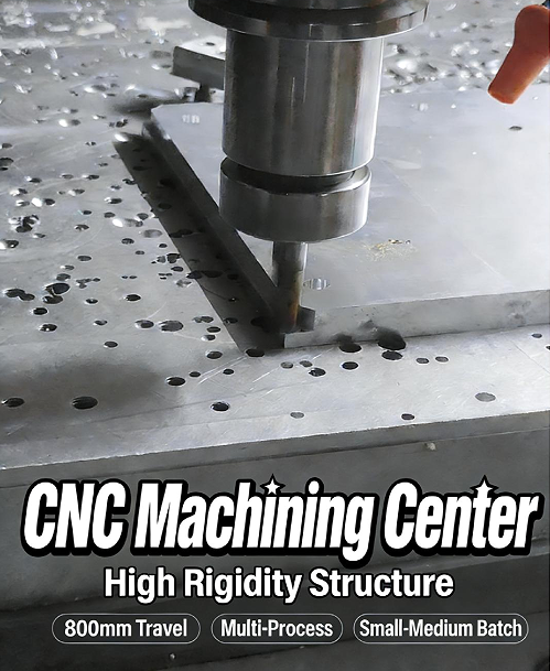
The LJ-855 vertical machining center is well suited to small mold part machining, with a travel range of about 800 × 500 × 500 mm, a spindle speed of 6000–12000 rpm, positioning accuracy of ±0.005 mm, repeatability of ±0.003 mm, a 24-tool magazine, and automatic tool change in about 1.5–2 seconds.
With simple FANUC programming, it can reliably handle milling, drilling, and tapping in one setup for stable batch production.
Small Mold Parts
Extreme Dimensional Tolerance
Small injection mold components used in smartphone camera modules are often only 3.5 mm long and 2.2 mm wide. To fit these tiny steel parts perfectly into the mold base slots, the machining tolerance allowed on the CNC machine is only ±0.0015 mm. A single human hair is roughly 0.06 to 0.08 mm thick.
After six hours of continuous cutting, the machine generates substantial heat, and the steel bed naturally begins to expand. If the temperature at the spindle head rises by just 2°C, the tool length can extend downward by 0.012 mm. The micron-level cutting depth originally set by the operator on the screen is gradually altered by temperature without anyone noticing.
· The chiller keeps the coolant circulating at 22.5°C.
· Cooling oil around the spindle removes 90% of the friction heat from the internal bearings.
· The three drive screws are hollowed at the center and filled with cooling oil to reduce temperature.
· The symmetrical left-right bed structure limits thermal deformation to within 0.002 mm.
Even after controlling thermal expansion and contraction, the micro end mill still faces enormous resistance when engraving hardened S136 mold steel. Using a flat end mill with a cutting diameter of only 0.2 mm to machine a 1.5 mm deep vent groove means the unsupported tool overhang reaches 7.5 times its diameter. The moment it hits HRC52 steel, a cutting depth of just 0.02 mm is enough to cause micron-level deflection in the ultra-fine shank.
If the tool tip retreats by only 0.003 mm, the sidewall of the vent groove is no longer perfectly vertical. When two tiny steel parts are assembled, a gap of 3 microns can remain—far too small to be seen by the naked eye. When molten plastic is injected into the mold cavity at 120 MPa, it can easily flash through that microscopic gap, leaving burrs all over the edge of the molded plastic part.
To suppress fine cutting vibration, the LJ-855 machining center uses P4-grade ultra-precision ceramic bearings inside the spindle. The machine can run up to 20,000 rpm for precision finishing of part contours. Instrument measurements keep spindle nose runout firmly below 0.0015 mm. The contact area between the tool holder and the spindle taper exceeds 85%, allowing micro-vibrations to dissipate through the heavy cast iron structure.
· Shrink-fit tool holders control runout to just 0.002 mm.
· Tool balance testing passes the 25,000 rpm standard.
· The laser tool setter delivers repeatability of 0.001 mm.
· Cooling water at 20–30 bar accurately flushes away tiny metal chips.
The motor drives the table, along with hundreds of kilograms of fixtures and workpieces, back and forth at high speed. When the feed rate reaches 8000 mm/min and the machine suddenly brakes and reverses direction, the balls inside the screw and the meshing surfaces of the transmission inevitably generate a slight reverse clearance and positional deviation.
A laser interferometer measures 21 points along the 800 mm travel of the table. It records the minute positional differences between forward and return movement. The operator fills the backend compensation table with correction values, forcing the original 0.008 mm positioning error back down to within the acceptable line of 0.002 mm.
Keeping the workshop at a constant 20°C is the basic environmental requirement for machining micron-level parts. Even a 0.5°C fluctuation from the air conditioning outlet can affect the size of a steel part. When the machine door is opened to change a 10 cm square fixture, a light draft passes over the surface, and an infrared thermometer shows a local temperature drop of 0.3°C on the metal casing.
Tiny impurities in the cutting fluid can easily ruin a micron-level machined surface. Metal debris as small as 50 microns can flow through the coolant lines. Even a single invisible particle trapped between the tool holder and the spindle taper can amplify tool tip runout to 0.005 mm during rotation, instantly scratching a 3-micron-deep groove across the smooth mold surface.
Surface Finish
Plastic plates used in hospital blood testing often contain densely packed grooves only 0.1 mm wide. Even the finest polishing wool brush cannot fit into such narrow channels. Workers are forced to use thin bamboo picks dipped in diamond paste and rub them by hand. The tiny inner right-angle corners of the plastic mold are immediately worn down by 0.005 mm.
The CNC machine must directly machine hardened steel at HRC54, scraping out a metal surface fine enough to reflect like a mirror. On an ordinary lathe, the machined surface always feels slightly rough to the touch—what the industry calls Ra0.8 roughness. But molds for miniature plastic parts require a surface finish approaching Ra0.1 or even Ra0.05.
The programmer draws extremely dense toolpaths on the computer so that adjacent cuts overlap very closely. A micro ball-end cutter with a tip radius of only 0.2 mm is used to reach tiny internal corners. Each time the tool advances laterally, its step-over is only 0.003 mm. Inside a narrow groove just 1 mm wide, the tiny tool tip must pass back and forth 333 times.
| Machined Area | Surface Finish Requirement | Micro Tool Used | Spindle Speed | Step-over per Pass |
| Optical lens curved surface | Mirror finish Ra0.05 | R0.1 mm ball cutter | 30,000 rpm | Only 0.001 mm |
| Sealing slider corner | Smooth finish Ra0.1 | R0.2 mm ball cutter | 24,000 rpm | Only 0.003 mm |
| Fine internal deep groove | Bright finish Ra0.2 | 0.3 mm flat end mill | 20,000 rpm | Only 0.005 mm |
| Ordinary insert sidewall | Flat finish Ra0.4 | 1.0 mm bull-nose cutter | 15,000 rpm | Only 0.015 mm |
The spindle of the LJ-855 must run above 24,000 rpm for fine finishing. At that speed, centrifugal force becomes extremely high. The spindle cartridge is packed with high-precision ceramic ball bearings, which hold lateral vibration during ultra-high-speed rotation firmly within 0.002 mm.
When fine-finishing a micro mold surface the size of a business card, the machine often has to run continuously for 12 hours. The cutting edge remains in constant hard contact with steel, and the cutting zone can reach several hundred degrees Celsius. The ultra-fine tool tip is coated with an AlTiN film only 2 microns thick, which withstands severe frictional heat and prevents the delicate edge from softening and dulling.
If a micron-level cutting edge becomes even slightly dull, it stops cutting cleanly and begins to press and rub the steel surface instead. The originally flat mold surface is then forced into a whitish work-hardened layer. Meanwhile, the spray nozzle beside it delivers atomized cutting fluid at pressures up to 30 bar.
Even if a single 0.01 mm chip is pulled back into the cutting zone by the high-speed rotating tool tip, it will immediately leave a small dent on the freshly machined mirror surface. That is where the seven-ton Meehanite cast iron base under the machine becomes critical. The table moves the steel block forward at a very slow and stable 500 mm/min.
Even the smallest vibration from the concrete floor can travel through the ground into the metal surface being machined. If a loaded forklift passes over a speed bump 50 meters away, the low-frequency vibration can silently travel through the earth and up into the machine. A barely perceptible tremor is enough to leave a transverse tool mark as thin as a hair on a Ra0.1 metal surface.
In a precision workshop, a 1-meter-deep pit is excavated where the machine will stand. The bottom is filled with crushed stone, and an isolated support platform is poured on top, completely separated from the surrounding floor. The loose gravel absorbs vibration transmitted from outside traffic. At the same time, the tool clamping interface at the spindle nose must not loosen even slightly.
Hard Mold Steel
A rough block of H13 hot-work mold steel has a hardness of only about HRC15 when first supplied. Workers load it into a heat-treatment furnace at 1030°C, then quench it rapidly in oil. The once-soft block that a band saw could cut easily immediately hardens to HRC52. If a standard HSS twist drill is used to drill it, white smoke rises, but no hole is made—instead, the drill tip is ground flat by 0.5 mm.
Workers can only switch to micro carbide milling cutters with hardness up to HRA90. Their ultra-fine cutting edges are coated with a 3-micron-thick AlTiN layer, allowing them to scrape directly against quenched steel that is harder than stone.
Using a micro end mill with a cutting diameter of 0.8 mm to machine a vent groove in HRC52 hardened steel is like trying to chisel granite with a sewing needle. The spindle of the LJ-855 drives this slender tool at 18,000 rpm. Each pass removes chips only 0.005 mm thick.
· If the programmed depth of cut is increased by just 0.02 mm, the 0.8 mm carbide shank snaps instantly.
· The huge resistance generated when cutting hardened steel can push the lateral load on the spindle nose up to 40 N.
· The temperature at the cutting edge can exceed 800°C within 0.1 second.
The original HRC52 surface layer is abused by heat and friction until its local hardness rises above HRC60. When the next finishing micro tool reaches this 0.02 mm-thick super-hardened layer, a fine alloy cutter costing RMB 200 can be worn out in less than 15 minutes.
The LJ-855 machining center counters high-frequency cutting vibration with its heavy base. The base and column are cast from FC300 high-grade gray iron, with dense cross-rib reinforcement throughout. This 5.5-ton iron structure absorbs the high-pitched squealing produced when tiny tools strike hardened steel. The spindle servo motor delivers 11 kW of torque, forcing the cutting edge through the hardened surface layer without hesitation.
When cutting hard material, the worst scenario is a machine base that flexes and vibrates. If the cast iron bed shakes by just 0.005 mm, the micro cutting edge starts bouncing on the steel surface, and the freshly machined bright finish is immediately dented with 3-micron pits.
In the system, the operator programs tens of thousands of tiny circles only 2 mm in diameter. The cutter moves forward while rotating like a helicopter blade, removing hardened steel with only a 0.05 mm side engagement each pass. The feed speed is pushed up to 1500 mm/min.
The very high lateral feed combined with the tiny depth of cut throws the glowing red chips out of the cutting zone instantly. Almost all of the heat is carried away by the chips before it can conduct into the mold steel.
· Cutting fluid is turned off, and instead compressed air at 0.5 MPa is aimed directly at the cutting point.
· A micro-lubrication flow of 50 ml per hour forms an ultra-thin oil film on the cutting edge.
· C-shaped fine chips leaving the cut at nearly 800°C cool rapidly to purple-black within 0.1 second.
To machine a hardened mold slider the size of a thumb, the roughing and finishing program may run through 100,000 lines of cutting code. After eight hours of constant steel-on-steel machining, the micro carbide tip inevitably wears shorter by 0.005 mm. The operator sets a system command so that every 60 minutes, the spindle automatically returns to the machine corner above the tool setter.
A non-contact laser emitter sends out a red beam only 0.001 mm thick. It measures the true physical length loss of the worn tool tip with high precision. Once the system detects that the tool has shortened by 0.003 mm, the control automatically commands the spindle to move down by another 0.003 mm to compensate perfectly for the wear.

Stable Output
Structural Rigidity
On the first day the LJ-855 arrives at the factory, the crane unloads it and the machine—occupying less than 6 square meters—goes onto the scale at a full 5.5 tons. The installers anchor it to a 200 mm-thick concrete foundation with six anchor bolts, each 24 mm in diameter. When roughing a mold base using a 50 mm face mill and taking a 3 mm deep cut, the cutting force indicator can instantly jump to 300 kg. If the machine base is not heavy enough, the entire machine will shudder the moment the tool meets the steel.
This hard impact travels back through the spindle and is absorbed by the HT300 Meehanite cast iron bed at the bottom. A special silicon-calcium alloy is added during iron smelting so that the graphite structure becomes extremely fine after cooling. Knock on the unpainted cast iron shell with a mold repair hammer, and the sound is dull, like striking solid wood. With tensile strength of 300 MPa, it withstands thousands of repeated impacts from the cutting edge every second.
· The base width has been extended to 1200 mm.
· Four roller linear guides are arranged in parallel beneath the Y-axis.
· Six extended guide blocks support an 800 kg worktable.
Looking upward from the base, the column supporting the spindle head is shaped like the Chinese character —narrow at the top and wide at the bottom. Measured with a tape, the base cross-sectional area is 40% larger than the top, forming a stable triangular structure. Traditional straight square columns tend to lean backward during rapid vertical movement of the spindle head. This A-shaped base holds Z-axis deflection during cutting within the 0.003 mm red line specified at the factory.
Inside the spindle head is an 11 kW AC servo motor paired with a BT40 spindle, for a total assembly weight of over 300 kg. The distance between the two Z-axis guideways has been widened by 30%, giving a spacing of 550 mm. The old style heavy counterweight has been eliminated and replaced by a nitrogen-charged balance cylinder, improving spindle head response by 0.2 seconds.
· The overhang from the spindle center to the Z-axis guideway is reduced to 150 mm.
· The Z-axis guideways are upgraded to larger No. 45 roller linear rails.
· The transmission screw diameter is increased from the common 32 mm to 40 mm.
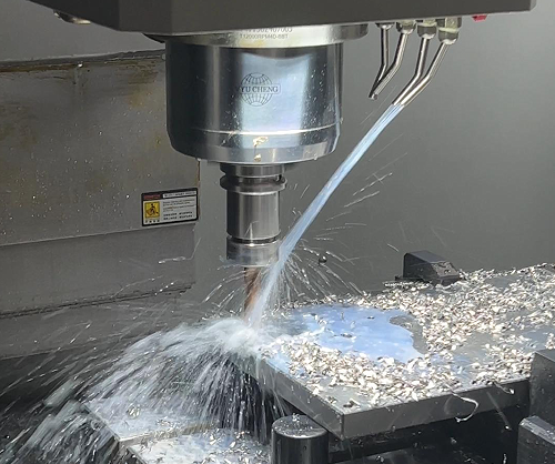
On the night shift, a machinist clamps a block of P20 pre-hardened mold steel in the vise; the hardness tester shows a reading of 30 HRC. The spring collet in the spindle firmly grips an imported carbide ball end mill with a cutting edge length of just 0.5 mm. The spindle is set to 8000 rpm, and the feed is entered at 1500 mm/min. The spindle load meter remains steady in the green zone at 45%. Cutting fluid at 20 kg pressure washes down over the cut, and the steel chips fall against the protective cover like heavy rain.
The cutting edge produces a deep, muted hiss as it works the steel, with no shrill squealing in the workshop. At complex corner-clearing areas, the tool tip must make repeated 90-degree turns. The machine saddle brakes from 48 m/min and reverses direction instantly. The 5.5-ton cast iron base and widened guideway support system absorb the inertia created by these sudden stops and starts.
· Laser interferometer measurement shows backlash of only 0.002 mm across all three axes.
· Circular interpolation testing gives roundness error below 0.004 mm.
· In emergency-stop tests with a fully loaded table, machine body movement stays below 0.01 mm.
A magnetic stand is placed on the table, with a dial indicator touching the side of the part. The pointer moves only slightly, showing a swing of just 0.001 mm. The quality inspector measures the thickness of the first 50 mold inserts with a digital caliper. On the CMM inspection report, the total variation between the largest and smallest measured sizes stays firmly at 0.004 mm. After 12 hours of continuous full-load cutting on the day shift, the spindle head temperature rises only 1.5°C above workshop ambient.
The high-speed reciprocating motion of the screw causes frictional heat, and metal naturally expands when heated. Before assembly, all X, Y, and Z ball screws of this machine are pre-stretched. P4-grade angular contact bearings are mounted at both ends, and the fastening nuts are tightened to elongate the screw by several microns. After machining hundreds of mold components during the day, the thermal expansion that occurs in the screws is almost exactly offset by this initial pre-stretch.
Thermal Deformation Control
In July, the machining workshop feels like a steam room, and by 2 p.m. the wall thermometer reads 35°C. A vertical machining center runs continuously for six hours with the spindle at 8000 rpm. The heat generated by the 11 kW motor flows downward through the metal housing. Touch the spindle cover with the back of your hand and it feels warm.
Hidden inside the machine base is a metal screw nearly one meter long. For every 1°C rise in workshop temperature, this steel screw expands by about 12 microns. But the dimensional allowance left on a mold insert for a mobile phone housing is only 5 microns in total.
This barely visible thermal expansion is enough to shift the carefully set tool position and ruin the dimensional result. To solve this, the LJ-855 uses a dedicated spindle oil cooler mounted outside the spindle head. The 1.5 HP compressor in the unit hums all day long.
Two black high-pressure oil hoses reinforced with steel mesh are connected into the spindle sleeve. Specialized VG10 cooling oil is pumped at 8 liters per minute through spiral channels along the inner sleeve wall.
A highly sensitive PT100 temperature sensor is connected to the oil cooler housing to monitor workshop temperature at all times. The control board keeps the circulating oil temperature within 2°C above ambient. As a result, thermal elongation in the spindle’s vertical motion is held firmly within 0.005 mm.
The two AC motors beneath the X-axis and Y-axis are major heat sources under full load. When the tool cuts deeper, motor housing temperatures often rise to around 60°C. To block that heat, the assembly workers insert a 15 mm-thick red Bakelite insulation plate between the motor flange and the cast iron base.
This insulation panel prevents heat from traveling into the machine structure. As a result, the cast iron base supporting the several-hundred-kilogram worktable remains stable and the guideways retain their factory straightness. When the operator mounts a dial indicator on the Y-axis housing and moves it back and forth 20 times, the pointer fluctuates by less than 0.002 mm.
· Ventilation grooves 12 mm wide are cut on both sides of the Y-axis ball screw nut seat.
· Six heat-dissipation ribs 30 mm deep are cast into the back of the spindle head.
· A Z-type belt separates the motor and spindle by 400 mm.
The inner side of the machine enclosure is lined with a full layer of 10 mm-thick black sound- and heat-insulating foam. High-temperature mist from the 15 kg cutting fluid spray hits the inside wall, but the heat does not transfer to the operator panel area outside. Using the same batch of S136 pre-hardened steel, the quality inspector records a 24-hour sampling report.
| Inspection Time | Workshop Temperature | Measured Y-axis Hole Distance | Dimensional Change |
| 08:30 | 26.5°C | 150.002 mm | Baseline |
| 14:30 | 34.2°C | 150.005 mm | Increased by 0.003 mm |
| 20:30 | 31.0°C | 150.004 mm | Increased by 0.002 mm |
| 02:30 | 25.8°C | 150.001 mm | Decreased by 0.001 mm |
Before the machine leaves the factory, four coin-sized temperature sensors are embedded in inconspicuous locations such as the base, column, and spindle box. Thin wires run back through plastic cable ducts into the control cabinet.
The FANUC 0i-MF Plus controller polls these four sensors every 2 milliseconds. If the system detects that the top of the column is 3.5°C warmer than the base, it sends an extremely small correction command to the Z-axis drive.
The motor receives a displacement command of less than 0.001 mm and lifts the tool by roughly half the thickness of a hair. The operator, staring at the screen, cannot even perceive these micro-adjustments happening hundreds of times per second.
As a result, the dimensions machined by the tool match the values on the drawing precisely. The machine’s 200-liter coolant tank is filled with white cutting fluid. A 2.2 kW high-pressure pump drives the coolant through flexible nozzles straight at the high-speed cutting edge.
At a flow rate of 30 liters per minute, more than half of the friction heat at the tool tip is removed instantly. The freshly cut metal chips are several hundred degrees hot and appear dark blue on the surface. Chip conveyors on both sides run at 12 rpm, carrying this hot waste away.
Less than three seconds after the hot chips drop into the metal trough, a spiral steel auger pushes them into the external scrap cart. The 5.5-ton cast iron machine bed is never significantly heated by this waste. The day-shift operator does not even need to stop the machine before handing it over to the night shift, which simply changes the workpiece and continues.
This saves the workshop staff from having to stop the machine every two hours to recheck bore diameters with a digital caliper. Even after 40 hours of uninterrupted machining, the final mold component measured in the temperature-controlled inspection room still falls within the acceptable 0.008 mm tolerance band.
Repeat Positioning Accuracy
A 40 mm-thick P20 steel plate requires 120 ejector pin through-holes, each 2.5 mm in diameter. After drilling each hole, the table moves 15 mm sideways to the next position. Once all 120 holes are drilled, the spindle returns to the origin, changes to a reamer, and travels back to the first hole for reaming. The positional deviation between the two stops is held firmly within ±0.003 mm.
At the rear of the X, Y, and Z axes are 3 kW AC servo motors. Each Yaskawa motor contains a 23-bit absolute encoder. For every full revolution of the motor shaft, the encoder generates 8,388,608 electrical pulses. The control board reads these ultra-high-frequency signals and divides each 16 mm screw pitch into millions of movement increments.
Once the G00 rapid traverse command is executed, the 800 kg cast iron worktable accelerates to 48 meters per minute. In the final 0.1 second before reaching the programmed coordinate, the motor brakes sharply and stops exactly at the specified position.
In the factory test room, technicians set up a Renishaw laser interferometer for final calibration. The laser beam reflects off a mirror fixed to the worktable. The table moves forward 300 mm, stops, and then returns to the origin. The green trace on the interferometer screen fluctuates slightly before settling at 0.002 mm. The operator repeats the exact same movement 30 times.
A factory-measured screw pitch compensation table is stored in the machine’s control chip. Each time the table moves 10 mm, the system quietly sends an additional command to the motor to move slightly more or slightly less by a few microns. More than 200 groups of micro-correction data are stored in memory, and the controller reads thousands of compensation values per second and feeds them to the drive.
Power is transmitted to the screw through a 45 mm jaw coupling. At the center of the aluminum alloy coupling is a red polyurethane elastic insert. During assembly, the workers tighten the locking screws at both ends to the specified torque of 12 N·m. When the motor reverses direction, the coupling grips the screw joint so tightly that even 1 micron of play is eliminated.
· The transmission screw uses C3-grade ground machining, with thread raceway tolerance held to 0.005 mm.
· The double-nut preloaded screw structure compresses the internal balls tightly and removes bidirectional backlash.
· The Z-axis brake motor reacts in less than 20 milliseconds when power is cut, preventing the spindle head from dropping.
On the side of the machine is a disc-type tool magazine holding 24 alloy cutters of various lengths. After finishing one cavity, the spindle rises quickly to avoid the workpiece and stops at the tool change position at the top of the Z-axis. The mechanical arm removes the used tool and loads a new 8 mm flat end mill. The entire sequence—from grabbing the tool to clamping it—takes just 1.8 seconds.
Before leaving the factory, the tool changer cylinder undergoes 1 million consecutive tool change tests without jamming. The four-jaw gripper inside the spindle drawbar maintains a clamping force of 800 kg on the retention knob every time.
On the night shift, the inspector places a dial indicator on the newly changed tool tip and checks height variation. After ten consecutive tool changes, the pointer movement stays completely within a 0.004 mm range. Invisible fine iron dust inside the spindle taper is blown out instantly by a 5 kg central air blast from above. The contact area between the tool holder taper and the spindle taper remains above the 85% standard.
When the cavity bottom requires a final finishing pass, the programmed depth of cut is only 0.02 mm. The 0.004 mm variation shown on the dial indicator is less than half the thickness of a hair. At 8000 rpm, the resulting steel cavity floor is flat and bright.
Easy Setup
Easy to Adjust
The front sheet-metal door of the LJ-855 opens to a width of 850 mm, and the distance from the spindle center to the rear guideway is 520 mm. When lifting a P20 mold steel block measuring 150 mm square and weighing 10 kg onto the table, the operator reaches forward 12 cm less, which makes a full day of work less tiring on the waist.
The worktable surface sits exactly 800 mm above the floor, well suited to people between 1.65 and 1.75 meters tall. Holding a 1.5 kg pneumatic wrench to tighten an M12 bolt, the operator’s arm naturally forms a 90-degree angle, allowing torque to settle steadily at 45 N·m.
After machining H13 mold steel, the table is covered with chips, and a new workpiece can easily sit unevenly if it is loaded directly. A high-pressure water gun mounted beside the machine, operating at 1.5 MPa, flushes chips away in just 15 seconds, working together with the augers on both sides to push the debris into the 150-liter rear coolant tank.
Cleaning the fixture base is simple: just grab the external air gun. At 0.6 MPa, the nozzle with a 120 mm tube can reach into holes and blow water completely dry, keeping the gap beneath the blank under 0.002 mm when it is loaded.
Tool loading takes effort. The machine is equipped with a 24-tool disc magazine and a BT40 spindle.
· A single BT40 holder with cutter weighs about 2.5 kg.
· The unclamp button is only 300 mm from the spindle head.
· Support the tool with the left hand, press the button with the right, and one tool is mounted in 2 seconds.
· The housing is made of transparent acrylic, so positions 1 through 24 can be counted at a glance.
The screen panel uses a damped hinge and can rotate 270 degrees. The operator holds a magnetic handwheel in the left hand, snaps it onto the machine body, stares at the dial indicator, and slowly turns the wheel with the right hand.
The handwheel has X1, X10, and X100 feed multipliers. Each click moves the spindle by 0.001 mm, 0.01 mm, or 0.1 mm. When locating the starting point for a 3 mm wide groove, the operator can inch into position without overshooting.
When milling deep mold cavities, cutting fluid must be aimed accurately. Four adjustable coolant nozzles surround the spindle nose. Insert an Allen key into the brass nozzle and adjust it slightly to align the spray.
All four coolant streams converge 5 mm below the tool tip. The flushing is even, chips do not collect on one side, and there is no need to stop midway and open the door to remove swarf. Even when the spindle speed reaches 8000 rpm, the cutter still does not overheat.
When test-cutting the first part, crashes are a concern. The control panel has a handwheel simulation button. Once it is pressed, the programmed speed no longer matters, and feed motion depends entirely on how fast the handwheel is turned.
One full turn of the handwheel lowers a 12 mm flat end mill by 2 mm. If the operator notices the tool is about to hit the clamp plate, a reverse turn immediately retracts the spindle along the same path—without changing the machine code at all.
3D surface programs generated from mold drawings are often large, and files of several megabytes must be transferred into the machine.
· The USB port on the panel has a dust cover and supports hot plugging.
· The machine’s built-in Ethernet port can run at 100 Mbps.
· Memory has been expanded to 2 MB, enough to store multiple finishing programs.
· If power fails, pressing the spindle recovery button returns the tool to the position where it stopped.
The 2-liter oil pump automatically builds pressure to 15 kgf. P-grade roller guideways and C3-grade screws on the X, Y, and Z axes are fully lubricated with VG68 guide oil in 5 seconds.
If the spindle has been idle overnight, it automatically runs a 15-minute warm-up cycle. Speed gradually rises from 500 rpm to 6000 rpm. The machine temperature increases by less than 10°C, and thermal elongation of the Z-axis stays within 0.012 mm, so the operator does not have to stand by waiting for it to idle.
A standard machine vise is commonly used for mold inserts. A 160 mm wide vise has two 18 mm locating keys underneath. The T-slots on the table are ground to H7 tolerance, so when the vise is pushed fully into place, jaw alignment error is under 0.01 mm.
In the past, operators had to sweep the 150 mm jaw face three times with a dial indicator to align it. Now they simply use a No. 18 box wrench to tighten two M16 nuts, completing the entire setup in 20 seconds.
The probe must be calibrated every week, and the button is located in the system menu. A 25.000 mm ceramic calibration sphere is mounted at the upper-right corner of the table. Calling up program O9801, the probe touches four points on the sphere at 50 mm/min.
The runout error of the ruby stylus ball is automatically written into the table, and eccentricity error is held below 0.002 mm.
The 10.4-inch color screen is divided into three boxes for absolute position, machine position, and remaining travel. The text and keys are enlarged, so even from 1.5 meters away, the operator can clearly see that the X-axis has reached position 235.125.
The soft-limit parameters are locked in the background. A crash-protection line is set 120 mm from the spindle nose. Once the spindle descends to this protective line, the system immediately triggers a Z-axis emergency stop alarm and cuts motor power.
Workshop lighting is often poor, making calipers difficult to read. Two rows of 24 V explosion-proof LED lights are installed on top of the machine, with waterproof and oilproof protection rated at IP67. Their light output of 1200 lumens brightly illuminates the 1000 mm-long worktable.
When installing a tiny 0.5 mm drill, the light on the tip shows no shadowing. The operator can clearly see whether the cutting edge is chipped or whether chips are stuck on it, saving a great deal of trouble over an 8-hour shift.
System Design
The 10.4-inch screen of the FANUC 0i-MF Plus system is covered with a 3 mm-thick scratch-resistant, oil-resistant film. Even when wearing nitrile gloves covered in cutting fluid, the operator can press the soft keys beside the screen and get a response within 0.1 second. The panel buttons use 15 mm square micro-switches rated for 1 million actuations.
Oil mist is always present in the workshop, and keyboard gaps are the easiest place for dirt to enter. The LJ-855 key panel is fully sealed to IP65. The physical spacing between buttons has been increased to 4 mm, so operators wearing thick gloves can input G-code by touch without accidentally hitting neighboring keys.
On older machines, finding the tool setting page often means digging through five layers of menus. The LJ-855 places work coordinate setting and tool compensation directly on four fixed shortcut buttons beneath the screen. A couple of quick presses instantly brings up the offset tables for G54 through G59.
When entering tool length compensation, it is easy to misread a decimal point and cause an accident. The system comes preloaded with an automatic calculation macro. Once the tool tip touches the tool setter, the Z-axis machine coordinate displayed on the screen is copied directly into the corresponding H compensation field. This eliminates the need for the operator to subtract the machine zero manually on a calculator.
Mold ejector plates often require a ring of cooling holes. Writing dozens of X and Y coordinate positions by hand is time-consuming. The system includes the G68 coordinate rotation function. The operator only needs to input a center hole at X100. Y100 and add an angle of R45., and the spindle automatically calculates the coordinates for the remaining eight holes around that center.
When machining tiny mold electrodes, the 3D toolpath consists of many irregular short line segments. With G05.1 Q1 high-precision contour control enabled, the processor reads 200 blocks ahead. When it encounters a sharp corner, the servo motor preemptively slows the feed rate from 2000 mm/min to 800 mm/min.
The usability of a control system is most obvious in the number of steps needed each morning when changing to a new part.
| Operation | Old System Steps | LJ-855 System Steps | Time Saved |
| Set work coordinate origin | Edge finding by hand, mental calculation, manual input of 6-digit coordinates | Probe edge-finding with one-click automatic input to the parameter table | 4 min 30 sec |
| Measure tool length | Use feeler gauge, read scale, manually enter decimals with care | Run macro program for automatic sensing and H-value entry | 3 min 15 sec |
| Load mold program | Connect laptop through RS232 serial cable for 30-minute transfer | Insert USB drive and load an 8 MB machining file in 3 seconds | 29 minutes |
| Set drilling cycle | Write G0/G1 drill and retract code line by line | Enter G83 peck drilling parameters with 3 mm per peck | 8 minutes |
If air pressure drops below 0.4 MPa, the machine spindle cannot hold the BT40 tool holder tightly. Instead of only displaying a dry error code like “EX1001,” the alarm column shows a plain-language Chinese message: “Air supply pressure below 0.5 MPa. Please check the main air compressor valve in the workshop.”
If a power failure occurs halfway through a tool change and the tool magazine is stuck mid-position, there is no need to call maintenance to modify K parameters in the background. The panel includes a tool magazine recovery menu. Following the screen prompts—“Spindle Orient,” “Tool Pot Up,” and “Magazine Reverse”—the operator can restore the magazine to Tool No. 1 in two and a half minutes.
In the past, transferring several megabytes of machining code required a 5-meter RS232 cable across the workshop. The LJ-855 panel now includes a CF card slot and two USB 2.0 ports. Insert a 16 GB industrial USB drive, and an 8 MB finishing program for a freeform surface can be copied into memory in 3 seconds.
To prevent data loss during power failure, the system motherboard memory has been expanded from the conventional 512 KB to 2 MB. The roughing, semi-finishing, and finishing programs for a medium-sized mold can all be stored in the machine at once. During unattended night-shift machining, no one needs to remain next to the machine to swap USB drives.
In deep mold cavities where cutting load is heavy, a 10 mm end mill can snap from overload. The system includes spindle load monitoring software. Once the upper load limit is preset at 85%, any spike to 86% automatically forces the feed axis to cut the feed speed in half.
Because the workshop runs three shifts, the next operator may not know where the previous shift stopped. The system provides a runtime statistics screen. It clearly shows that rapid movement G00 accounted for 15%, and cutting feed G01 accounted for 80%. It also records that 42 small inserts were machined that day, each taking 18 minutes and 45 seconds.
High Precision Requirements
When the crane lowers the 5.5-ton machine base onto the floor, the LJ-855 reveals one of its key advantages: it is made from HT300 aged cast iron, and the casting is left outdoors for six full months after pouring.
Six adjustable leveling pads are placed beneath the machine base. The installer places a level on the worktable and slowly adjusts the threaded supports with a wrench. Across a 1 meter by 1 meter area, height difference is held tightly within 0.01 mm.
When machining quenched parts at HRC52, the heavy cast iron absorbs all the vibration generated by the tool biting into the hardened material, so the resulting surface still comes out flat.
In mold making, deep and narrow cavities are common. An extension bar is mounted on the spindle nose and reaches 150 mm down into the steel block. Inside it are four P4-grade ceramic ball bearings. At a full 8000 rpm, measured tool tip runout remains below 0.002 mm.
The table moves several hundred kilograms of steel workpieces in all directions, driven by ball screws underneath. The X, Y, and Z axes all use C3-grade screws with a 12 mm pitch.
During assembly, nuts at both ends apply pre-stretch to the screw. After 10 hours of continuous operation, thermal elongation is minimized, and the 0.005 mm positioning accuracy is maintained.
To ensure accurate travel, every machine must pass laser interferometer calibration before leaving the factory.
· The laser probe is aimed at a reflector and measures one full pass along a 1000 mm travel.
· Actual stop positions are checked every 10 mm.
· The system calculates the errors and writes compensation data into the CNC parameter table.
· Even if the screw has a manufacturing tolerance of two or three microns, the control automatically corrects it.
When the temperature difference between morning and afternoon in the workshop swings from 15°C to 30°C, three temperature sensors mounted inside the machine column report the temperature to the main board every minute.
Following the law of thermal expansion and contraction, the system instructs the Z-axis to rise by a few microns. After a full day of work, a cavity cut to 20.005 mm in the morning is still 20.005 mm in the afternoon.
When machining mold ejector pin holes, even an error as small as the thickness of a hair can cause flashing on the final plastic part.
For a through-hole 40 mm deep in a mold, the drawing may specify an H7 tolerance. The tool magazine loads an internally cooled carbide drill. High-pressure water at 2 MPa exits through the two fine holes inside the drill and flushes chips out from the bottom of the hole.
After drilling, the machine switches to a 5.98 mm reamer and feeds slowly in and out. A plug gauge confirms the result: the 6.000 mm go gauge slides in smoothly, while the 6.005 mm no-go gauge will not enter, proving the hole diameter is well controlled.
The mating surfaces of a mold must fit tightly. A 50 mm face mill is used to skim the base surface. The spindle depth of cut is set at 0.05 mm and the feed rate at 800 mm/min.
Steel chips peel away in sheets, and the machined plate surface feels smooth to the touch, reaching Ra0.4. The polishing worker only needs a few quick passes with 320-grit sandpaper before the part is ready.
When an end mill interpolates a large circular hole, the follow-up performance of the motors becomes critical. For a 60 mm diameter circle, the X and Y servo motors must constantly reverse direction and redistribute force.
The servo refresh cycle of the FANUC system is set below 0.1 milliseconds. The encoder outputs 1 million pulses per revolution. The motor immediately fine-tunes the current as it receives each signal, and the resulting roundness error, checked on a roundness tester, stays within 0.004 mm.
Cutting steel generates several hundred degrees of heat, and thermal elongation of the spindle can cause inconsistent Z-axis depth. The LJ-855 spindle is surrounded by a cooling water jacket.
A dedicated 1.5 kW chiller is installed in the corner of the workshop. Chilled water flows through the system at 15 liters per minute, holding spindle temperature firmly at 25°C. After 8 hours of continuous machining, spindle thermal elongation measures less than 0.012 mm, and there is no step difference where the toolpath connects.
When machining 3D surfaces, the X, Y, and Z axes must move together in coordinated arcs. The system’s nano-level interpolation function becomes essential here. The ball end mill moves step by step in increments of 0.001 mm.
The finished 3D surface shows no visible tool marks. When the upper and lower mold halves are brought together and a flashlight is shone from behind, not even the slightest light gap can be seen from the front.