

When machining a deep, narrow slot in mold steel, tool breakage usually comes down to three things: too much unsupported tool length, too much cutter engagement, or chips trapped in the slot. Keep the tool as short as the job allows. A 6 mm cutter with 24 mm of unsupported reach is 4D. Push that same cutter out to 36 mm and it becomes 6D, which is much harder to keep stable.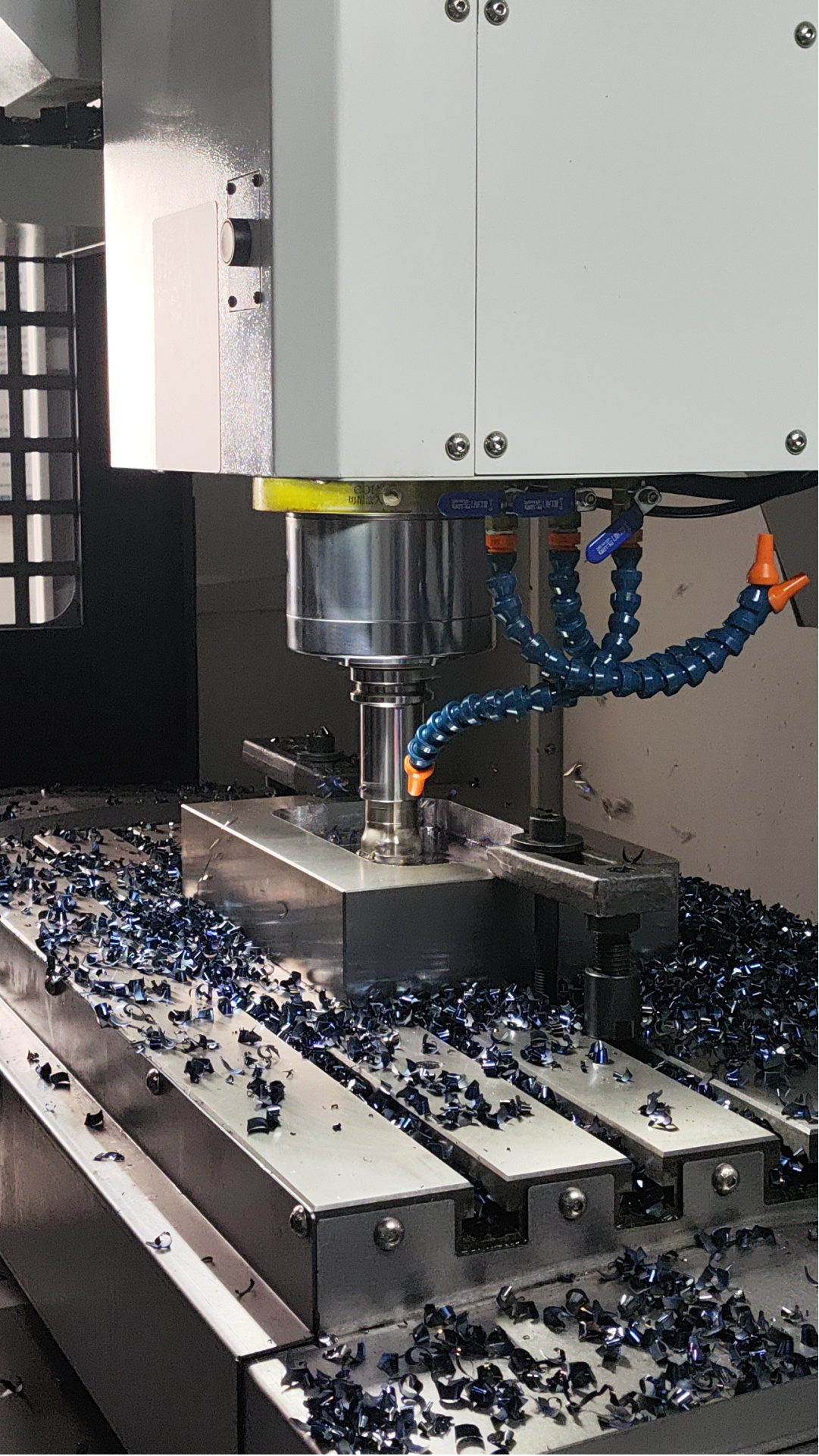
Check the Slot Before Choosing a Tool
Before picking the cutter, write down the dimensions and material conditions that actually affect the cut:
- Slot width
- Slot depth
- Bottom and end-corner radius
- Steel grade
- Actual hardness
- Required width tolerance
- Whether the slot is blind, open-ended, or through
- Required tool reach
Do not judge the job by slot depth alone. A 50 mm-deep slot does not automatically need 50 mm of unsupported cutter. You may be able to remove the first 20 mm with a short tool and save the long cutter for the lower section.
Reach ratio = unsupported tool length ÷ cutter diameter
| Cutter | Unsupported Reach | Reach Ratio |
|---|---|---|
| 10 mm | 20 mm | 2D |
| 8 mm | 32 mm | 4D |
| 6 mm | 36 mm | 6D |
| 6 mm | 42 mm | 7D |
| Reach Ratio | What to Check |
|---|---|
| Below 3D | Runout, workholding, and chip removal |
| 3D–5D | Deflection, chatter, radial engagement, and chip evacuation |
| 5D–7D | Keep heavy full-width cutting to a minimum and consider staged machining |
| Above 7D | Compare long-reach tooling, plunge roughing, predrilling, or EDM |
These ranges are for process planning, not hard tool limits. NIST testing on long, slender end mills shows that tool length and the complete machine-tool system affect deflection and milling stability.[1]
Small Changes in Stickout Matter
A long cutter behaves a bit like a long lever. In a simple cantilever model, bending rises quickly as unsupported length increases.[2]
If everything except length stays the same:
| Length Change | Relative Theoretical Deflection |
|---|---|
| 40 mm → 45 mm | (45 ÷ 40)³ ≈ 1.42× |
| 40 mm → 50 mm | (50 ÷ 40)³ ≈ 1.95× |
| 40 mm → 60 mm | (60 ÷ 40)³ ≈ 3.38× |
A real end mill will not follow these numbers exactly because the holder, spindle, cutting forces, and tool geometry all affect the result. The calculation still makes one thing clear: a few extra millimeters of stickout can matter a lot.
For a necked cutter, check the neck diameter and flute-core diameter as well as the nominal cutting diameter. An 8 mm cutter with a 5 mm neck will not have the same stiffness as a solid 8 mm section over the same length.
Choose the Largest Cutter That Still Leaves Room
A cutter that almost matches the slot width leaves very little room for the CAM path to reduce radial engagement.
| Slot Width | Cutter | Width Ratio |
|---|---|---|
| 16 mm | 16 mm | 1.00 |
| 16 mm | 10 mm | 1.60 |
| 12 mm | 8 mm | 1.50 |
| 10 mm | 8 mm | 1.25 |
| 8 mm | 6 mm | 1.33 |
A 10 mm cutter inside a 16 mm slot leaves 6 mm of extra width. A 16 mm cutter leaves almost nothing. With the 10 mm tool, CAM has room to move the cutter away from the wall and control engagement.
Going smaller is not always better. A small cutter gives more side clearance, but it also bends more easily. In most cases, use the largest diameter that still leaves enough room for the toolpath you want to run.
The cutter also has to suit the steel grade, hardness, coating, and cutting method. ASIATOOLS covers these points in its guide to choosing cutting tools for mold steel.
Use Short Flutes and Enough Reach
A 50 mm-deep slot does not need 50 mm of flute length.
If each roughing level removes only 6 mm axially, a cutter with 8–10 mm of flute and a relieved neck may work better than one with 40 mm of full flute length. Extra flute length removes material from the tool core, which can reduce stiffness.
Keep these dimensions separate when checking a cutter drawing:
- Flute length: the section with cutting edges
- Neck length: the relieved section behind the flutes
- Reach: how far the cutting end can reach without interference
- Stickout: the unsupported tool length outside the holder
Use the largest neck and core size that will still clear the slot wall.
Do not leave only a few hundredths of a millimeter between the neck and the CAD wall. If clearance is only 0.03–0.05 mm, a small amount of cutter bending may make the neck rub. Simulate the neck, shoulder, holder, and remaining finish stock together.
Keep Stickout to the Minimum
Set stickout after checking the complete tool and holder assembly in CAM.
- Holder to workpiece top
- Holder to slot wall
- Spindle nose to workpiece
- Tool shoulder to workpiece
- Tool neck to slot wall
If 34 mm of stickout already gives 3 mm of safe holder clearance, there is no reason to set the tool at 50 mm. That would add 16 mm of unsupported length without giving the cutter any extra access.
NIST research has also shown that changing tool overhang changes the vibration behavior of the tool-holder-spindle system.[3]
Measure Runout Before Changing Cutting Data
Measure TIR with the cutter installed in the holder that will actually run the job. Measure as close to the cutting section as practical.
Runout becomes especially noticeable when feed per tooth is small.
| TIR | Feed per Tooth | TIR Compared With fz |
|---|---|---|
| 0.003 mm | 0.030 mm/tooth | 10% |
| 0.003 mm | 0.010 mm/tooth | 30% |
| 0.005 mm | 0.020 mm/tooth | 25% |
| 0.010 mm | 0.020 mm/tooth | 50% |
These percentages are not acceptance limits. They show how large the runout is compared with the programmed chip load.
Once runout becomes a large part of the chip load, the flutes may stop sharing the cut evenly. One edge can end up doing most of the work and chip long before the others.
If TIR is higher than expected, clean and inspect:
- Cutter shank
- Collet or holder bore
- Spindle taper
- Holder contact surfaces
- Clamping condition
Fix the mechanical problem first. Cutting the feed just to make the machine sound quieter can hide the real cause.
Choose the Cutting Method From the Slot
| Condition | Process to Consider |
|---|---|
| Cutter has useful side clearance | Dynamic or adaptive milling |
| Cutter almost fills the slot | Controlled slotting with smaller axial depth |
| Long reach causes side deflection | Plunge roughing |
| Entry into solid steel is difficult | Predrilling, ramping, or helical entry |
| Long reach, hard steel, sharp corners | Compare EDM |
A path that works in a 16 mm-wide slot may be a bad choice in an 8 mm-wide slot. Cutter clearance changes how much radial engagement you can actually control.
Use Dynamic Milling When There Is Room
In full-width cutting:
ae ≈ 100% of cutter diameter
Here, ae is radial engagement.
If the cutter is smaller than the slot, CAM can keep ae much lower. A 10 mm cutter inside a 16 mm slot has room for the cutter center to move sideways. A 16 mm cutter in that same slot does not.
Do not judge the path only by the average feed rate. Check whether engagement stays controlled through the whole move.
- Entry
- Closed slot ends
- Internal corners
- Rest-material areas
- Cleanup passes
- Re-entry after retract
- Tool-change positions
A program might run smoothly for 95 mm of a 100 mm slot, then bury the cutter during the last 5 mm cleanup move. That short section can be enough to break the tool.
Use Full-Slot Cutting Differently
An 8 mm cutter in an 8 mm slot is already cutting at almost 100% radial engagement. You cannot reduce ae unless you change the cutter diameter or use another machining strategy.
In that situation:
- Start from the cutter maker's slotting data
- Reduce axial depth of cut, or ap, if needed
- Use the correct slotting feed per tooth
- Keep chips out of the slot
- Do not leave a heavy cleanup cut at the closed end
With an 8 mm cutter taking a full-width cut:
| ap | Cross-Section Removed per Pass |
|---|---|
| 4 mm | 8 × 4 = 32 mm² |
| 3 mm | 8 × 3 = 24 mm² |
| 2 mm | 8 × 2 = 16 mm² |
Dropping ap from 4 mm to 2 mm cuts the nominal cross-section from 32 mm² to 16 mm². The correct ap still depends on the cutter, steel, reach, and machine, but axial depth becomes one of the main controls when radial engagement cannot be reduced.
When setting CNC roughing parameters for mold steel, check ae and ap together with cutting speed and feed instead of changing one number on its own.
Predrill When Entry Is the Problem
A long end mill does not have to make its own entry hole. If the drawing gives you room, drilling the entry first can take a lot of stress off the cutter.
- Slot width: 8 mm
- End mill: 6 mm
- Slot depth: 35 mm
A drilled hole slightly larger than 6 mm lets the end mill start with side cutting instead of forcing its center into solid steel.
You can also drill several holes along a narrow slot before milling. Three 6.5 mm holes, for instance, remove part of the center material before the end mill starts its long-reach work.
Check what material remains between the holes. Thick webs can hit the cutter like small steps, so do not run into them at full programmed feed without checking the path first.
Use Plunge Roughing for Long-Reach Cuts
Plunge roughing removes material mainly through axial moves instead of asking a long cutter to push sideways through the full slot.
Consider it when:
- The slot is too narrow for a useful dynamic path
- The required reach is long
- Full-width side cutting chatters
- The selected cutter is designed to plunge
If a 6 mm cutter needs 40 mm of reach:
40 ÷ 6 = 6.67D
At that reach, side cutting may become unstable. Plunge roughing can remove most of the material first, leaving only a lighter side cut for cleanup and finishing.
Follow the cutter maker's limit for plunge depth and step between plunges. A center-cutting end mill is not automatically suitable for heavy plunge roughing.
Plan Entry and Tool Changes
Enter with a helix, ramp, predrilled hole, or open end whenever the geometry allows it. Avoid straight plunging into solid steel unless the cutter is designed for that job.
A 48 mm-deep slot could be split like this:
| Tool | Working Depth |
|---|---|
| Short cutter | 0–18 mm |
| Medium-reach cutter | 15–32 mm |
| Long-reach cutter | 29–48 mm |
The 3 mm overlaps are only an example. They give the next cutter an already opened area instead of making it hit an untouched shoulder at full depth.
Another 45 mm slot might use 0–16 mm, 13–30 mm, and 27–45 mm. The exact depths depend on the cutters, holder clearance, and slot geometry.
Get Chips Out of the Slot
Even good cutting data will not save a cutter that is chewing through its own chips.
When chips collect at the bottom, the cutting edge hits fresh steel and loose chips at the same time. That raises edge load and can leave scratches down the slot wall.
On a first-off part, check the slot after roughly the first 10–15 mm of depth and again when the long-reach cutter starts the lower section. Adjust the timing to the actual job.
Look for:
- A bed of chips following the cutter
- Packed material inside the flutes
- Scratches on the lower wall
- Chips trapped at a blind end
Ways to improve chip removal include:
- Through-spindle coolant
- Through-tool coolant where available
- Directed external coolant
- Air aimed into the slot opening
- Automated chip clearing
With an open-ended slot, try to move chips toward the opening. With a blind slot, pay extra attention to the bottom and closed end. For a through-slot, check that the fixture is not blocking the lower outlet.
A CNC chip blower can clear chips around the machining area, but the air still has to reach the slot. Blowing across the top of the table will not help much if chips are packed 40 mm down.
For manual compressed-air cleaning in U.S. workplaces, OSHA requires cleaning air to be below 30 psi and used with effective chip guarding and personal protective equipment.[4]
OSHA also requires guarding against hazards such as rotating parts and flying chips around machinery.[5]
Check Whether the Machine Can Run the CAM Path
Dynamic milling often uses many short arcs and quick direction changes. The feed written in the program is not always the feed the machine reaches at the tool tip.
- Programmed feed: 1,000 mm/min
- Actual feed on longer straight moves: 950–1,000 mm/min
- Actual feed through small arcs: 300–450 mm/min
If the machine keeps dropping from around 1,000 mm/min to 300–450 mm/min through small arcs, the real chip load and cutting action will not match what you saw on the CAM screen.
Watch:
- Actual feed through small arcs
- Axis acceleration
- Controller look-ahead
- Spindle torque at the selected RPM
- Machine rigidity
- Spindle condition
If the control cannot follow the path smoothly, try larger path radii, smoother links, fewer tiny segments, or a simpler toolpath.
When comparing a vertical machining center for deep-slot work, do not look at spindle RPM alone. Controller behavior, spindle condition, rigidity, and chip removal can matter just as much.
Calculate RPM From Cutting Speed
Use the cutter maker's cutting-speed range for the exact tool, steel grade, hardness, coating, and cutting method.
For metric units:
RPM = Vc × 1000 ÷ (π × D)
| Cutter | Example Vc | Calculated RPM |
|---|---|---|
| 6 mm | 100 m/min | ≈ 5,305 rpm |
| 8 mm | 100 m/min | ≈ 3,979 rpm |
| 10 mm | 120 m/min | ≈ 3,820 rpm |
| 12 mm | 120 m/min | ≈ 3,183 rpm |
The Vc values in this table are calculation examples, not universal settings. Use the value specified for your cutter and material.
For the 10 mm example:
RPM = 120 × 1000 ÷ (3.1416 × 10) ≈ 3,820 rpm
Calculate Feed From Feed per Tooth
Feed = RPM × number of flutes × fz
| RPM | Flutes | fz | Calculated Feed |
|---|---|---|---|
| 3,800 | 4 | 0.020 mm | 304 mm/min |
| 3,800 | 4 | 0.025 mm | 380 mm/min |
| 4,000 | 4 | 0.025 mm | 400 mm/min |
| 4,000 | 5 | 0.025 mm | 500 mm/min |
With a four-flute cutter at 3,800 rpm and 0.025 mm/tooth:
3,800 × 4 × 0.025 = 380 mm/min
Run this calculation before machining. A wrong flute count or misplaced decimal in CAM is easy to miss on the screen and much harder to ignore after a tool breaks.
Low-radial-engagement milling may also need chip-thinning compensation. Use the cutter maker's data or a CAM calculation for that tool instead of copying a multiplier from another cutter family.
Do Not Fix Chatter With Feed Override Alone
If chatter starts, check the setup in this order:
- Shorten stickout where possible
- Check radial engagement
- Clear chips
- Measure runout
- Check axial depth
- Check for neck or holder rubbing
- Try another spindle speed
- Recalculate feed
Changing spindle speed can move the cut away from an unstable vibration range, but there is no fixed 10% or 20% adjustment that works on every machine. NIST research shows that milling stability changes with spindle speed, tool length, and the dynamics of the complete system.[6]
If you want to keep the same feed per revolution:
- 4,000 rpm at 400 mm/min = 0.10 mm/rev
- 3,600 rpm × 0.10 = 360 mm/min
- 3,400 rpm × 0.10 = 340 mm/min
If you change RPM, recalculate feed. Otherwise the chip load changes with it.
Leave Stock for Finishing
Do not rough a deep slot straight to finished width with a long, flexible cutter.
For a medium-size mold slot, 0.10–0.30 mm per wall is a reasonable trial range before inspection. The final allowance should come from the tool, reach, material, roughing accuracy, and finish requirement.
| Trial Wall Stock | When It May Make Sense |
|---|---|
| 0.10 mm | Stable roughing with little measured taper |
| 0.15 mm | Moderate slot depth and predictable roughing |
| 0.20 mm | Longer reach or visible roughing error |
| 0.30 mm | Higher uncertainty, as long as the finishing cutter can handle the stock |
The finishing cutter has to remove what is physically left in the slot, not just the allowance shown in CAM.
Suppose CAM is set to leave:
0.05 mm per wall
Tool deflection leaves another:
0.06 mm per wall
near the bottom.
The actual finish stock is then:
0.05 + 0.06 = 0.11 mm per wall
Measure the rough slot before deciding how much the finishing cutter really has to remove.
Measure the Top, Middle, and Bottom
A slot can measure correctly at the opening and still be narrow at the bottom.
For a 50 mm-deep slot, you could inspect around these depths:
- Top: about 5 mm below the opening
- Middle: about 25 mm deep
- Bottom: about 45 mm deep
Suppose the target width is 12.00 mm:
| Position | Measured Width |
|---|---|
| Top | 12.02 mm |
| Middle | 11.96 mm |
| Bottom | 11.88 mm |
The top-to-bottom difference is:
12.02 − 11.88 = 0.14 mm
That pattern is not a simple constant offset. Check cutter bending, chip buildup, remaining stock, and tool reach before changing compensation.
If the readings are 11.94, 11.95, and 11.94 mm instead, the error is almost the same at every depth. In that case, tool diameter, wear compensation, or the measurement method moves higher on the checklist.
Read the Tool Damage
| What You See | Check First |
|---|---|
| One flute has much more damage | Runout and holder condition |
| All corners chipped | ae, ap, and entry load |
| Flutes packed with chips | Chip evacuation |
| Chatter marks on the wall | Stickout, RPM, and engagement |
| Damage starts near the bottom | Chip packing, long reach, or rubbing |
| Slot becomes narrower with depth | Tool bending |
| Repeated failure at the slot end | CAM engagement at the closed end |
If three cutters all begin to chip around 35 mm depth, stop looking at the failure as random bad luck. Check what changes near that Z position: tool transition, chip buildup, neck contact, holder clearance, or a sudden increase in remaining stock.
Check the Actual Steel Hardness
“P20” or “H13” is not enough information for setting cutting data.
- Confirm the exact steel grade
- Confirm the supply or heat-treatment condition
- Measure or verify the actual hardness
ASIATOOLS lists common mold steel grades, but cutting data still needs to match the condition of the actual block on the machine.
Rockwell hardness is widely used for metal process control. NIST notes that reliable measurements depend on proper test practice, equipment, indenter condition, and sample preparation.[7]
A mold block at 30–35 HRC and an insert above 50 HRC should not be treated as the same cutting job.
| Material Condition | Process Concern |
|---|---|
| 30–35 HRC prehardened steel | Rigidity, chip removal, and correct cutter data |
| 40–50 HRC | Edge strength and stable engagement matter more |
| Above 50 HRC | Use tooling designed for hard milling |
Use these bands only as a first process check. The cutter maker's hardness and material limits still take priority.
If machining is split before and after hardening, leave enough stock for possible distortion and final machining. See ASIATOOLS' article on heat treatment and mold steel machining for the machining issues around that step.
Example: 16 mm Wide × 45 mm Deep Slot
Assume:
- Slot width: 16 mm
- Depth: 45 mm
- Prehardened mold steel: about 32 HRC
- Bottom radius allowed
With a 16 mm cutter:
16 ÷ 16 = 1.00 width ratio
With a 10 mm cutter:
16 ÷ 10 = 1.60 width ratio
The 10 mm cutter leaves enough side clearance for CAM to control radial engagement.
- Use a short 10 mm cutter from 0–18 mm depth.
- Use a medium or long-reach cutter from about 15–32 mm.
- Use the longest cutter only from about 29–45 mm.
- Leave roughly 0.15–0.25 mm per wall before measuring the rough slot.
- Clear chips before the long cutter enters the lower section.
- Measure width near the top, middle, and bottom.
- Finish with a separate light pass.
If the deepest tool needs 38 mm of unsupported reach:
38 ÷ 10 = 3.8D
If you simply set the same cutter at 45 mm stickout:
45 ÷ 10 = 4.5D
Those extra 7 mm do not cut anything the tool could not already reach. They only make the cutter longer and less rigid.
Example: 8 mm Wide × 40 mm Deep Slot
Assume:
- Slot width: 8 mm
- Depth: 40 mm
- Cutter diameter: 6 mm
- Hardness: 48 HRC
- Required unsupported reach: about 42 mm
Reach ratio:
42 ÷ 6 = 7D
Width ratio:
8 ÷ 6 = 1.33
Here, the cutter is both long for its diameter and fairly close to the slot width. Before side-milling the full depth, check whether you can:
- Open the first 15–20 mm with a short cutter
- Predrill the entry
- Use a necked long-reach cutter made for the job
- Reduce ap at full reach
- Use plunge roughing for the lower material
- Improve chip evacuation
- Use a separate finishing cutter
If staged machining cuts the final unsupported reach from 42 mm to 34 mm:
34 ÷ 6 ≈ 5.7D
That is still a long reach, but the deepest cutter now works at about 5.7D instead of spending the whole operation at 7D.
Compare EDM Before Repeated Tool Breakage
Put EDM into the cost comparison when several of these conditions appear together:
- Small cutter diameter
- 5D–7D or longer reach
- Hardened steel
- Slot width close to cutter diameter
- Sharp internal corners
- Tight tolerance
- Poor chip access
EDM can handle hard conductive materials and shapes that are awkward to reach with a cutter. Surface condition is part of the tradeoff. NIST research has documented affected or recast surface layers after EDM in steel specimens, with the result changing according to the material and process settings.[8]
Research on H13 die steel has also found that peak current, pulse time, and electrode material affect removal rate, electrode wear, and surface roughness.[9]
Compare milling and EDM by total process cost, not machine hours alone.
Assume these internal shop rates only for illustration:
| Item | Milling Example | EDM Example |
|---|---|---|
| Machine time | 2.5 h × $70/h = $175 | 5 h × $55/h = $275 |
| Programming/setup | $50 | $60 |
| Tooling/electrode | 2 long-reach cutters × $65 = $130 | Electrode/wire and consumables = $45 |
| Inspection/finishing | $40 | $35 |
| Example total | $395 | $415 |
In this case, milling comes out $20 cheaper. Break one extra $65 cutter and add another 30 minutes of machine and operator time, though, and the result can flip quickly.
Use your own machine rates, cutter prices, labor cost, and expected failure risk.
Expected milling cost = machine time + programming + cutters + expected breakage + inspection + operator time + expected rework
Expected EDM cost = setup/electrode preparation + EDM time + consumables + finishing + inspection
Check These Items Before Cutting
| Area | Check |
|---|---|
| Material | Grade, condition, actual hardness |
| Slot | Width, depth, tolerance, radius, blind/open/through |
| Tool | Diameter, flute length, neck size, reach, stickout |
| Ratios | Reach ÷ diameter and slot width ÷ diameter |
| Holder | Clearance, clamping, measured TIR |
| Cut | Vc, RPM, fz, ae, ap, entry method |
| CAM | Slot ends, rest stock, cleanup moves, tool-change entry |
| Chip control | Coolant or air reaches the actual cutting zone |
| Inspection | Measure top, middle, and bottom before finishing |
On the first part or after a major setup change, stop before full depth and look at what is actually happening. Inspect the cutting edges, chip buildup, wall marks, slot width, and machine-load trend before running the rest of the job.
FAQ
Why is the slot correct at the top but narrow at the bottom?
Start by checking tool bending. If a 12.00 mm slot measures 12.01 mm near the top but 11.88 mm at the bottom, the 0.13 mm change with depth does not look like a simple compensation error. Check tool reach, stickout, chips at the bottom, remaining stock, and any neck or holder contact before changing the offset.
Should I always use a smaller cutter for a narrow slot?
No. A smaller cutter gives more room beside the tool, but it also loses stiffness. In a 12 mm slot, an 8 mm cutter gives a width ratio of 1.50, while a 6 mm cutter gives 2.00. The 6 mm cutter gives CAM more room, but it will bend more easily. Pick the largest cutter that still leaves enough space for the path you need.
When should I seriously compare EDM?
Compare EDM when a small cutter needs roughly 5D–7D or more reach in hardened steel and there is little clearance beside the tool. Sharp corners, tight tolerances, poor chip access, and repeated long-tool failures make the case stronger. Run the cost comparison before several carbide tools have already been lost.
Finally
For a deep, narrow mold-steel slot, check two ratios before touching the speed and feed: unsupported reach ÷ cutter diameter and slot width ÷ cutter diameter. A 6 mm cutter at 24 mm reach is 4D; the same cutter at 42 mm is 7D. Use short cutters for the upper material, keep stickout tight, measure runout, and clear chips before they pile up in the bottom. If the cutter almost fills the slot, control axial depth instead of relying on the feed override. When long reach, hard steel, and poor clearance all show up in the same job, compare staged milling, predrilling, plunge roughing, and EDM before tool breakage starts driving the cost.