

Choose ball nose stepover from the scallop height you can accept on the mold surface. With a 6 mm ball nose end mill, a 0.010 mm theoretical scallop needs about 0.49 mm stepover. A 0.005 mm scallop needs about 0.35 mm. That is roughly 8.2% and 5.8% of cutter diameter. A scallop between 0.003 and 0.020 mm gives a reasonable test range for many mold-finishing jobs, but the final setting should come from the finish and polishing work the part actually needs.
Calculate Stepover from Scallop Height
Instead of starting with a rule such as “5% of cutter diameter,” start with the ridge you are willing to leave between two toolpaths.
For a ball nose cutter moving across a locally flat surface:
h = R - √(R² - (s/2)²)
Where:
- h = theoretical scallop height
- R = cutter radius
- s = stepover
If you already know the scallop height you want, calculate stepover with:
s = 2 × √(2Rh - h²)
When the scallop is very small compared with cutter radius, this approximation is handy for a quick check:
s ≈ √(8Rh)
Take a 6 mm ball nose as an example. Its radius is 3 mm. For a 0.005 mm scallop:
s = 2 × √[(2 × 3 × 0.005) - 0.005²]
s ≈ 0.346 mm
That works out to about 5.8% of cutter diameter. In CAM, 0.34–0.35 mm is a sensible first test.
Now increase the target scallop from 0.005 mm to 0.010 mm. Stepover rises from about 0.346 mm to 0.489 mm, not to 0.692 mm. The increase is roughly 41%. Scallop and stepover do not change at the same rate, so calculating from the required surface is more reliable than using one fixed percentage.
The formula only describes ideal cutter geometry. The machined surface also depends on cutter radius, path spacing, surface angle and cutting conditions. Research on ball-end milling has found that these geometric factors affect the crests left on the surface.[1]
Ball Nose Stepover Table
| Tool Diameter | 0.002 mm Scallop | 0.005 mm Scallop | 0.010 mm Scallop | 0.020 mm Scallop |
|---|---|---|---|---|
| 4 mm | 0.179 mm | 0.283 mm | 0.399 mm | 0.564 mm |
| 6 mm | 0.219 mm | 0.346 mm | 0.489 mm | 0.692 mm |
| 8 mm | 0.253 mm | 0.400 mm | 0.565 mm | 0.799 mm |
| 10 mm | 0.283 mm | 0.447 mm | 0.632 mm | 0.894 mm |
| 12 mm | 0.310 mm | 0.490 mm | 0.693 mm | 0.979 mm |
A larger cutter can cover more width while leaving the same theoretical scallop. At 0.005 mm scallop height, a 4 mm ball nose needs about 0.283 mm stepover. A 12 mm cutter can use about 0.490 mm. That is roughly 73% more width per path, as long as the larger cutter can reach the surface without hitting nearby geometry.
Choose the Scallop from the Required Finish
Do not chase the smallest scallop automatically. Match it to the amount of finishing work that comes after CNC machining.
| Surface Requirement | Starting Scallop | Typical Next Step |
|---|---|---|
| Normal mold finishing | 0.010–0.020 mm | Normal polishing |
| Fine finishing | 0.005–0.010 mm | Light polishing |
| Very fine finishing | 0.002–0.005 mm | Minimal hand finishing |
| Critical surface work | Below 0.002 mm only after checking the full setup | Verify machine, tooling and process limits first |
These are planning ranges rather than universal finish standards. On a 6 mm ball nose, changing scallop from 0.010 mm to 0.005 mm reduces stepover from about 0.489 mm to 0.346 mm. Over the same surface width, that creates about 41% more path intervals.
If the mold will be polished heavily afterward, those extra CNC passes may save very little total time. For a surface that only needs light polishing, the smaller scallop can make more sense.
Do Not Treat Scallop Height as Ra
A 0.005 mm scallop does not mean the finished surface has Ra 0.005 mm, Ra 0.5 μm or any other fixed Ra value.
Scallop height is the ideal ridge left between neighboring paths. Ra and other profile parameters come from measurements on the machined surface. ISO 21920-2 defines terms and parameters used for profile surface-texture measurement.[2]
The measured surface may also contain feed marks, vibration marks, cutter wear and runout. NIST describes different methods for measuring surface finish and explains why the measurement method matters when surface texture is evaluated.[3]
If a drawing specifies Ra, use the scallop calculation to set the first CAM value. Then machine a test area and measure it with the same method that will be used to inspect the finished mold.
Choose the Cutter Before the Stepover
Cutter radius is part of the scallop calculation, so settle the cutter size before fine-tuning stepover.
Check:
- smallest concave radius
- cavity depth
- tool neck clearance
- holder clearance
- tool projection
- material left in small fillets
If the smallest concave radius is 4 mm, an 8 mm ball nose already has the same 4 mm radius. That leaves no geometric margin. In actual machining, a smaller cutter is normally needed to leave room for tolerances, CAM calculation error and nearby surfaces.
Do not machine an entire open mold surface with a 4 mm cutter just because it can enter every corner. Use the largest CNC cutting tool that clears the open area, then bring in the smaller cutter for rest finishing.
At a 0.005 mm scallop:
- 10 mm ball nose: about 0.447 mm stepover
- 4 mm ball nose: about 0.283 mm stepover
Across a 120 mm-wide raster surface, the 10 mm cutter produces about 268 path intervals. The 4 mm cutter produces about 424. Before linking moves are even counted, the smaller cutter has already added roughly 58% more intervals.
Read the Surface Marks Before Changing Stepover
| What You See | Check First |
|---|---|
| Regular ridges between neighboring paths | Stepover and scallop height |
| Marks running along the cutter path | Feed, edge condition and runout |
| Waves crossing several paths | Chatter and rigidity |
| One repeated flute mark | Tool or holder runout |
| Finish gets worse in one deep area | Stock, reach, engagement and clearance |
| Flat area looks worse than sloped areas | Ball-tip contact |
Reducing stepover from 0.40 mm to 0.30 mm creates about 33% more path intervals. If the defect runs along each toolpath instead of sitting between neighboring paths, those extra passes are unlikely to fix it.
Measure Runout for Fine Finishing
Runout deserves attention once the target scallop gets down to only a few microns.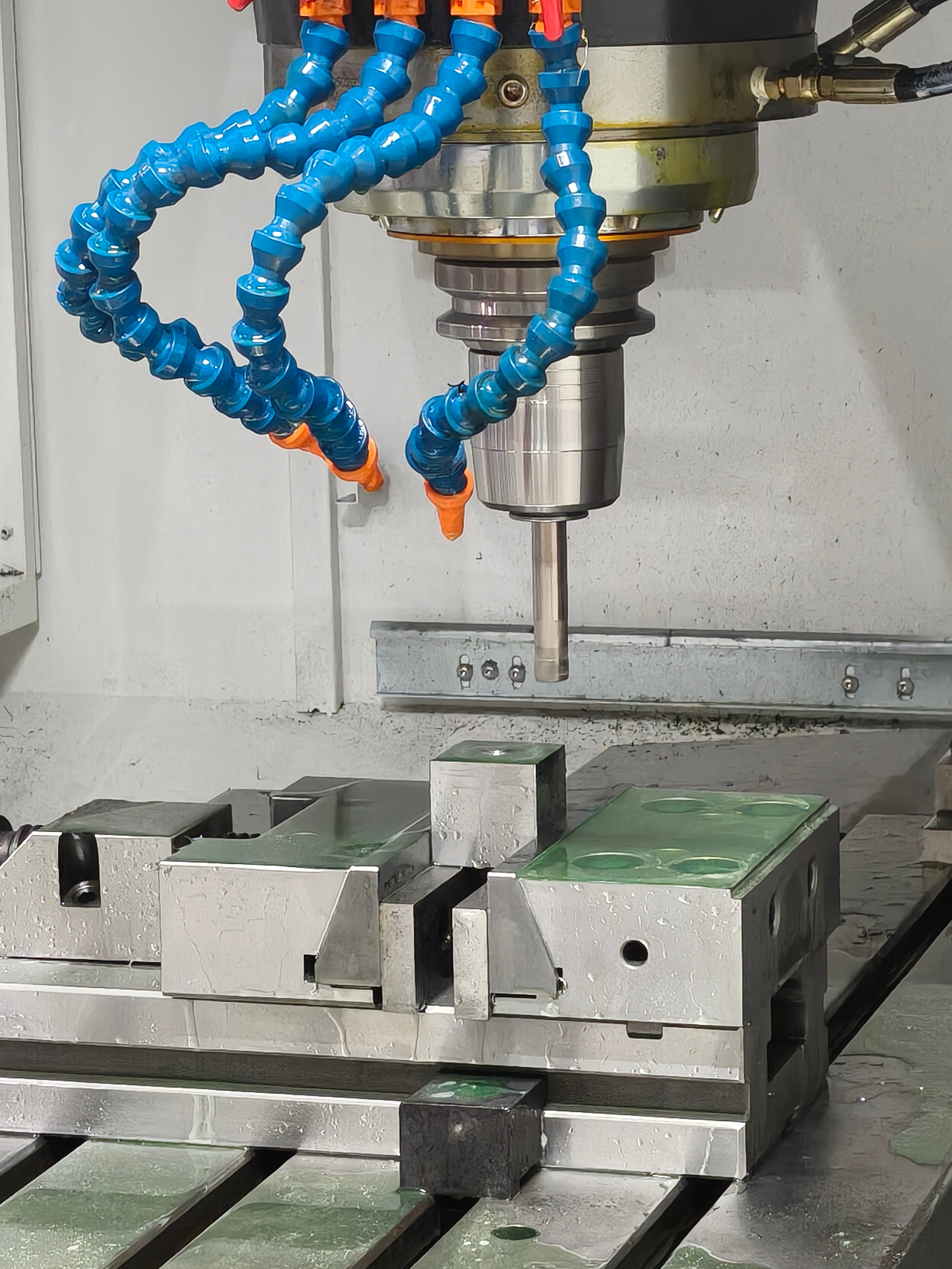
Suppose CAM is set for a 0.003 mm scallop and measured runout is 0.005 mm. Runout is already about 67% larger than the programmed cusp. Fixing the runout should come before changing the scallop to 0.002 mm.
Research on milling cutter runout shows that differences in the radial position of cutting teeth change chip load and can affect the finished surface.[4]
Before a critical finishing pass:
- clean the spindle taper
- clean the holder, collet and tool shank
- measure runout close to the cutting end
- replace damaged collets
- keep tool projection short
- use a cutter with a known edge condition
For fine mold work, record the runout value with the job data. A measured number is far more useful than simply noting that the holder looked clean.
Keep Tool Projection Short
Tool projection changes stiffness quickly. In a simple cantilever model, with the same tool section and side load, deflection changes roughly with the cube of unsupported length.
- 30 mm to 45 mm projection: theoretical deflection trend rises about 3.4 times
- 30 mm to 60 mm projection: theoretical deflection trend rises about 8 times
Those ratios are not exact predictions for a real milling cutter because cutting load changes with the setup. They do show the size of the effect. Adding another 20–30 mm of unnecessary overhang can make a finishing cut much less stable.
If 50 mm of projection reaches the surface with safe clearance, there is little reason to hang the tool out 100 mm just to avoid another tool setup.
For a deep cavity, split the finishing work when possible:
- short tool for open upper surfaces
- medium-reach tool for deeper walls
- long-reach cutter only where shorter tooling cannot reach
Going deeper into a cavity does not automatically mean tool projection has increased. If the same holder and cutter stay in the spindle, the physical overhang is unchanged. Check surface angle, remaining stock and cutter engagement before blaming reach alone.
Leave Even Stock Before Finishing
The final ball nose should cut a small, reasonably even layer of material.
For example, most of the mold may have 0.05–0.10 mm left for finishing while one corner still carries 0.25–0.30 mm. That corner has roughly 3 to 5 times as much stock as the lighter areas.
The cutter sees a much heavier load when it reaches that corner. If a band or patch appears there, tool deflection may be the cause rather than stepover.
Use this mold and die machining sequence:
- rough the cavity
- rest-rough areas the first tool missed
- semi-finish the surface
- check the CAM stock model
- remove isolated heavy stock
- run the final ball nose path
If the finishing tool reaches an area with 0.30 mm of stock when the planned allowance is 0.08 mm, add another semi-finishing or rest pass there. Making the final stepover smaller will not remove the uneven-load problem.
Separate Shallow and Steep Surfaces
| Surface | Starting Strategy |
|---|---|
| Flat or shallow surface | Parallel, spiral or scallop-controlled finishing |
| Steep wall | Constant-Z finishing |
| Small fillet | Rest finishing |
| Transition area | Cleanup pass if visible marks remain |
A 30–45° slope boundary can be a starting point when you split shallow and steep machining, but it is not a fixed standard. If one mold has a 10° floor, a 35° curved face and a 75° wall, inspect the three areas separately. One spacing method will not always leave the same pattern on all of them.
Check how your CAM software defines “scallop” as well. Different systems can handle spacing around boundaries, fillets and rapid curvature changes in different ways.
Check CAM Tolerance
Keep CAM tolerance smaller than the surface error you are trying to control.
If target scallop is 0.005 mm and CAM tolerance is 0.010 mm, the programmed path is allowed to deviate by twice the target cusp height. Reducing stepover does not correct that mismatch.
- target scallop: 0.003 mm
- CAM tolerance: 0.010 mm
- allowed path deviation: about 3.3 times the target scallop
Before running a very fine stepover, check:
- machining tolerance
- smoothing or arc-fitting tolerance
- postprocessor output
- controller look-ahead
- number of very short toolpath moves
Do not push tolerance to an extremely small value just because CAM accepts it. A program filled with very short moves can force some controls to slow down repeatedly on curved sections.
Avoid the Center of the Ball on Flat Surfaces
Cutting speed is zero at the exact center of a ball nose tip. Move away from the center and the effective cutting diameter increases, so surface speed rises.
When a ball nose runs vertically over a truly flat floor, the center of the tool can rub instead of cutting cleanly. You may see:
- dull or smeared marks
- more heat
- poor finish
- shorter edge life
On 5-axis or indexed 3+2 machining, tilting the tool moves the contact point away from the center of the ball. Research on 5-axis ball-end milling has shown that lead and tilt angles affect tool contact, cutting forces and surface behavior.[5]
A 5-axis machining center gives you that option when the part geometry, holder clearance and CAM toolpath support a tilted cutter.
Changing a 3-axis path from X direction to 45° or Y direction does not move the contact point away from the ball center on a horizontal floor. The feed marks may change direction, but the tool axis is still vertical.
Match Feed to Stepover
Stepover controls marks across neighboring passes. Feed per tooth affects the marks that run along each pass.
Suppose you have a 0.30 mm stepover and the visible marks follow the cutting direction. Reducing stepover to 0.20 mm increases path intervals by about 50% over the same width. If the real cause is a worn flute or poor feed, you have added half again as many passes without fixing it.
Check:
- feed per tooth
- spindle speed
- flute count
- runout
- edge wear
- chatter
If the defect follows the cutter's direction of travel, work through these items before reducing stepover again.
Consider Steel Hardness
Steel hardness does not change the scallop formula, but it does change how the cutter behaves.
The P20 / 1.2311 mold steel listed by AsiaTools is supplied pre-hardened at about 28–36 HRC. A finishing setup that works well in that range should not simply be copied to a much harder mold insert.
Research on finish ball-end milling of hardened steel found that surface inclination and cutting conditions affect cutting forces and machining efficiency.[6]
When steel hardness increases, check these areas closely:
- tool projection
- tool-holder rigidity
- finishing-stock consistency
- carbide grade and coating
- edge wear during long finishing cycles
If the first 20% of a long toolpath looks clean but the last 20% has much stronger feed marks, inspect cutter wear before tightening stepover across the entire program.
Calculate How Stepover Changes Cycle Time
For a simple raster path:
Path intervals ≈ Surface width ÷ Stepover
The actual number of cutter passes is usually about one more than the number of intervals. CAM may also extend paths beyond the edge, so machine time will not match this calculation exactly.
For a 120 mm-wide surface:
| Stepover | Approx. Path Intervals | Change vs 0.40 mm |
|---|---|---|
| 0.60 mm | 200 | 33% fewer |
| 0.40 mm | 300 | Baseline |
| 0.30 mm | 400 | 33% more |
| 0.20 mm | 600 | 100% more |
Reducing stepover from 0.40 mm to 0.20 mm takes the path count from roughly 300 intervals to 600.
If every path is about 180 mm long:
- 0.40 mm stepover: about 54 m of ideal cutting travel
- 0.30 mm stepover: about 72 m
- 0.20 mm stepover: about 108 m
At an average cutting feed of 3,000 mm/min, those distances equal about 18, 24 and 36 minutes of cutting motion. Actual machine time will be longer once lead-ins, linking moves, acceleration, deceleration and repositioning are added.
Include Polishing Time in the Decision
The fastest CNC program is not always the fastest way to finish the mold. A wider stepover saves machine time but may hand more work to the polishing bench.
| Stepover | CNC Finish Time | Polishing Time | Total Time |
|---|---|---|---|
| 0.40 mm | 40 min | 90 min | 130 min |
| 0.35 mm | 46 min | 55 min | 101 min |
| 0.30 mm | 54 min | 45 min | 99 min |
| 0.20 mm | 80 min | 40 min | 120 min |
These numbers are examples rather than standard production times.
In this example, changing stepover from 0.30 mm to 0.20 mm increases CNC finishing time from 54 to 80 minutes, about 48%. Polishing only drops from 45 to 40 minutes, about 11%. Total finishing time therefore increases from 99 to 120 minutes.
For repeat molds, record CNC time, polishing time and finishing-tool use for each job. After a few comparable jobs, your own shop data will give a better starting point than a generic cutter-diameter percentage.
Run a Small Test Before a Long Finish Cycle
If the calculation gives 0.346 mm stepover for a 6 mm ball nose, test values close to it instead of guessing across a wide range:
- 0.30 mm
- 0.35 mm
- 0.40 mm
Compared with 0.35 mm:
- 0.30 mm creates about 17% more path intervals
- 0.40 mm creates about 12.5% fewer path intervals
These three settings are close enough to compare surface finish fairly, while the difference in path count is still large enough to show up in cycle time.
Keep the rest of the setup unchanged:
- cutter and edge condition
- holder
- tool projection
- rpm
- feed
- remaining stock
- toolpath direction
- CAM tolerance
| Test Item | What to Record |
|---|---|
| Tool | Diameter, condition and projection |
| Runout | Measured value at the cutter |
| Cutting data | RPM, feed and flute count |
| CAM | Stepover, tolerance and path type |
| Material | Steel grade, hardness and finishing stock |
| Result | Surface marks, roughness, CNC time and polishing time |
If 0.40 mm already meets the finish requirement, keep it. If you can still see ridges between passes, compare 0.35 mm and 0.30 mm. Change one main variable per test so you can tell whether stepover actually caused the difference.
When a Ball Nose Cutter Becomes Too Slow
For a 300 mm-wide mold surface at 0.25 mm stepover:
300 ÷ 0.25 = 1,200 path intervals
If each path averages 400 mm:
1,200 × 400 mm = 480,000 mm = 480 m
At an average cutting feed of 3,000 mm/min, 480 m equals about 160 minutes of cutting travel. That is before linking moves, acceleration and repositioning are included.
On a large smooth surface, a barrel or lens-type cutter may be worth testing if the machine and CAM system support multi-axis finishing. Its larger effective cutting radius can allow much wider path spacing.
Check this option when:
- large smooth surfaces make up most of the mold
- ball nose finishing already takes several hours
- multi-axis motion is available
- CAM supports the cutter geometry
- tool and holder clearance can be verified
Keep the ball nose for deep cavities, small fillets and tight details where its geometry still gives better access.
Quick Stepover Check
| Situation | What to Do |
|---|---|
| Normal polished mold | Start around 0.010–0.020 mm scallop |
| Light polishing only | Test around 0.005–0.010 mm |
| Large open surface | Use the largest ball nose that safely fits |
| Small remaining fillet | Use a smaller cutter for rest finishing |
| Regular ridges between paths | Check stepover first |
| Marks along cutting direction | Check feed, edge wear and runout |
| Runout larger than target cusp | Fix runout before reducing stepover |
| Local stock several times heavier | Add a semi-finish or rest pass |
| Steep wall | Test constant-Z finishing |
| Flat floor finishes badly | Check ball-tip contact |
| Long tool vibrates | Reduce projection where possible |
| CAM tolerance exceeds target cusp | Correct tolerance before making stepover smaller |
| Cycle time is too long | Test the next wider stepover and inspect the surface |
FAQ
What is a good stepover for a 6 mm ball nose end mill?
A 6 mm ball nose needs about 0.49 mm stepover for a 0.010 mm theoretical scallop and about 0.35 mm for a 0.005 mm scallop on a locally flat surface. Those values are about 8.2% and 5.8% of cutter diameter. Start there, machine a test area, then check the actual finish before changing the program.
What percentage of cutter diameter should stepover be?
There is no single percentage that works for every mold. With a 6 mm cutter, 0.35 mm is about 5.8% of diameter while 0.49 mm is about 8.2%. Both settings can be correct because they produce different scallop heights. Choose the scallop first, then calculate the matching stepover.
Does smaller stepover always improve surface finish?
No. Reducing stepover from 0.40 mm to 0.20 mm roughly doubles the number of paths across the surface, but it mainly changes the cusp between neighboring passes. It will not fix chatter, excessive runout, a worn edge or poor feed settings. Look at the direction and shape of the surface marks before changing stepover.
Can scallop height be converted directly to Ra?
No reliable one-to-one conversion works for actual mold machining. Scallop height describes ideal toolpath geometry. Measured roughness also includes feed marks, vibration, cutter wear, runout and the measurement method. If Ra is specified on the drawing, machine and measure a test surface instead of treating the CAM scallop value as the final Ra.
Finally
Start with the finish the mold needs, then calculate the stepover. For a 6 mm ball nose, about 0.35 mm gives a 0.005 mm theoretical scallop and about 0.49 mm gives 0.010 mm. Before making the spacing tighter, check runout, CAM tolerance and remaining stock. Cutting stepover from 0.40 mm to 0.20 mm roughly doubles the number of paths across the same surface. A small test with 0.30, 0.35 and 0.40 mm often tells you more than another round of guessing. Keep the widest setting that meets the required finish and does not create extra polishing work.