

Checking a CNC chamfering machine for automatic measurement accuracy takes 4 separate runs. They cover geometry, axis positioning and repeatability, the finished test piece, and the probe itself. The standards are ISO 230-1:2012, ISO 230-2:2014, ISO 230-12:2022 and ISO 10360-2:2009. Two numbers decide the outcome, 0.08 mm of allowed uncertainty and 0.195 mm of uncontrolled thermal drift.
One rule holds for pass or fail. Measurement uncertainty stays inside one fifth of the drawing tolerance. A C4 chamfer drawn at ±0.2 mm gives a 0.4 mm band, so the allowance is 0.08 mm. The 5-axis stack takes 28% of that.
Heat is the line that breaks first. Steel grows 11.5 µm per m per °C. Warm a 1,400 mm plate by 5 °C and it grows 0.08 mm. A 2,000 mm machine axis grows 0.115 mm over the same 5 °C. Worst case the two add to 0.195 mm, or 2.4 times the 0.08 mm allowance.
One scrapped chamfer costs about 200 yuan to rework. Two wrong calls a shift cost 400 yuan, and 250 shifts a year reach 100,000 yuan. A gauge block and calibration set costs about 20,000 yuan, paid back in 50 shifts.
An in-machine probe reads the machine's own coordinate system. Axis error, thermal drift and stylus bending all land in that number. A passing probe reading is not a passing part. Acceptance goes back to an offline gauge on the finished piece, judged on the range of 25 touches.
Four error stages, five standards
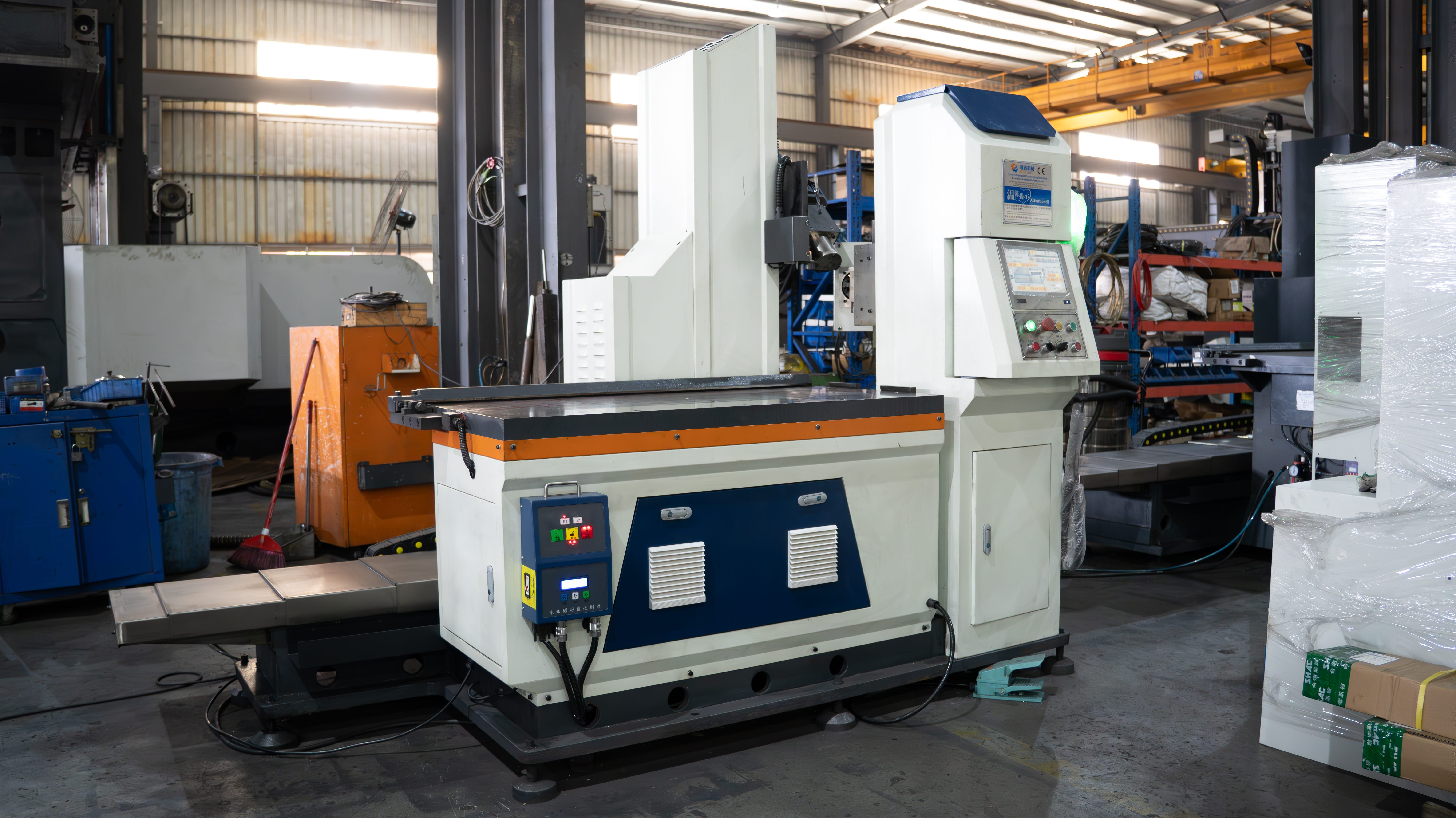
Automatic measurement on a chamfering machine means the in-machine probe touches the workpiece edge after a tool change, then writes the measured chamfer back into the CNC compensation table. All three DJX3 models, DJX3-1000-600S, DJX3-1200-700S and DJX3-1400-800S, carry 5 control axes and a φ90 mm cutter, with compensation on 3 linear axes.
Four stages need five standards. The tightest judgement sits at 0.001 mm on probe repeatability, the loosest at 0.195 mm on thermal growth. Between them the spread is 195 to 1.
| Stage | Error source | Governing standard | What it measures |
|---|---|---|---|
| Geometry | Column squareness, spindle axis against table face | ISO 230-1:2012 | No-load or quasi-static geometry |
| Axis | Positioning accuracy, repeatability, reversal value | ISO 230-2:2014 | Repeated runs in both directions |
| Test piece | Face length and face angle consistency | ISO 230-12:2022 | The part that comes off the machine |
| Probe | Stylus bending, sphere form, trigger repeatability | ISO 10360-2:2009 | The measuring system itself |
| Heat | Ambient change, spindle growth, linear axis drift | ISO 230-3:2020 | Drift after warm-up |
Geometry sets the static floor
A chamfering machine has few geometric items to check. Crossbeam parallel to the table, spindle axis square to the table face, and the 3 linear axes square to each other. The table measures 800×1,550 mm and the magnetic chuck 800×1,400 mm, so the 1,400 mm range is the one that matters.
A DJX3-1400-800S weighs 3,400 kg and measures 3,400×1,700×2,060 mm. Rated load is 2,000 kg, so the machine is 1.7 times its own payload. Smaller models DJX3-1000-600S and DJX3-1200-700S weigh 2,600 kg and 3,000 kg.
Squareness error of 0.02 mm over the 1,400 mm range travels straight to the chamfer face and takes 25% of the 0.08 mm allowance. Read 3 points or more across the range. Any 2 points differing by more than 0.02 mm fail the check.
ISO 230-1:2012 is edition 3, published March 2012, 160 pages, confirmed again in 2023. A 2,911 kg plate gets the same geometry tests in the large mould plate grinding guide. The standard covers geometric and machining tests under no-load or quasi-static conditions and leaves out vibration and stick-slip.[1]
Axis accuracy needs both directions
ISO 230-2:2014 is edition 4, published May 2014, 43 pages, confirmed in 2025, with a 2016 amendment. Run each target position 5 times in both directions. That gives unidirectional positioning accuracy, unidirectional repeatability and reversal value. Testing one direction only loses the screw backlash figure.[2]
The 5 servo axes on the DJX3 series are 1.0/1.0/1.0/1.0/1.5 kW, or 5.5 kW total, and the largest axis is 1.5 times the other 4. At 0.01 mm error per axis the root-sum-square across 5 axes is 0.0224 mm. The figure takes 28% of the 0.08 mm allowance and leaves 72% for heat.
The finished piece decides
ISO 230-12:2022 is edition 1, published June 2022, 46 pages. Clause 5 covers one surface, clause 6 covers the relationship between several machined features, and clause 7 adds short-term capability and thermal influence.[3]
Clamp a 1,400 mm P20 plate on the magnetic chuck, pre-hardened to 28–32 HRC, and chamfer 4 edges at C4. Chuck area is 1.12 m², so the 2,000 kg rated load works out to 1,786 kg/m².
The envelope and the load do not pair. A block at the top of the range, 300 mm thick by 800 mm wide by 1,400 mm long, weighs 2,637.6 kg at 7,850 kg/m³. The block is 32% over the rated load, so a full-footprint plate has to stay under 227 mm thick.
Pick a stock grade for the test piece, from 1045, 1.2311, 1.2344, 1.2738, 1.2083 or 12CrMo. Pre-machined blocks come off a TH-700NC duplex milling machine, and the pre-machined tolerance is ±0.01 mm.
A 45° C4 chamfer has a theoretical face length of 4×√2, or 5.657 mm. Tilt the head by 1° and the face becomes 4÷cos44°, or 5.561 mm. The 0.096 mm gap is 24% of the 0.4 mm band and also over the 0.08 mm allowance.
At its rated 2,825 rpm and a φ90 mm cutter, cutting speed is π×90×2,825÷1,000, or 799 m/min. That lands in the high-speed aluminium range.
P20 pre-hardened to 28–32 HRC runs 120–200 m/min with coated carbide, or 425–707 rpm. With a fixed spindle, hitting 150 m/min at 2,825 rpm takes a cutter of 150,000÷(π×2,825), or φ16.9 mm.
At 0.1 mm per tooth and 5 teeth the feed is 0.1×5×2,825, or 1,412 mm/min. One 1,400 mm C4 edge takes 59 s and removes 0.5×4×4×1,400, or 11,200 mm³ of steel. The volume is 11.2 cm³, weighing 88 g.
Three linked heads cut 3 edges per cycle, and 3 cycles finish the usual edges on a mould block. Add 10 min for loading and the part spends about 13 min on the machine. An 8 h shift of 480 min turns out 36 pieces, and 250 shifts a year reach 9,000 pieces.
Specific cutting energy of 2,000–2,500 N/mm² puts the same 11.2 cm³ at 0.38–0.47 kW in 59 s, or 51% to 63% of the 0.75 kW spindle. Keep it as an order of magnitude only. It leaves out edge radius, size effect and coolant.
Heat is the missed stage
ISO 230-3:2020 is edition 3, published November 2020, 50 pages in English. Its 4 tests cover environmental temperature variation, spindle rotation, linear axis motion and rotary motion of components. The linear axis test applies to NC machines and caps measured length at 2,000 mm.[4]
The expansion coefficient is 11.5 µm per m per °C. A 1,400 mm plate warmed by 5 °C grows 1.4×11.5×5, or 80.5 µm. That works out to 0.08 mm.
A 2,000 mm machine axis growing over the same 5 °C moves 2×11.5×5, or 115 µm, so 0.115 mm. With the two running in opposite directions the worst case adds to 0.08 + 0.115, or 0.195 mm.
That 0.195 mm is 2.4 times the 0.08 mm allowance and eats 98% of the ±0.2 mm single-side limit. In an uncontrolled shop the first 4 stages can all pass and the automatic reading still uses up the whole band.
Soak the workpiece and the machine together at 20±1 °C for 4 h. Hold the temperature spread under 1 °C and the same 1,400 mm length moves 1.4×11.5×1, or 16 µm. The figure is 0.016 mm.
At 0.016 mm the thermal stage takes 20% of the 0.08 mm allowance and finally fits. The gap between 16 µm and 195 µm is 12 to 1.
Rerun one geometric item after 2 h of continuous cutting. Drift above 0.016 mm means the thermal compensation table was never calibrated, or the coolant temperature is out of step with the shop.
The probe needs its own calibration
ISO 10360-2:2009 covers acceptance and reverification of coordinate measuring machines. Edition 3 came out in December 2009, 29 pages, confirmed in 2026, and it governs contacting probes in discrete-point mode for length measurement error and repeatability.[5]
An in-machine probe is not a CMM, but the error structure is the same. Stylus length, stylus bending, reference sphere form and trigger direction each contribute about 0.5 µm. The root-sum-square is 0.5×√4, or 1 µm, or 0.001 mm. That takes 1.3% of the 0.08 mm allowance.
Triple that 1.3% and it still lands at 3.9%, under 4%. The headroom buys a longer stylus or more trigger force margin.
NIST IR 5170 came out in April 1993 from Phillips, Borchardt and Caskey. Its subject is task-specific uncertainty, and a calibration certificate number is not the number for your task.[6]
The 25-touch range on a reference sphere covers 1 point. A 1,400 mm edge has 4 corners, so record 4 ranges and compare each against the 10 µm limit.
Eight things to do on site
- Log the ambient temperature against the machine manual range, with the workpiece and the machine soaked together for at least 4 h.
- Check crossbeam parallel and spindle squareness to ISO 230-1:2012, taking 3 points or more over the 1,400 mm range.
- Run both-direction positioning tests to ISO 230-2:2014 on the 3 linear axes, 5 repeats at every target position.
- Calibrate the in-machine probe on a 5 mm gauge block with 25 touches and record the range.
- Chamfer 4 edges at C4 on a 1,400 mm P20 plate and measure face length against the 5.657 mm theoretical value.
- Re-measure pieces 1, 20 and 40 from the same batch to see the drift.
- Idle the machine for 2 h at 2,825 rpm and repeat the geometry data from item 2.
- Write every reading, standard number and edition into an acceptance record that ships with the machine.
Gauges follow what you judge
Face length and face angle need separate measurements. A 0.01 mm caliper cannot read a 0.083° angle error.
| Check | Gauge | Resolution | Where it fits | Limitation |
|---|---|---|---|---|
| Face length | Image measuring machine | 0.001 mm | First piece and samples | Needs a 2D projection stage |
| Face length | Profile projector | 0.001 mm | First piece | Outline only, no depth |
| Face angle | Vernier bevel protractor | 5 min of arc, or 0.083° | First piece | Angle only, no size |
| Face angle | Sine bar with dial indicator | 0.01 mm | First piece | Slow to set, flat parts only |
| Edge leg | Digital caliper | 0.01 mm | Every piece | Rides the edge radius and reads high |
| Related dimensions | CMM | As stated by the builder | Reverification and disputes | Long turnaround |
That 0.083° step equals 0.008 mm of face length, one order finer than the 0.08 mm allowance. The 0.08 mm figure is the drawing tolerance, one of the seven inputs the mould steel chamfering checklist starts from.
- A caliper jaw riding an R0.2 mm edge radius reads about 0.06 mm high on one side.
- Light angle in an image measuring machine shifts the shadow edge by 1 or 2 pixels, so 0.001 mm of resolution is not 0.001 mm of accuracy.
- Face angle is checked on the first piece only; the head has no rotary axis, but spindle growth tilts it forward and back, so recheck after 40 pieces.
Pass and fail limits
| Item | Limit | Standard |
|---|---|---|
| Geometry | Parallel and square within 0.02 mm over 1,400 mm | ISO 230-1:2012 |
| Axis positioning | Both-direction stack within 0.0224 mm | ISO 230-2:2014 |
| Probe repeatability | Range of 25 touches within 10 µm | ISO 10360-2:2009 |
| Finished chamfer | Face length 5.657 mm, allowance 0.08 mm | ISO 230-12:2022 |
| Thermal drift | Geometry shift after 2 h within 0.016 mm | ISO 230-3:2020 |
Budget split
| Stage | Share | Of the 0.08 mm allowance | With temperature controlled |
|---|---|---|---|
| Geometry | 0.02 mm | 25% | 0.02 mm, or 25% |
| Axis | 0.0224 mm | 28% | 0.0224 mm, or 28% |
| Probe | 0.001 mm | 1.3% | 0.001 mm, or 1.3% |
| Heat | 0.195 mm | 244% | 0.016 mm, or 20% |
| Root-sum-square | 0.197 mm | 247% | 0.034 mm, or 43% |
Four items for the acceptance file
- Ambient temperature log, with soak time and both the workpiece and machine probe readings.
- Raw both-direction positioning numbers for the 3 linear axes, including every repeat at each target position.
- Finished chamfer record, naming the gauge, its resolution and the measuring position.
- Geometry recheck after continuous running, with the run time and spindle speed stated.
The cost account
Scrap or rework on one chamfer runs about 200 yuan. At 13 min a piece and 36 pieces a shift, 2 wrong calls cost 5.6% of output, or 400 yuan. Across 250 shifts that reaches 100,000 yuan a year, against 500 wrong calls out of 9,000 pieces.
A gauge block, a reference set and an image-measuring calibration certificate start around 20,000 yuan, treated as an order-of-magnitude figure and excluding the measuring machine itself. Divide 20,000 by 400 and the payback is 50 shifts, or about 2 months at 21 shifts a month.
Questions buyers ask
Small chamfers and the same limit
Only when C4 capacity is needed. Most mould blocks run C1, and a C1 drawing tightens the tolerance to ±0.05 mm, so the allowance drops to 0.02 mm. A compound chamfering machine AT-D900DR holds C0 to C5 in steel for those same C1 edges.
Can the in-machine probe replace offline checks
An in-machine probe does not replace offline checks on acceptance runs. The in-machine reading carries axis error and thermal drift, and ISO 10360-2:2009 treats it as process monitoring between periodic reverifications.
Does hardened steel change the limits
Hardened steel needs different limits. Going from 32 HRC to 50 HRC raises specific cutting energy by about 1.4 to 1.6 times and adds spindle and fixture deflection. Switch the test piece to the 50 HRC grade and reset the limits from the same cutting test.
Send the two numbers
The whole check turns on the heaviest workpiece and the longest edge you normally chamfer, because 2,000 kg and 1,400 mm set the thermal budget. Add the drawing tolerance on the chamfer and the steel grade, and our engineers come back within 24 hours with a line-by-line quote naming the model, the workholding and the cutting method.
Request a Factory-Direct QuotePrepared by engineers, in English, against your own print. No obligation.
Sources
- ISO 230-1:2012 Test code for machine tools, Part 1, Edition 3, 160 pages
- ISO 230-2:2014 Test code for machine tools, Part 2, Edition 4, 43 pages
- ISO 230-12:2022 Test code for machine tools, Part 12, Edition 1, 46 pages
- ISO 230-3:2020 Test code for machine tools, Part 3, Edition 3, 50 pages
- ISO 10360-2:2009 GPS acceptance and reverification tests for CMM, Part 2, Edition 3, 29 pages
- NIST IR 5170 Measurement Uncertainty Considerations for Coordinate Measuring Machines