

Choose a horizontal face milling machine when most of the work is repeated machining on the four vertical sides of large blocks. Choose a gantry machining center for broad top surfaces, pockets, and hole patterns. A 2,000 × 1,200 mm block needs about 2,332 mm of workpiece-only clearance to rotate around its center, so make sure the loaded part fits before comparing spindle power.
What Is the Main Difference Between These Machines?
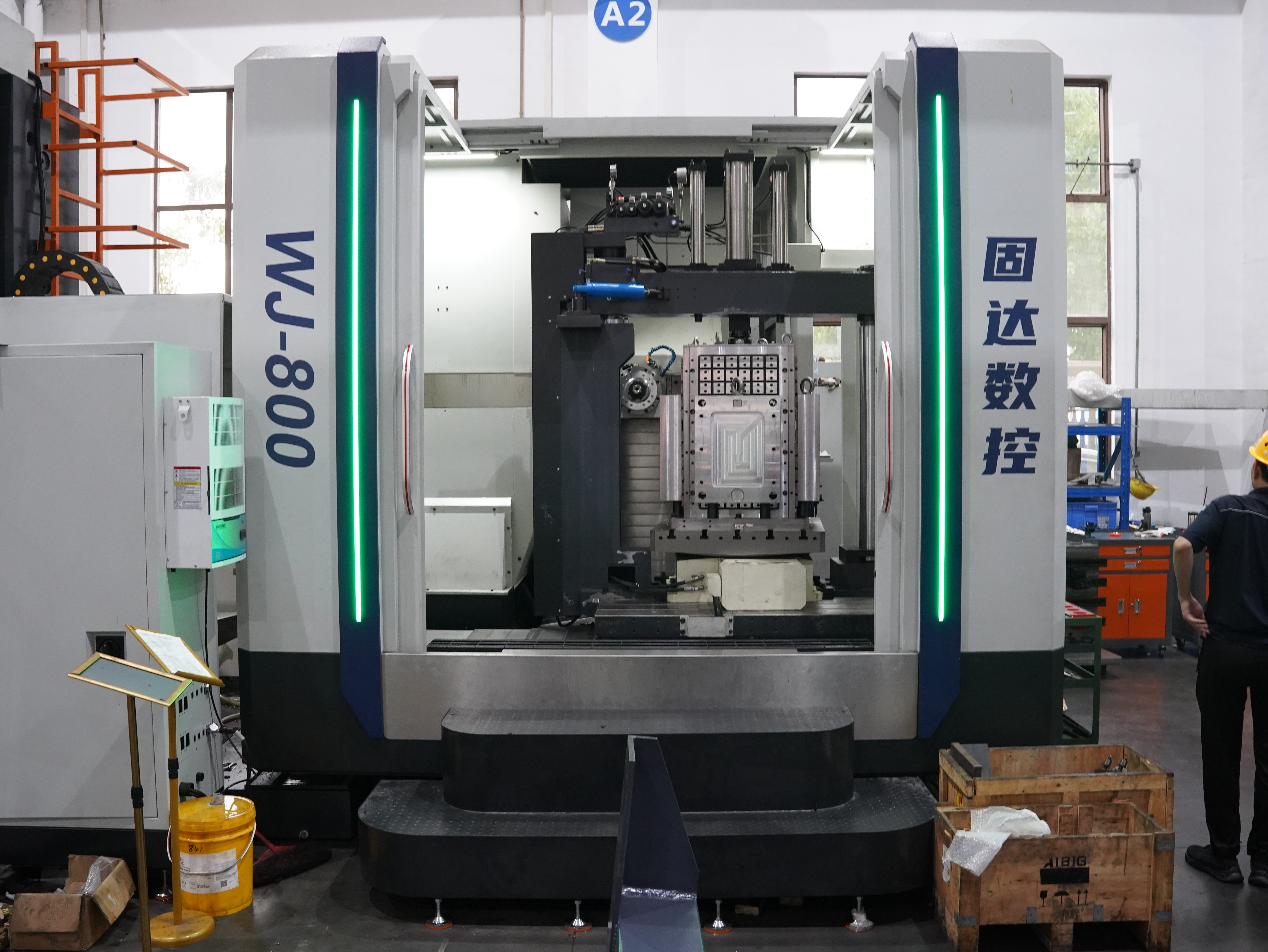
A horizontal face milling machine cuts from the side. Its horizontal spindle carries a face mill across a vertical surface. With an indexing table, the block can turn to another face without being lifted off the fixture.
The HM-3000 horizontal face milling machine, for example, uses a turntable to machine four end faces. That works well for block preparation, but part size, weight, and rotation clearance still have to fit the actual job.
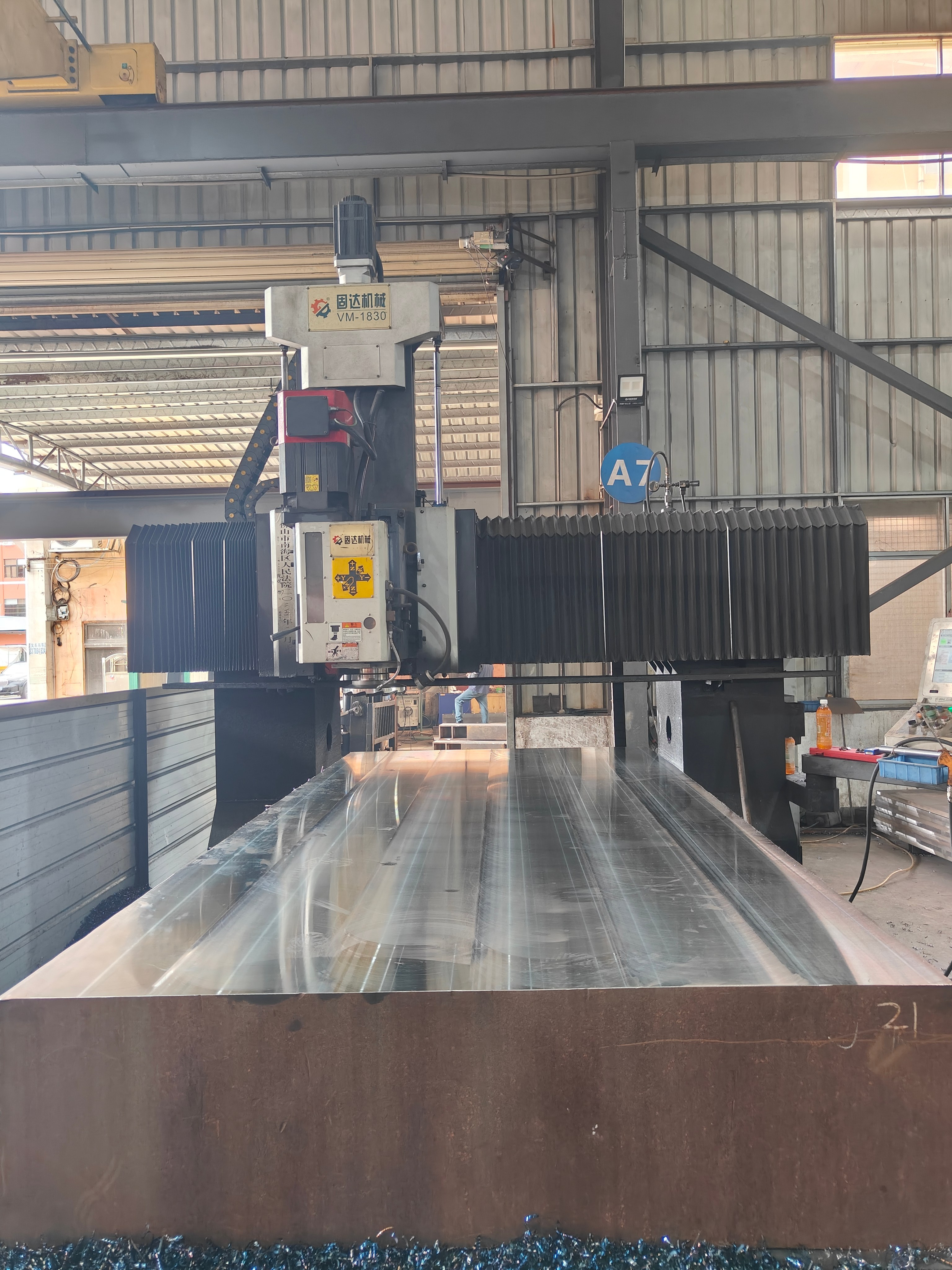
A gantry machining center normally approaches from above with a vertical spindle. Some designs move the table under the bridge; others move the gantry over a stationary workpiece. Angle heads can open up access to side faces as well.
A dedicated face mill is not the same thing as a general-purpose horizontal machining center. If you also need drilling, tapping, boring, pocketing, or automatic tool changes, check those operations separately. A machine that squares a block may still leave the holes and cavities for another machine.
Horizontal Face Milling Machine vs Gantry Machining Center at a Glance
| Production requirement | Machine to evaluate first | What to verify |
|---|---|---|
| Repeatedly square four vertical sides of steel blocks | Horizontal face milling machine with indexing table | Loaded rotation clearance, face coverage, squareness, and parallelism |
| Face the broad upper surface of a large plate | Gantry machining center | Travel, crossrail clearance, support positions, and cutter access |
| Machine pockets, top faces, and hole patterns | Gantry machining center | Spindle specification, tool magazine, pocket depth, and usable tool reach |
| Machine top and side features from one clamping | Gantry with suitable accessory heads | Head dimensions, attachment torque, clamp interference, and changeover time |
| Machine a long frame that is difficult to move | Moving-gantry machine with stationary workpiece | Support layout, working envelope, foundation, and loading access |
| Prepare blocks before detailed CNC machining elsewhere | Horizontal face milling machine | Preparation volume and the complete route through the remaining machines |
| Produce precision side bores in large housings | Evaluate a horizontal boring and milling center as well | Boring capability, spindle access, tooling, and datum control |
Start With the Surfaces You Need to Cut
A rectangular block has six outer faces. If an indexing face mill handles the four vertical sides, the top and bottom still need another operation unless the quoted machine has a way to reach them.
Take a mold plate with four side faces, two pockets on top, and 24 drilled holes. A dedicated face mill may handle the sides quickly. The pockets and holes are another story. A suitable gantry can often combine the top work, while side access still depends on the head arrangement.
For finished mold bases, count drilling, boring, tapping, and inspection as part of the route, not as work that somehow disappears after the faces are milled.
“Five-face machining” also does not mean every side feature is reachable. A recessed surface can still be blocked by the part, fixture, or machine column.
Calculate the Workpiece Weight Before Checking Table Capacity
Use raw-stock dimensions for the weight estimate. Finished size can be quite a bit lighter when the blank still has a lot of machining allowance on it.
For solid steel, a simple planning calculation is:
Weight in kg = length in m × width in m × thickness in m × 7,850
With a density assumption of 7,850 kg/m³, a 2,000 × 1,200 × 300 mm block weighs about 5,652 kg. Add a hypothetical 450 kg fixture and support assembly and the total becomes 6,102 kg.
| Example load item | Weight | Buyer’s check |
|---|---|---|
| Solid steel block, 2,000 × 1,200 × 300 mm | Approximately 5,652 kg | Confirm actual material density and raw-stock dimensions |
| Assumed fixture and support assembly | 450 kg | Include every component carried by the table |
| Combined example load | Approximately 6,102 kg | Exceeds a 6,000 kg rating before considering any other limits |
Being under the headline table-load number is not the end of the check. Support area, center of gravity, and indexing position can still matter, especially on a large block.
If you buy mold steel blanks, say whether the quote is for sawn stock or pre-machined stock. That changes the starting size, weight, and amount of material left to remove.
Check Rotation Space and Loaded Height
When a rectangular block turns around its center, its diagonal sets the workpiece-only swept diameter. For a 2,000 × 1,200 mm block:
Workpiece-only swept diameter = √(2,000² + 1,200²) ≈ 2,332 mm
Clamps can stick out beyond that number, and off-center loading makes the sweep larger. The safest way to check it is with a layout of the full loaded fixture through the complete indexing movement.
For a gantry, height stacks up too. A 300 mm block sitting on 150 mm of fixtures already gives you a 450 mm loaded stack before the tool and retract clearance are added.
| Clearance check | Horizontal face milling machine | Gantry machining center |
|---|---|---|
| Width and length | Cutting range and loaded indexing envelope | Travel limits and clear width between structural members |
| Height | Spindle centerline range and full face coverage | Loaded stack, installed tooling, and crossrail clearance |
| Cutter movement | Approach, exit, and clamp interference | Approach, cutting reach, retraction, and head changes |
| Loading | Crane access around the table and clamping structure | Crane access around the bridge, enclosure, and crossrail |
Z-axis travel is not the same as usable workpiece height. The real setup includes the fixture, holder, cutter, and tallest part all at once.
Will the largest block still fit after the fixture goes on?
Send ASIATOOLS the raw-stock dimensions, total loaded weight, and faces you need to machine. The setup can then be checked for table capacity, indexing space, and tool access.
Check My Workpiece CapacityDecide Whether the Workpiece Should Move
On a moving-table gantry, the table carries the workpiece through the cutting stroke. That means the full travel and loading area have to work with the installed part.
On a moving-gantry machine, the workpiece can stay still while the bridge travels over it.
With an indexing horizontal face mill, the static table-load number is not enough on its own. The part and fixture also have to be acceptable while the table rotates.
Compare Torque at the Actual Cutting Speed
For large cutters, low-speed torque matters more than a big maximum-rpm number.
Take a 250 mm cutter at an illustrative cutting speed of 180 m/min:
Spindle speed = (1,000 × 180) ÷ (π × 250) ≈ 229 rpm
At the same cutting speed, a 125 mm cutter runs at about 458 rpm. These are calculation examples, not recommended settings for an unspecified material.
Compare both machines with the same material, hardness, cutter diameter, width, depth, and feed. More importantly, compare continuous output at the rpm you will actually use, not one machine's peak rating against another machine's continuous rating.
If the gantry uses an angle head, check that head separately. Its torque, speed, and duty limits may be lower than the main spindle's.
Test the Cut at the Longest Reach
Tool reach changes the job. Record the overhang and ram extension at the feature that is hardest to reach.
If production needs a 300 mm tool assembly, testing with a 150 mm assembly makes the trial look easier than the real job. Use the production reach and comparable support conditions.
Then watch for chatter, surface marks, and dimensional movement. If the supplier has to reduce the cut to get an acceptable part, that slower setting should go into the cycle-time estimate.
Compare Finished-Part Accuracy and Measurement Conditions
Axis positioning and repeatability are separate measurements. ISO 230-2 defines methods for evaluating those characteristics on numerically controlled linear and rotary axes; it does not assign one universal finished-part tolerance to every machine.[1]
Turn the drawing into inspection points. If flatness is specified as 0.05 mm over a 2,000 mm face, measuring only a 300 mm section does not prove the full face meets the requirement.
| Drawing requirement | Evidence to request |
|---|---|
| Flatness | Measurements covering the full specified surface |
| Parallelism | Results referenced to the specified datum face |
| Squareness | Results after the proposed indexing or repositioning sequence |
| Hole position | Measurements across the required hole pattern and working span |
| Surface roughness | Results from the specified material and finishing process |
| Unclamped geometry | Inspection under the drawing’s required support and restraint conditions |
Temperature matters on large parts. NIST research shows that temperature and thermal-expansion uncertainty affect dimensional measurement away from the reference temperature.[2]
For scale, assume steel expands at 12 µm/m/°C. A 2 m length warming by 5°C changes by about 0.12 mm: 12 × 2 × 5 = 120 µm. That shows dimensional growth, not flatness error.
ISO 230-3 covers environmental temperature effects and thermal distortion linked to spindles, linear motion, and rotary components.[3]
If the drawing requires inspection after unclamping, put that condition into the trial as well.
Compare both machines on the material you actually use.
Provide the steel grade, hardness, stock allowance, and critical dimensions. Ask ASIATOOLS to quote the tooling, machining route, and trial conditions around that part.
Discuss My Machining RequirementsCount Handling Time in the Complete Cycle
Cutting time can look great while the total process is still slow. This example uses the same acceptance criteria for both routes:
| Activity | Process A | Process B |
|---|---|---|
| Loading and initial setup | 25 min | 25 min |
| Cutting | 40 min | 32 min |
| Indexing or repositioning | 6 min | 30 min |
| Inspection and unloading | 14 min | 14 min |
| Total cycle | 85 min | 101 min |
Process B cuts eight minutes faster, yet finishes the full cycle sixteen minutes later. Across 100 parts, that difference reaches about 26.7 hours.
If one setup removes a 20-minute reclamping step across 60 parts, that is 20 hours per month. Just count any new indexing, probing, or head-changing time too.
What Should You Send With Your Request for Quotation?
- Finished drawing and raw-stock dimensions.
- Material grade, hardness, and delivery condition.
- Maximum workpiece weight and estimated fixture weight.
- Machined faces, datums, tolerances, and surface-finish requirements.
- Stock allowance on each surface.
- Typical batch size and monthly or annual quantity.
- Available floor space, loading method, and crane access.
- Required trial-cut and inspection conditions.
Request a quote around your actual drawings.
Share your largest workpiece, normal batch size, and full operation list with ASIATOOLS. Ask for the proposed machine, required fixtures, and any operation that still needs another setup.
Send Drawings for a Technical QuoteFinally
For repeated side-face squaring, a horizontal face mill is usually the more direct route. For broad top surfaces and mixed features, a gantry gives you more flexibility. Compare the full cycle on your own part. Cutting 20 minutes of reclamping from 60 parts frees 20 hours a month, as long as the process still holds the required tolerances.