

FAT checks the machine at the supplier’s factory before shipment; SAT checks it at the buyer’s site after installation. At FAT, verify the ordered configuration, accuracy, tool changes, and test parts. At SAT, check the installation, repeat the agreed accuracy tests, and verify production cycle time and connected equipment. A FAT pass does not establish performance after transport and installation.
The figures below are examples, not industry-wide acceptance limits. Put the test methods, conditions, limits, and retest requirements in the purchase agreement.
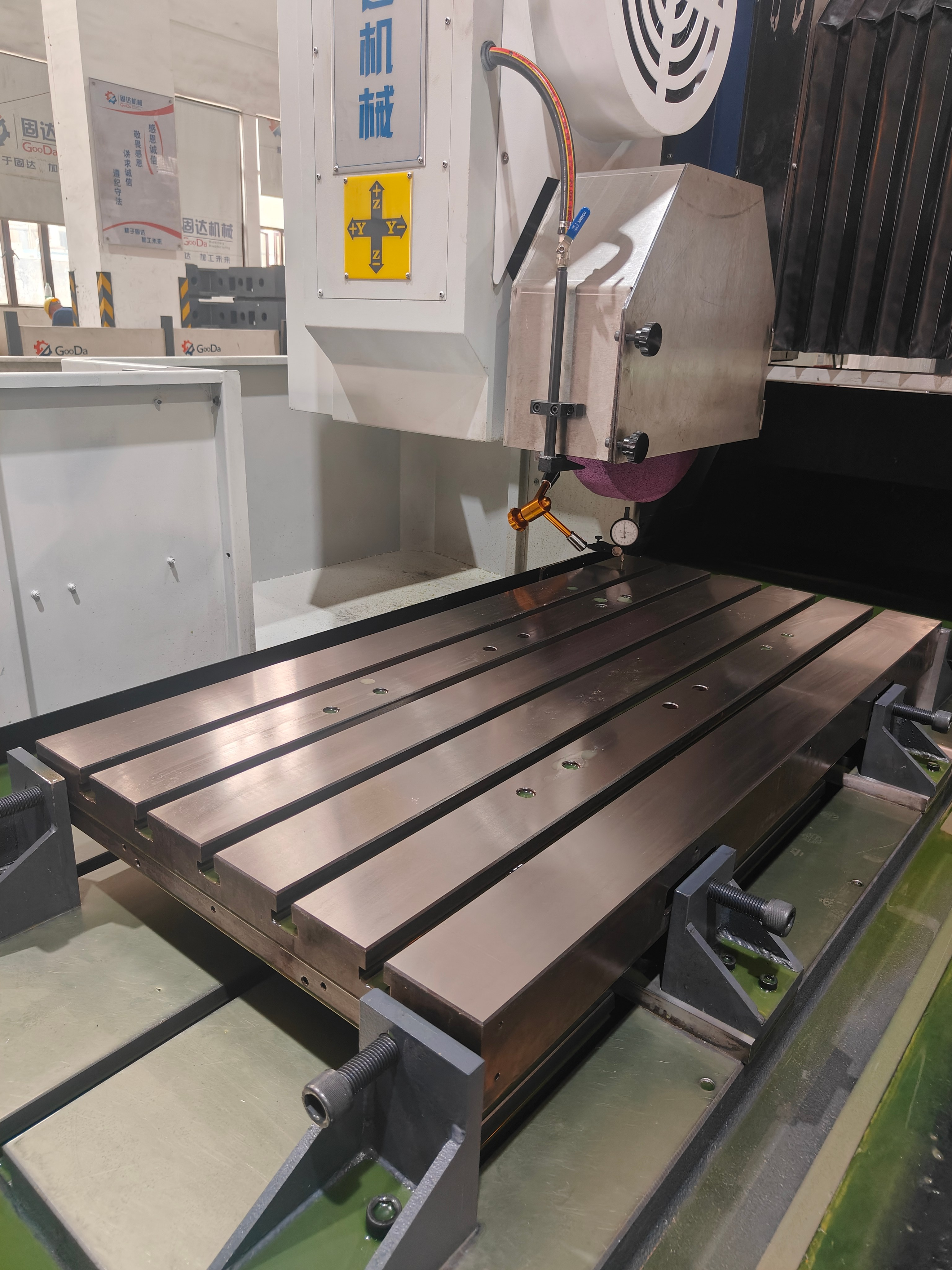
FAT and SAT Checks
| Item | FAT: Before Shipment | SAT: After Installation |
|---|---|---|
| Configuration | Match the machine, options, and software licenses to the order. | Check the serial number, delivered items, damage, and changes since FAT. |
| Accuracy | Measure the specified geometry and axis positioning performance. | Repeat the agreed tests after leveling and commissioning. |
| Cutting | Machine the agreed test piece and record individual measurements. | Verify results with the site’s agreed tooling, fixtures, and process. |
| Functions | Test the spindle, axis movement, tool changes, coolant, and chip removal. | Test loading equipment, interfaces, alarms, and recovery. |
| Safety | Test applicable guards, interlocks, and emergency stops. | Verify safety functions across the installed system. |
| Release | Record whether shipment is approved and list outstanding items. | Record the acceptance decision, remaining work, and handover documents. |
Configuration and Tool Changes
For a 24-position tool magazine, verify the positions and tool calls, then check tool length, diameter, and weight restrictions. Large tools may require adjacent positions to remain empty. On a dual-tool-magazine vertical machining center, include tool calls from both magazines.
If the machine completes 30 tool changes but requires an operator to clear two alarms, record “30 completed; two manual interventions.” Include the affected positions, alarm codes, and recovery steps. Do not report only a 100% completion rate.
For a cutting process that runs at 3,000 rpm, check available spindle power and torque at that speed, including continuous and short-duty ratings. Test purchased probes, tool setters, rotary tables, and software functions on the machine being shipped.
Accuracy and Measurement
Specify the axis, travel range, measurement directions, test points, and repeat count. A FAT test over 0–500 mm and a SAT test over 0–100 mm cannot establish a comparison across the full agreed travel. ISO 230-2 provides methods for measuring positioning accuracy and repeatability on individual linear and rotary axes.[1]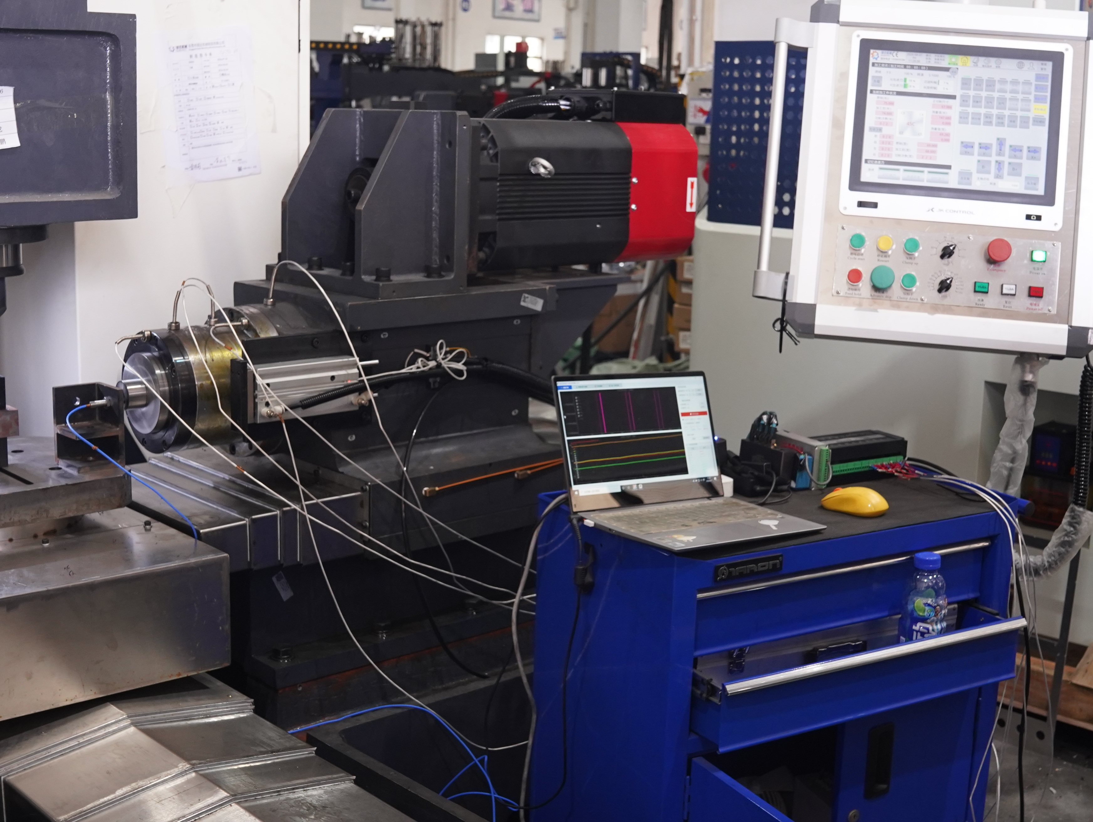
A bore specified as 50.000 ±0.010 mm has limits of 49.990–50.010 mm—a 20-micrometer tolerance band. Define the measurement sections and directions. Diameter readings at the entrance, middle, and exit do not replace separate roundness, cylindricity, or position checks.
A reading of 50.009 mm is 1 micrometer below the upper limit. If its expanded measurement uncertainty is ±2 micrometers, the corresponding interval crosses that limit. Apply the agreed conformity decision rule rather than accepting or rejecting the part from the displayed value alone.[2]
When comparing FAT and SAT, check temperature, warm-up, instruments, compensation settings, and leveling records. If the same metric rises from 0.006 mm to 0.009 mm, it has increased by 3 micrometers; that difference alone neither identifies transport damage nor determines acceptance.
Test Parts and Dimensional Drift
Fix the material grade and condition, blank size, fixture, tools, program version, and coolant setup in the test plan. A stainless-steel deep-hole application needs a corresponding drilling trial. Face milling aluminum does not test that drilling load or chip evacuation.
ISO 10791-7 specifies machining-center test pieces for assessing cutting accuracy under finishing conditions. Use the applicable tests alongside any production-part trial needed for your purchase.[3]
If a dimension moves steadily from 50.002 mm to 50.009 mm over 10 parts, it has shifted by 7 micrometers. All readings remain within 50.000 ±0.010 mm, but the trend warrants investigation. Record tool-offset changes, tool replacements, and stops against the affected part numbers.
If the contract requires Cp or Cpk, agree on sampling, sample size, calculation method, measurement-system suitability, and process stability. Ten trial parts alone do not demonstrate stable production capability; capability estimates also depend on the data’s distribution and sampling assumptions.[4]
Installation and Production Rate
Before installation, photograph shipping damage, leaks, and missing items. After installation, document foundation and leveling checks, electrical supply, air supply, and the specified environmental conditions.
If the installation requirement is at least 0.60 MPa at the machine inlet during operation, a receiver reading of 0.70 MPa is insufficient evidence. An inlet pressure of 0.55 MPa during a tool change would fail that requirement.
| Measurement | Result |
|---|---|
| Machining and in-machine auxiliary time | 6 minutes |
| Additional loading and unloading time | 2 minutes, with no overlap |
| Complete cycle | 8 minutes: theoretical output of 7.5 parts/hour |
| Observed output over 120 minutes | 14 completed; 13 accepted |
| Accepted-part rate for that period | 13 ÷ 2 = 6.5 parts/hour |
Agree on cycle start and end events, observation duration, and downtime exclusions. Count overlapping activities only once. Record rejected parts and stoppages; the observed rate applies to that test period, not automatically to every production shift.
Safety and Fault Recovery
Qualified personnel should test guard interlocks, emergency stops, clamp monitoring, and connected equipment using approved procedures. Record the required response and restart conditions. ISO 16090-1 covers applicable machining centers, milling machines, and transfer machines, including relevant workpiece handling and powered clamping equipment.[5]
For a hydraulic clamping system, verify the specified operating pressure and clamp-confirmation logic. In an automated cell, include missing material, an unconfirmed clamp, and an interrupted cycle in the recovery tests.
For example, simulate “clamp not confirmed” through the manufacturer-approved procedure. Check the machining inhibit, alarm, and clamp checks required before restart. Never create this fault by loosening a workpiece during cutting.
Checks by Machine Type
- CNC lathes: Check chuck reclamping repeatability, turret positioning, and tailstock or subspindle alignment.
- Five-axis machines: For a five-axis CNC machining center, include rotary-axis accuracy, kinematic calibration, and the agreed simultaneous machining path. Fixed-angle cutting does not verify simultaneous five-axis performance.
- Large machines: Cover the agreed travel range, foundation requirements, thermal conditions, and representative loads.
Reports and Acceptance
Each result should identify the machine serial number, specification revision, contract limit, test conditions, instrument and calibration details, raw data, and decision. Agree on independent checks for critical dimensions where needed; assess an in-machine probe’s capability before using it as the sole inspection evidence.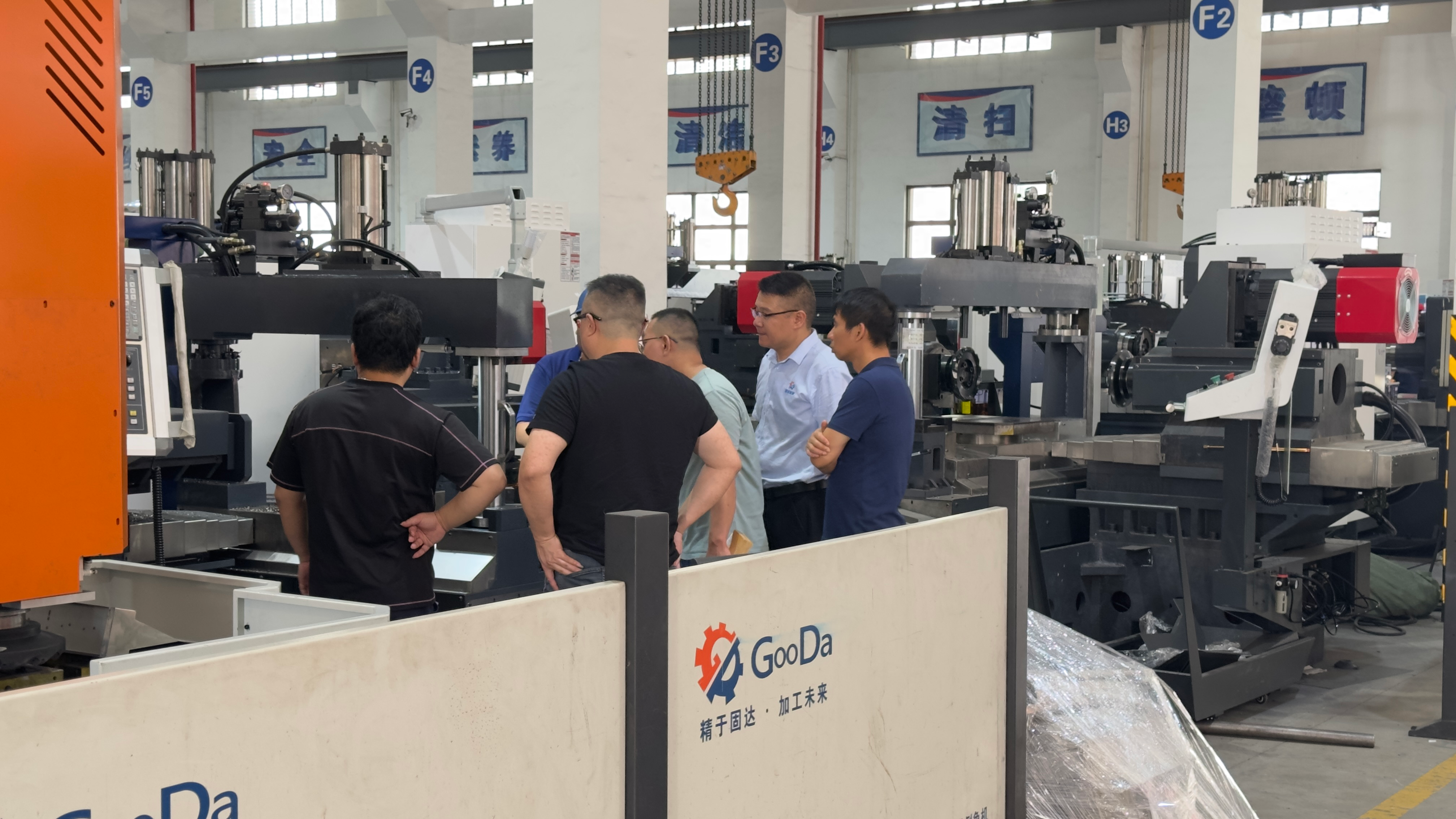
After changing X-axis error compensation, retest the agreed range and determine which part features need rechecking. Testing only the original failed point leaves the rest unverified. Close safety defects and critical performance failures only after corrective work and the required retests.
Collect operating and maintenance manuals, relevant drawings, parameter and compensation backups, programs, licenses, and calibration records. Training records should identify the operator or maintenance technician, the task performed, and the result.
Keep shipment approval separate from final acceptance. State the decision on the signed report and attach any outstanding-item list, with an owner, deadline, and closure evidence for each item. Apply the contract’s payment and warranty terms.