The dual-head milling machine uses a “single setup, simultaneous milling on both sides” process, completely eliminating the cumulative errors caused by repeated flipping and reclamping.
This method keeps the mold base’s flatness and squareness tolerances strictly within 0.01 mm.
It not only boosts milling efficiency by 50%, but also removes the need for tedious manual finishing afterward, cutting rework by 90% and ensuring consistently high mold-base quality.
Flatness
Traditional Machining
A medium-carbon steel plate, 1,200 mm long and 800 mm wide, has just arrived in the workshop. It weighs 2.8 tons, and its surface is still covered with the dark brown, rough oxide scale left from the steel mill.
The workshop’s 5-ton overhead crane lowers its heavy wire-rope hook and places the plate onto the worktable of an old gantry milling machine. The machine bed is a cast-iron platform with grooves spaced 150 mm apart. The machinist pulls out a long 36 mm wrench and, with six heavy mechanical clamps, tightens the M24 high-strength bolts down hard. With 800 N·m of torque, the wrench forces the steel plate firmly against the table.
Because the underside of the scaled plate is uneven, there is a gap of about 0.1 to 0.3 mm between it and the table. Under that extreme clamping force, the plate bends slightly and is forced to conform to the cast-iron surface beneath it.
A giant face mill with a diameter of 250 mm begins to spin. Twelve carbide inserts strike the steel plate at 450 rpm. The cutting depth is set to 3 mm, and the sharp sound of metal tearing immediately drowns out the workshop noise.
The flying chips instantly reach 400°C. Blue-hot fragments slam into the machine’s clear safety shield like buckshot. The hard black scale is stripped away layer by layer, gradually exposing the bright silver metal underneath.
The steel had previously been forged and quenched in a furnace at 1,100°C, leaving internal stresses locked inside. Once 3 mm is removed from one side, that balance is broken. In the center of the 2.8-ton plate, a silent upward bow of 0.08 mm appears.
· Removing the scale releases the steel’s internal compressive stress
· The metal loses restraint on one side and deforms slightly
· High-speed friction drives the surface temperature up by 300°C
· Thermal expansion makes the upward bow even more pronounced
Once the first side is finished, the machinist loosens the six M24 bolts. With a dull bang, the plate springs slightly. The crane moves in again, lifts it 2 meters into the air, and two workers struggle to flip it over.
Now Side A, with its slight curvature, faces downward on the table. The plate rocks slightly, like a table with uneven legs. The machinist crouches down and inserts several 0.05 mm brass shims into the fine gap to level it.
Once the shims are in place, the wrench comes down hard again. The huge clamping force pushes the warped section back down, forcing Side A tightly against the table once more. The cutter resets to its starting point and removes 3 mm from Side B in the same way.
After machining, a dial indicator glides across the freshly cut B surface. The needle barely moves, showing less than 0.01 mm of error. Satisfied, the machinist removes all the fixtures. But once the external force is gone, the 1.2-meter plate deforms immediately.
Within seconds of unclamping, the center rises again by 0.06 mm. A human hair is about 0.08 mm thick. When two mold plates are assembled, even a 0.06 mm gap is enough for molten plastic under 1,000 bar of pressure to flash out through the seam.
· The plate is moved to a granite inspection table in a temperature-controlled room
· Two plates are stacked together, and a 0.02 mm feeler gauge checks the gap
· Red lead paste is applied to the underside of a cast-iron straightedge to locate high spots
· The raised areas are marked with a dense grid using a black marker
A fitter walks over carrying a 2 kg carbide hand scraper. Leaning forward and using his body weight, he pushes it across the surface. The scraper is razor sharp, but each pass removes only 0.002 mm from the areas marked by the red paste.
On a raised area just 200 mm square, the fitter pushes the scraper more than 500 times. The workshop fills with the harsh scraping sound of steel against steel. Clean the surface, reapply red paste, check against the straightedge, scrape again—the cycle repeats over and over.
To remove a 0.04 mm high spot from a 1.2-meter plate, two experienced fitters must alternate for a full 14 hours. A single mold set uses eight thick steel plates like this, and each one has to be flattened by hand.
The delivery schedule is pushed back by 5 to 7 days. Labor costs in the plant are USD 50 per hour, and the hand-scraping alone eats away nearly all the profit from machining the plate. The S50C medium-carbon steel plate costs USD 1,500, while the manual scraping and leveling cost rises to USD 1,400.
Simultaneous Two-Sided Machining
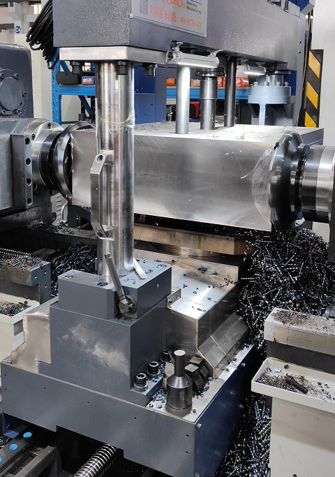
The crane uses two 5-ton nylon slings to move the 1,200 mm × 800 mm medium-carbon steel plate to the other end of the workshop. There stands a new dual-head milling machine occupying 30 square meters.
Instead, it uses four sets of heavy hydraulic clamping blocks. The operator presses the green start button, the hydraulic station hums to life, and the pressure gauge stabilizes at 150 bar. The four clamp sets extend from the top and bottom and grip only the 80 mm-wide narrow side edges of the plate with 6 tons of mechanical clamping force.
The 2.8-ton plate stands vertically like a wall on two hardened guide rails. Its two main machining surfaces, with a combined area of 0.96 m², hang completely free in the air. No heavy clamp is forcing the metal out of its natural physical state.
On either side stands a 5-ton spindle head. Two 37 kW Siemens motors power up and warm the spindles. Two 315 mm face mills move toward one another, each fitted with 16 carbide inserts coated with a titanium alloy.
Like two giant palms closing in, they slowly approach the steel plate covered in dark brown oxide scale. The cutting parameters are set to a feed rate of 800 mm per minute, with both left and right cutters removing 3 mm inward. All 32 inserts bite into the rough steel surface at virtually the same instant.
The sound of violent metal cutting erupts, and chips from both sides spray downward like twin fire streams into the chain-type chip conveyor below. The left spindle applies 5,000 N of force to the right, while the right spindle applies an exactly matched 5,000 N to the left.
The two destructive forces collide head-on inside the 2.8-ton steel plate, and their vectors cancel each other out completely. Suspended upright on the rails, the plate remains perfectly stable, without even 0.01 mm of bending deformation.
The instant the surface scale is removed, the internal stresses in the steel are released. The deformation force released by removing 3 mm from the left side is exactly countered by the force released by removing 3 mm from the right. On a microscopic level, the internal stresses are neutralized in perfect symmetry.
The heat generated by high-speed cutting is also dissipated evenly, carried away in chips from both sides at roughly 210°C.
| Comparison Dimension | Conventional Single-Side Machining | New Two-Sided Synchronous Method |
| Total cutter contact area | 0.48 m² on one side | 0.96 m² on both sides simultaneously |
| Peak cutting temperature rise | Localized 380°C on one side | Symmetrical 210°C on both sides |
| Elastic rebound after release | 0.08 mm one-way upward warp | Surface variation under 0.01 mm |
| Time spent flipping and reclamping | 45 minutes with crane and labor | 0 minutes, no flipping required |
The two cutters travel smoothly along the full 1,200 mm length and complete the pass. The control panel flashes a green “cutting complete” signal. Only 45 minutes have passed. The left and right spindle heads retract 2 meters, and the hot mist rising from the metal gradually dissipates.
The rough black-scaled steel plate is gone, replaced by bright silver metal with fine curved tool marks. The machinist releases the hydraulic switch, and the four clamps disengage instantly. Freed from the 6-ton clamping force, the 2.8-ton plate remains perfectly straight.
The crane lays it flat on the 2-meter granite inspection table in the temperature-controlled room. The machinist takes out a micrometer with 0.005 mm precision and slides it along the freshly machined surface. The ruby needle on the dial barely moves.
The overhead lights are turned off, and a strong flashlight is aimed flush against the granite surface. Not a trace of light can be seen between the steel plate and the inspection table. The machinist then takes the thinnest 0.02 mm feeler gauge and tries to force it into the gap. The tip bends, but it still will not go in.
No one in the workshop needs to coat the contact surface with thick red lead paste to search for high spots anymore. The 2 kg carbide hand scraper is finally put away at the bottom of a rusty toolbox.
Two giant mold plates processed by simultaneous two-sided cutting are stacked together, and the seam locks shut completely. A worker taps them lightly with a copper hammer weighing half a jin. Four precision steel locating pins, each 30 mm in diameter, slide smoothly through the pre-machined assembly holes.
What once required two experienced fitters sweating over 14 hours of scraping has become history on the shop floor. The foreman moves the assembly progress chart forward by a full five days with a red pen.
With the USD 1,400 manual scraping bill eliminated, the USD 1,500 medium-carbon steel plate keeps its original profit margin intact. Once assembled, the mold base is sent to the injection shop and can withstand the 1,000-bar impact of molten plastic without issue.

Squareness
90-Degree Perpendicularity
A block of P20 mold steel, 800 mm long, 800 mm wide, and 500 mm thick, sits on the machine table. This 4-ton mass of steel looks like a small hill. When a large injection molding machine closes, the compressive force on both sides can exceed 2,000 tons. Even a gap as thin as one-tenth of a human hair left inside the mold can drive edge stress up to 800 MPa.
A wide 160 mm alloy face mill cuts into the steel at 800 rpm. Dark red metal chips and sparks spray in every direction. The runout on the cutter face is tightly controlled by the servo motor within 0.005 mm. In just two seconds, the steel at the cutting zone rises above 200°C.
A perfect 90.000° corner can drift to 89.985°. On the dual-face milling machine, twelve nozzles spray 50 liters of special cutting coolant per minute on both sides of the spindle, effectively locking the temperature difference between the front and back surfaces within 5°C. Two large cutters advance face-to-face at full speed, each removing 3 mm in a single pass.
· Imported X-axis linear scale resolution: 0.001 mm
· Spindle bore runout: 0.003 mm
· Straightness error of the lower roller guideway: 0.008 mm per 1,000 mm
· Stress-relief aging period for the cast-iron machine base: 180 full days
The 40 kN of force generated by simultaneous cutting from both sides cancels out completely inside the steel block. On an older single-head machine, a one-sided cutting force of 5 kN would push the heavy workpiece toward the less-supported side, causing invisible deformation. Dual-spindle opposing cutting eliminates the 0.02 mm of bending deflection caused by single-side cutting force.
The hydraulic lock at the base releases, and the pressure gauge needle drops sharply from 15 MPa back to zero. A giant rotary table 1.2 meters in diameter supports the 4-ton block and begins turning smoothly at 2 rpm.
An electronic encoder inside the rotary table sends countless electrical signals to the control computer, checking the table angle in milliseconds. The moment it reaches exactly 90.000°, the hydraulic chuck clamps again within 0.2 seconds. The four fixed support cylinders apply exactly the same 6 MPa of force to hold the workpiece.
With the machining program loaded, the large cutters switch to ultra-sharp finishing inserts and skim away the remaining 0.1 mm of stock. A 3D touch probe randomly checks 30 points on the freshly machined surface at micron-level precision. X and Y coordinate values scroll rapidly across the control screen. The difference between the two diagonal lengths across the square is forced down to a strict limit of 0.015 mm.
· Roundness deviation of the guide-pillar base bore: 0.005 mm
· Contact fit between support plates and parallel blocks: over 85%
· Friction in the ejector plate’s vertical movement: reduced by 40%
· Flash on molded plastic test parts: under 0.02 mm
On the high-precision granite inspection table in the temperature-controlled assembly room, a fitter holds a 0.01 mm precision shim. He tries to insert it into the 90-degree joint between the mold frame side plate and the base plate. At any point along the 600 mm seam, the thin steel strip simply will not go in. The twelve machined edges of the rectangular steel body form an extremely precise three-dimensional right angle.
Years ago, three skilled fitters in the workshop would spend a full 8 hours grinding and hand-correcting side plates with oilstones and angle grinders. Now, four 60 mm high-frequency hardened guide pillars slip into bronze bushings without the slightest side friction. The fit clearance between the shaft and bore is held at 0.008 mm per side.
On the injection shop floor, the robotic arm that opens and closes the mold cuts 1.2 seconds from each cycle. In a harsh test of 1 million high-pressure operating cycles, the hard chrome-plated surface of the evenly loaded guide pillars shows less than 0.002 mm of wear. Without side-loading and skewed force, the risk of fatigue fracture in internal mold components drops dramatically.
· Number of mold surface contact points: 25 per cm²
· Surface roughness inside guide bushings: 0.4 μm
· Maximum deviation in plate parallelism inspection: 0.012 mm
· Total mold delivery time: 48 hours earlier
Inside this heavy block of mold steel, millions of microscopic stress paths remain perfectly balanced. When the two heavy mold plates close under the force of a 2,000-ton hydraulic press, the impact sounds crisp and solid. Every day, 15,000 plastic housings drop from this accurately square mold cavity onto the conveyor belt. The finished parts, free of burrs, are packed at a rate of 10 pieces per minute and sent to the warehouse.
Reducing Cumulative Error
When a conventional single-head machine processes a 4-ton block of P20 mold steel, workers need to use the crane to lift and flip it four times. The oil-stained lifting straps bite into the edges of the 800 mm-wide block as it swings in midair. If even a tiny metal chip with a diameter of just 0.05 mm remains on the cast-iron table, the underside of the steel block will be lifted artificially.
The operator grips a 3 kg cast-iron wrench and tightens the eight clamp bolts around the workpiece. But the torque applied to each bolt can never be exactly the same. If the bolt on the right side gets even half a turn more, it creates a localized torsional stress of 15 MPa inside the steel. During alignment, the needle of the dial indicator quivers back and forth across the fine 0.01 mm graduations.
After flipping the first side, manual realignment and dust underneath introduce a 0.02 mm tilt. By the third lift, flip, and reclamp, those small deviations begin to snowball. By the time all four sides are milled, the 90.000° perfect right angle shown on the drawing may already have drifted to 89.920° at the fourth corner.
Force two heavy mold plates together when each has a machining deviation of 0.08 mm, and the gap between them becomes wide enough to admit a 70 g A4 printer sheet. Molten plastic at 150°C inside the injection machine will find that narrow visible crack and flash out through it. Trimming the burrs from those defective products can consume 10 full labor-hours per day from five women on the production line.
The dual-face milling machine compresses all that handling into a single loading operation. The crane lowers the steel block steadily onto a 1.2-meter CNC rotary table, and the hydraulic system beneath it takes over all load-bearing. Four self-centering jaws close inward together, each applying a constant clamping pressure of 6.5 MPa. The workpiece is locked firmly onto the base.
| Machining Step Comparison | Conventional Milling Machine (Four Load/Unload Cycles) | CNC Dual-Face Milling Machine (Single Locking Operation) |
| Risk of chips under the base | 100% (dust or chips fall in every flip) | 0% (no loosening throughout the process) |
| Clamping force deviation | 15–20 MPa (manual tightening) | Extremely low, only 0.5 MPa (constant hydraulic pressure) |
| Time spent aligning with indicators | 120 minutes total (4 setups) | 5 minutes (one initial measurement only) |
| Final cumulative error across four sides | 0.08–0.12 mm | Strictly within 0.015 mm |
The giant cutter heads, each 1.5 meters tall, move toward each other like two walls and strip away 3 mm of rough oxide scale in a single pass. The two milling heads travel along the same high-precision linear guideway, forcing the parallelism error between the two faces to remain within 0.008 mm. Since the clamps are never loosened, that 0.05 mm chip has no chance of slipping under the base.
After the first two parallel faces are machined, the hydraulic jaws do not release at all. A servo motor beneath the table turns the CNC rotary platform smoothly with the 4-ton steel block still locked in place. The linear scale reads the angle 100,000 times per second. The instant the table crosses exactly 90.000°, a deep braking sound is heard.
The spindle heads that had just retracted start again and cut the remaining two raw faces. This time, the new faces form textbook-perfect right angles with the first two. The 3D coordinate measuring machine probe circles all four corners, and the printed measurement report shows a maximum deviation of only 0.012 mm.
With the snowball effect of accumulated error completely gone, the fitter’s bench becomes much cleaner. The 5-pound copper hammer and the sharp triangular scraper used for hand correction are pushed to the bottom of the toolbox. The operator picks up an alloy guide pillar with a surface finish of 0.2 μm and gently inserts it into the hole on the mold frame. With only a faint metallic whisper, it slides all the way in.
What once required three veteran fitters working 48 hours—grinding, shimming with thin copper, and forcing the mold frame to fit—can now be finished by two apprentices in just 6 hours, including all bolt fastening. In the injection shop, the stress-free mold easily withstands 1.5 million high-pressure cycles. Every molded plastic remote-control housing comes out with edge gaps held tightly within 0.02 mm.
Three Methods
A block of pre-hardened P20 mold steel, 800 mm long and 600 mm wide, is placed squarely in the center of the machine table by the crane. This 3.5-ton mass of metal is about to lose its 4 mm-thick black oxide layer over the next two hours. To machine four perfectly perpendicular side faces, the first method comes into play—eliminating the old practice of workers wrenching bolts down by brute force.
Four sensor-equipped hydraulic jaws close silently from four directions at the base. Red and green digits flicker rapidly on the control panel. In an instant, the jaws deliver 8 MPa of closing pressure and clamp the bottom edges of the steel block. The hidden 15 MPa of uneven internal stress caused by giving a manual bolt just half a turn too much disappears completely.
Veteran fitters fear invisible internal stress more than anything. Once the fasteners are released after machining, a 3.5-ton steel block can spring back by 0.03 mm, turning a perfectly square corner into scrap.
Twelve support points on the machine base feed hydraulic pressure upward, each applying exactly 6.5 MPa of force. Not even a 0.05 mm iron chip can get under the steel plate. The entire heavy block sits as firmly as if it were grown into the cast-iron table. A touch probe detects no measurable vibration.
The heavy spindle towers, each 1.5 meters tall, thunder to life on both sides of the machine. Two 160 mm alloy face mills advance toward one another and cut into the steel at 800 rpm. That reveals the second anti-deformation advantage: both cutters attack simultaneously, completely neutralizing the one-sided cutting force.
With single-head cutting, a one-way 5 kN force causes invisible bending in thick steel. But when two large cutters bite into opposite sides of an 800 mm-thick steel block at the same time, the 40 kN of cutting force crashes together and cancels out inside the workpiece. The 0.02 mm of bending deflection that once occurred under one-sided cutting disappears.
· Two spindle boxes weighing 2 tons each advance together on the same high-precision roller linear guide
· The machine’s internal linear scale refreshes positional coordinates 100,000 times per second
· During roughing, each side consistently removes 3.5 mm of material
· Coolant flushes chips away at a steady rate of 60 liters per minute
The parallelism error produced by the two cutters is forced down into a tiny band of just 0.008 mm. The temperature fluctuation between both machined faces is kept within 3°C. Even under full-load spindle operation, vibration remains below 0.002 mm.
Once the two parallel side faces are finished, the spindle heads retract quickly to their safe positions. The hydraulic jaws at the base do not move at all, and the twelve support cylinders continue holding the same constant pressure as before. To machine the remaining two faces, the third crucial method comes into play: the workpiece is never unclamped or lifted for repositioning.
A powerful internal servo motor quietly rotates the 3.5-ton steel block together with the 1.2-meter turntable. Around the edge of the table is a circular high-frequency encoder with an angle resolution of 0.001°. The platform turns at a steady speed of 1.5 rpm.
If the table overshoots by even 0.005° during rotation, a 1-meter face mill will leave a massive 0.08 mm mismatch at the far diagonal corner by the time it finishes the cut—enough to ruin days of work.
A flood of electrical signals rushes into the PLC cabinet behind the control panel. The instant the coordinate system crosses the 90.000° mark, the hydraulic brake locks in with a deep, muffled sound in just 0.15 seconds. The massive cutters power on again, this time fitted with razor-sharp finishing inserts to shave off the final 0.15 mm of stock.
This 3.5-ton steel block, without ever being released from a single clamp, proceeds calmly into machining of the remaining two faces.
A quality inspector walks up to the machine with an imported coordinate measuring machine equipped with a ruby probe. The slender probe touches 40 random points across the four newly machined faces. A 3D model appears quickly on the screen, and the hard numbers speak for themselves.
Every corner angle is held tightly between 89.985° and 90.015°. The maximum difference in diagonal cross-measurement is only 0.012 mm. The microscopic perpendicularity error between adjacent faces is just 0.014 mm over a 1,000 mm distance.
The surface roughness of the tool-marked metal face is fixed at Ra0.6. The operator’s final off-machine verification with a micrometer takes exactly 3 minutes. The P20 mold steel, proven by this rigorous dual-head process, is then carried by forklift into a clean assembly room maintained at 22°C.
Two apprentices use 0.01 mm precision feeler gauges to check all four right-angle joints. Along the full 600 mm seam, they cannot find a single spot where the gauge can enter or where light leaks through.
The workshop no longer sees workers using heavy angle grinders or oily abrasive cloth to grind down a 0.05 mm bump by hand. Four high-frequency hardened guide pillars, each 80 mm in diameter, slide smoothly into the reserved bronze bushings. The clearance between mating parts stays stable at 0.01 mm per side.
Less Rework
Reducing Rework
The scrap bin in the workshop is often full of P20 steel plates with damaged edges. At a room temperature of 22°C, the cutting zone can spike to 600°C. When a single-side milling machine removes 5 mm in one pass from a 600 mm × 400 mm steel block, strong deformation stress builds up inside it. If the rough blank was not properly stress-relieved, then as soon as it cools, the diagonal height difference can exceed 0.05 mm.
The machinist then has no choice but to hoist the 250 kg block back onto the table. Insert thin copper shims, indicate and level it again, tighten the clamps—even an experienced operator needs 45 minutes for that. Once coolant flushes away the chips, the cutter goes back in to remove only another 0.02 mm. At that point, tool wear increases 15% faster than in normal roughing.
· One re-leveling cycle wastes 45 minutes
· Copper shims can easily introduce an extra 0.01 mm of runout
· Light scraping cuts are especially hard on inserts
· Manual edge correction by an experienced fitter takes 2 hours
Switch to cutting from both sides at the same time, and the source of rework disappears. On a 15-ton resin-sand cast-iron machine bed, the left and right spindle boxes are equipped with dual 22 kW servo motors. Two 315 mm cutter heads with 24 cutting edges run at 800 rpm and press inward from both sides of the blank at the same time. The cutting forces always stay aligned along a single straight line.
Each side applies 2,000 N of thrust, and the internal stresses in the metal cancel completely within 0.1 seconds. The chips curl into silver C-shapes and carry away more than 90% of the cutting heat. A thermometer at the center of the mold blank stays locked around 35°C. The upward warping caused by one-sided heating disappears, and once S136 stainless mold steel is cut, its flatness remains steadily within a tolerance band of 0.008 mm.
The crane hook hanging from the ceiling gathers dust. The worker steps on the pedal, and the hydraulic vise clamps the reference face with 15 MPa of pressure. After one complete cutter pass, the Y-axis servo motor pulls the column back, and the rough black-scaled plate becomes a bright, flat machined surface. A dial indicator slides along the 800 mm edge, and the needle moves less than half a division. The perpendicularity reading stays at 0.01 mm.
· Hydraulic cylinders provide 15 MPa of clamping force
· The 315 mm cutter head rotates at 800 rpm
· Silver curled chips carry away over 90% of the heat
· Spindle runout stays below 0.002 mm
The plotted points on the computer screen form an almost perfectly straight line. In the past, when a 1,200 mm × 800 mm die-casting mold base was flipped, its own weight alone could make the middle sag by 0.03 mm. Veteran inspectors were used to pushing a 0.02 mm feeler gauge into the gap to check for light leakage.
Now, with twelve-corner inserts and both spindle motors delivering full torque, each insert cuts 3.5 mm deep into NAK80 mold steel. Chips pour into the chip trough like heavy rain, while the water-cooling pump sprays 40 liters per minute of 8% emulsion. The black skin disappears instantly. When the roughness tester traces the surface, the reading settles at Ra1.6.
In the past, six heavy hold-down clamps and M24 bolts covered the four corners of the worktable. Workers hammered the side of the part with 2-pound iron hammers to level it. Those impacts often made the dial indicator needle jump wildly. Now hydraulic self-centering is used instead, with four support points locating the blank front and rear. The side faces remain fully open, and manual adjustment is reduced to a minimum.
· Daily output of base plates rises from 15 sets to 40 sets
· Insert breakage and replacement costs drop by 15%
· Rework caused by incorrect caliper readings is nearly eliminated
· Mold assembly saves almost 5 hours
The next-process boring operator receives a base plate with dimensions exactly on target. When boring guide-pillar holes, there is no longer any need to “borrow” tolerance by feel. The boring bar cuts 0.02 mm per revolution into the steel plate, and the inner wall finish of the hole easily reaches Ra0.8. The fitter no longer needs to apply red lead paste to check contact surfaces during mold fitting, and the assembly and trial-molding time for an automotive bumper mold is cut by a full 30 hours.
The anti-slip shop floor is now free of the black forklift tire marks left by moving rework parts around. A 120 mm-thick hardened steel plate leaves the machine table and is sent to the temperature-controlled storage room while still warm from cutting. The worker checks both ends with a caliper and hears a crisp click. The dimension matches the drawing’s upper limit with a tolerance of 0.005 mm, and the tool marks gleam white under the fluorescent lights.
Two Advantages
Two H13 mold steel plates, each 85 mm thick, need to fit tightly together here. Plates cut earlier on a single-head milling machine looked flat, but once the bolts were tightened, they always produced that unpleasant metallic scraping sound.
Whenever that sound appeared, the gap between the contact surfaces had definitely exceeded 0.015 mm. In a high-pressure injection machine running at 120 MPa, even a crack thinner than a human hair would allow molten plastic to leak out. But now, with plates machined simultaneously from both sides, even a 0.005 mm light-transmission paper strip cannot be inserted between them.
Stack two 800 kg mold plates together, lift the top one with a vacuum suction cup, and the bottom plate is pulled 2 cm off the table with it. Their absolute parallelism has squeezed all the air out from between them. Seeing this, the veteran fitter casually throws the triangular scraper he used for edge correction into the scrap bin.
Once the need for repeated touch-up work is removed, the labor-hours table changes dramatically. In the past, during a 12-hour day shift, operators spent 3.5 hours on pure manual handling: loosening clamps, hanging nylon slings, flipping several hundred kilos of steel, re-indicating, leveling, and tightening again.
Now the blank is loaded into the hydraulic vise, the green button is pressed, and both sides are machined straight through to a bright Ra1.6 finish with no manual intervention in between. The spindle face runout is locked within 0.002 mm, and the balls inside the four guide blocks support 8 tons of cutting force steadily.
| Method | Re-Leveling Frequency | Diagonal Height Difference | Depth of Cut per Pass | Fitter Finishing Time |
| Conventional single-side method | 2 to 4 times | 0.03–0.05 mm | 4 to 6 mm | 1.5 to 3 hours |
| Dual-head simultaneous milling | 1 time | 0.005–0.008 mm | 3 mm per side | 0 hours (no touch-up) |
The purchasing department no longer needs to chase suppliers every month for those 80 boxes of fine-tuning inserts. In the past, thin inserts were constantly chipped and scrapped while trying to correct errors of just a few hundredths of a millimeter on hardened steel.
Now the tool cabinet is stocked with 16 mm-thick heavy-duty carbide inserts. Both sides cut inward simultaneously, with 3 mm per side, while the spindle load meter stays steady in the green zone at 45%. The spindle speed is held at 650 rpm, and the insert edge temperature stays around 180°C.
When the cutting edge does not glow red, the wear-resistant coating stays intact. A box of imported inserts costing RMB 1,200 used to be discarded after fewer than 10 large mold bases. Now it can easily finish 35 sets. The money saved on inserts in just one quarter is enough to buy a brand-new batch of Mitutoyo micrometers for the entire plant.
The scrap warehouse is now more than half empty, and three new forming grinders have been installed in the freed-up space. In previous years, five or six S136 steel plates every month ended up undersized after repeated re-alignment cuts and had to be sold as scrap for RMB 2 per kilogram. Yet a single imported 600 mm × 600 mm plate costs nearly RMB 4,000.
Being able to pull that money back out of the scrap pile comes down to the 80 mm ball screws hidden inside the machine. The screw nuts are preloaded by 0.02 mm, and with encoders checking position 2,000 times per second, the infeed on both cutter heads is controlled with extreme precision.
At the shipping bay near the factory gate, truck loading has moved forward from 8 p.m. to 4 p.m. When the customer’s inspector receives the goods, they do not even bother turning on the CMM. They randomly check two plates with a square against the side face and sign off immediately.
When the 90-degree square is placed against the surface, not even a line of light shows through. The digital caliper checks the distance from the two 30 mm datum holes to the edge, and the difference between the two plates is less than 0.005 mm. Once assembled, the mold fits perfectly on an 800-ton die-casting machine.
The cooling channels are tested for 4 hours under 15 MPa of water pressure, and not a single drop leaks from the seam. The steel plate retains the physical toughness it had when it left the mill, without hidden internal damage. The molded plastic parts come out with smooth edges, without even a 0.1 mm burr that can be felt by hand.