

CNC Machine Components: How to Source a Compatible Assembly
To source a compatible CNC assembly, start with the machine serial number and the complete part number of the existing unit. Ask the machine builder, an authorized supplier, or a qualified replacement specialist to confirm the replacement in writing. Before ordering, check its mounting dimensions, electrical and control interfaces, included parts, and acceptance tests. A matching power rating or tool taper alone is not enough.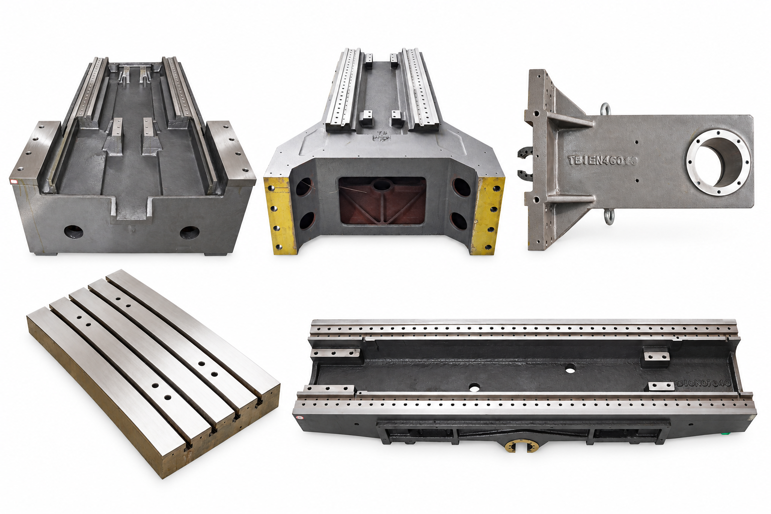
Identify the Existing Assembly
Send the supplier photos of the machine nameplate, component nameplate, connectors, and mounting points. Include the full model suffix, serial number, control version, and any available drawing revision. If a technician has diagnosed the fault, attach that report and the exact alarm text.
Ask for the current replacement part number and any required adapter, cable, or parameter changes. If the supplier cannot confirm a direct replacement, treat the purchase as an engineering change rather than a routine spare-part order.
Check the Interfaces That Matter
| Assembly | Details to Confirm | Evidence to Request |
|---|---|---|
| Spindle | Mounting register, bolt pattern, gauge-line position, tool interface, speed range, torque, drive arrangement, orientation feedback, lubrication, and cooling | Dimensioned drawing, operating limits, drive requirements, and serial-number-linked test report |
| Ball screw | Diameter, lead, travel, end machining, nut mounting, preload, accuracy specification, and support bearings | Approved assembly drawing and inspection report identifying the measured error |
| Servo motor and drive | Approved motor–drive pairing, current ratings, torque–speed curve, feedback interface, connector pinout, brake, and control support | Manufacturer pairing reference, wiring diagram, and supported firmware versions |
| Tool-clamping assembly | Gripper geometry, thread, pull-stud specification, release travel, and required clamping force | Matching part reference, installation drawing, and clamping-force test procedure |
| Hydraulic fixture | Mounting, operating pressure, clamping force, stroke, port threads, seals, and control sequence | Fixture drawing, hydraulic circuit, and rated operating conditions |
For a BT spindle pull claw, specify more than BT30, BT40, or BT50. The mating thread and pull-stud geometry also need to match the spindle’s clamping mechanism.
A hydraulic clamping system needs a separate pressure and force check. Matching the mounting holes does not establish that the fixture can hold the workpiece under the planned cutting load.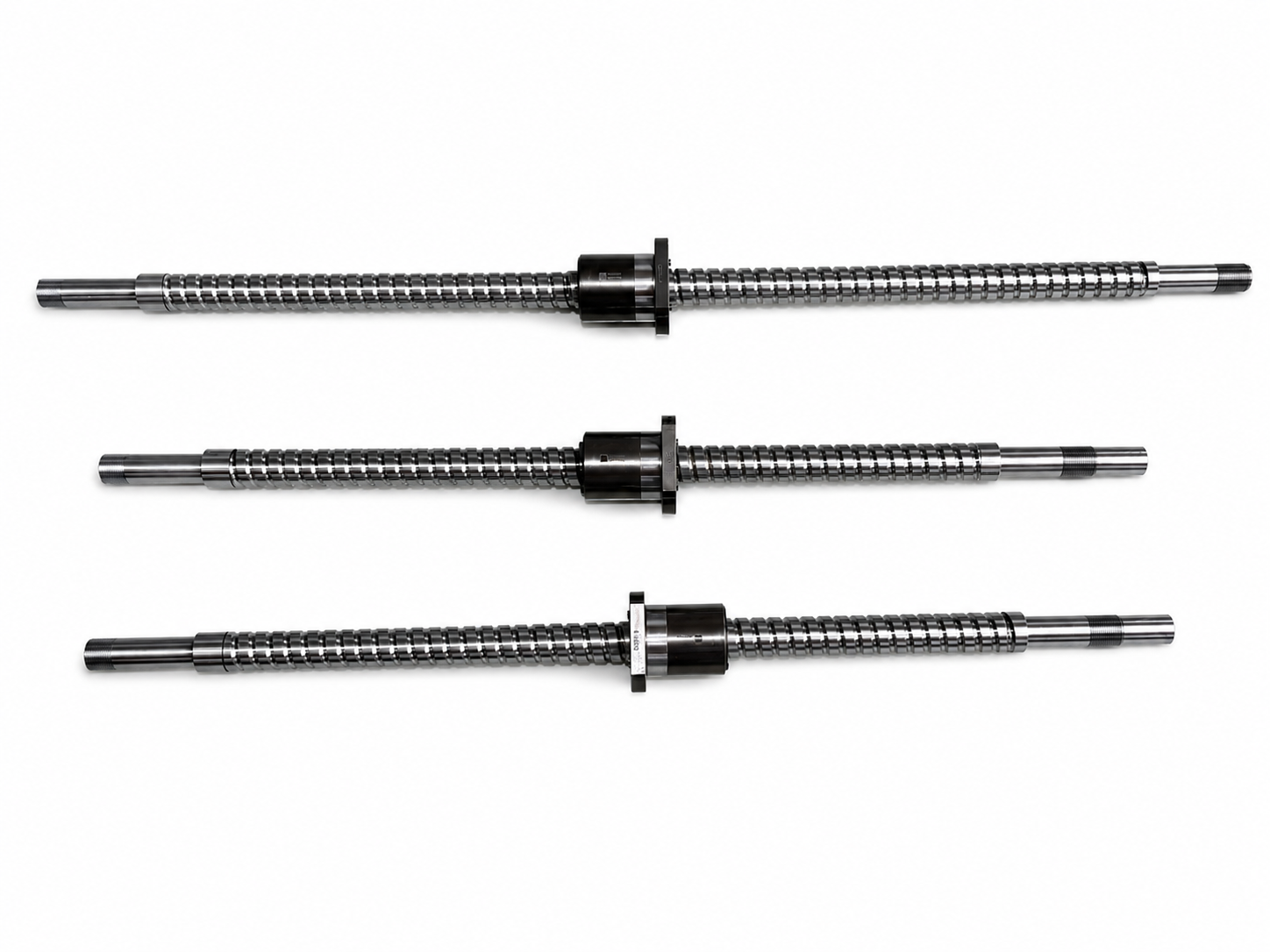
Catch Mismatches Before Payment
Ball-Screw Lead
Consider a proposed replacement with the same 32 mm diameter as the old screw, but a 10 mm lead instead of 5 mm. At the same screw speed of 1,000 rpm, theoretical travel changes from 5,000 to 10,000 mm/min. That is a 2:1 change, not a minor dimensional difference.
This is an illustrative calculation, not a customer case. Such a change requires an engineering review of axis scaling, motor speed and torque, travel limits, and feedback configuration. Matching diameter alone would miss it.
Motor and Drive Ratings
Two motors marked 750 W can have different rated speeds, torque, feedback, brakes, and mounting dimensions. Request the approved motor–drive pairing instead of choosing a drive by wattage alone.
Also separate the machine’s incoming supply from the component’s required supply. A machine connected to 380 V may contain other voltage circuits. The relevant checks are the drive input, motor compatibility, and auxiliary power requirements.
Control Support
A shared communication protocol does not establish compatibility. For an EtherCAT replacement, confirm that the controller supports the specific device, its communication configuration, required operating modes, synchronization, and firmware. Encoder resolution is only one item in that review.
Before changing control hardware, back up the existing parameters and PLC program. Assign responsibility for restoring tool-change, clamping, lubrication, and safety-related functions.
Choose the Supply Route
| Route | Best Fit | Condition Before Ordering |
|---|---|---|
| Machine builder or authorized channel | Serial-number-specific parts, supported replacements, and machines under warranty | Confirm the current part number and whether the replacement needs additional hardware or software |
| Independent replacement supplier | Alternative assemblies with documented interface and performance matches | Obtain a written comparison showing matches, differences, and required changes |
| Repair, rebuild, or custom manufacture | Discontinued or damaged assemblies without a supported replacement | Agree on inspection findings, approved drawings, replaced items, and final test criteria |
Compare quotes on the same scope. A bare spindle cartridge is not equivalent to a package containing a motor, encoder, cables, and cooling equipment. Ask each supplier to state what is included, what will be reused, and what must be purchased separately.
Use the quoted dispatch date, shipping time, and commissioning scope to estimate downtime. There is no reliable universal price discount or lead time for “compatible CNC parts.”
Put the Requirements in the Order
Send the same request to two or three suitable suppliers. Use these fields to make their replies comparable:
- Machine: manufacturer, model, serial number, and control version.
- Existing component: complete part number, nameplate photos, drawing, and diagnosed fault.
- Replacement scope: assembly, cables, connectors, bearings, adapters, and other included items.
- Compatibility: written replacement reference and a list of required changes.
- Testing: measured characteristics, test conditions, instruments, and agreed limits.
- Delivery and support: dispatch date, packaging, installation responsibility, and commissioning support.
- Commercial terms: payment stages, warranty coverage, inspection period, and responsibility for a documented mismatch.
For a critical assembly, tie payment milestones to agreed evidence or acceptance stages where commercially available. An upfront-payment requirement alone does not establish whether a supplier is reliable; traceability, inspection access, and enforceable order terms matter too.
Specify Measurable Acceptance Tests
“Runout below 0.01 mm” is incomplete without a measurement location and method. A report should identify the spindle surface or test bar, distance from the spindle nose, instrument, and machine condition. For ball screws, name the accuracy standard and error characteristic rather than recording only “C5.”
Give each test an agreed limit before shipment. Keep the assembly serial number, dated photographs, drawing revision, and inspection results together. A video can show the operating sequence, but it cannot replace the measurements needed to verify accuracy.
Inspect and Commission Safely
On arrival, compare the order, nameplate, packing list, and approved drawing. Photograph transport damage and check connectors, mounting surfaces, corrosion protection, and missing accessories before installation.
Authorized personnel should isolate hazardous energy before servicing and verify the isolation. Stored electrical, pneumatic, hydraulic, and mechanical energy must also be addressed. In U.S. workplaces, OSHA’s lockout/tagout standard sets requirements for hazardous-energy control during applicable servicing and maintenance.[1]
Follow the assembly manufacturer’s installation, lubrication, cooling, tightening, and run-in instructions. Do not apply a generic bolt torque, starting speed, temperature limit, or empty-run duration to every assembly.
Commissioning should cover the affected functions: axis direction and travel limits, spindle orientation, tool retention and release, auxiliary sequences, and safety devices. Guards must protect against hazards such as rotating parts and flying chips; OSHA addresses these in its general machine-guarding requirements.[2]
Use the agreed test part or machine-performance checks for final acceptance. Record the material, tooling, operating conditions, and measurement results. A successful no-load run does not establish cutting accuracy.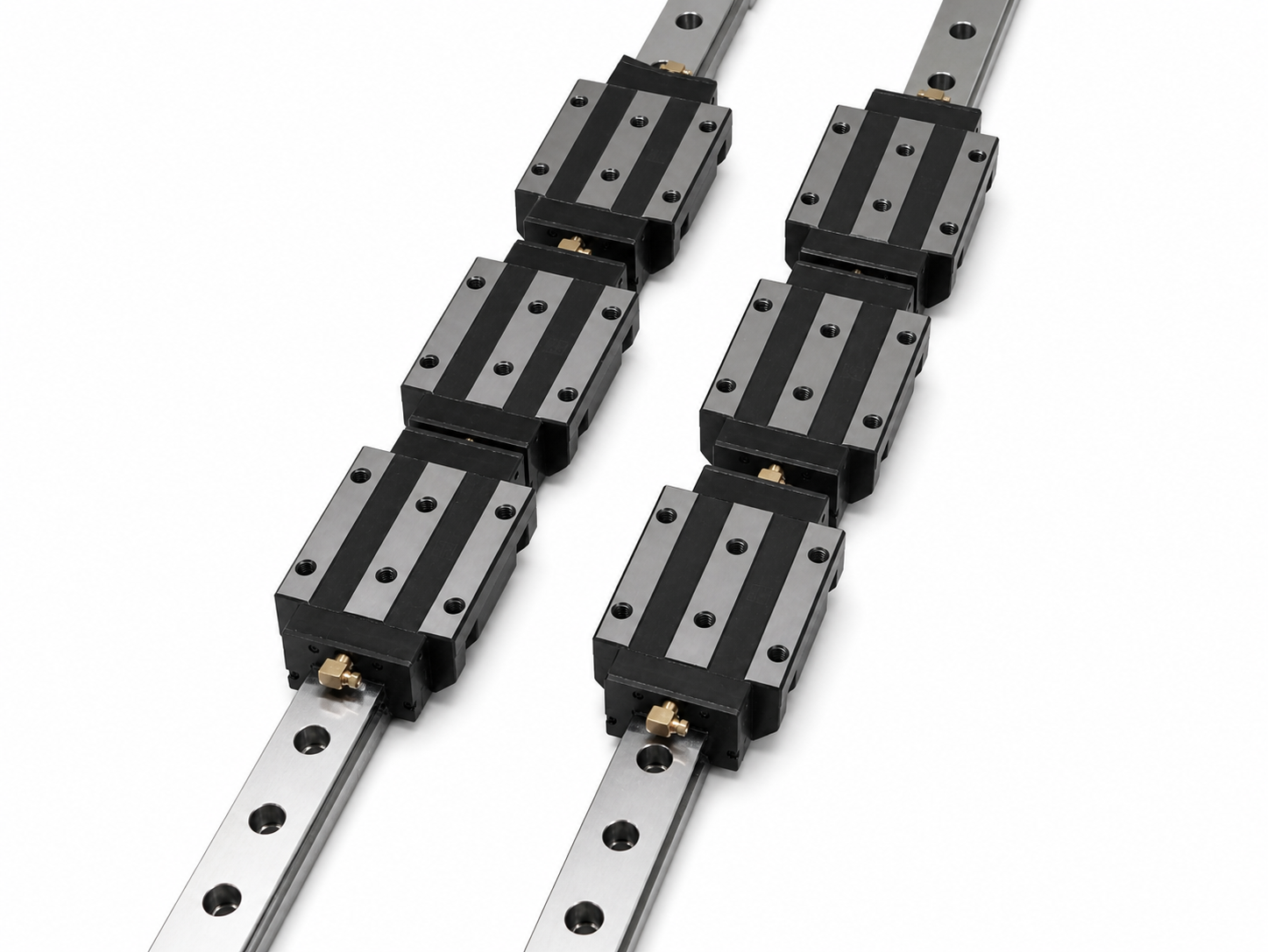
Keep the removed assembly until the replacement has passed acceptance and any return obligations are settled. Save the final parameter backup, test report, and replacement part number in the machine’s maintenance record.
Discontinued and Used Assemblies
What If the Original Part Is Discontinued?
Ask the machine builder for a superseding part number first. If none exists, have a qualified specialist document the mounting, functional requirements, interfaces, and operating limits before approving a custom replacement. A worn part can provide dimensions, but it does not reveal every original tolerance or performance requirement.
Can a Used Assembly Meet Precision Requirements?
Possibly, but a running video and claimed operating hours are not enough. Require tests relevant to the application, such as runout, axial play, positioning performance, or operation under load. Obtain a written inspection or return period. If the seller cannot demonstrate the required performance, price the item as an unverified repair candidate rather than a production-ready replacement.