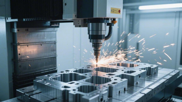
Of course—VMCs are at the heart of cavity machining. With a 20,000 rpm spindle, a single setup is enough to precision-mill complex surfaces.
Nanometer-level interpolation can bring surface roughness down to Ra 0.4 μm, while repeat positioning accuracy remains stable at 0.003 mm.
This eliminates alignment error, keeps core insert fitting clearance within 0.01 mm, and enables one-stop production through high spindle speed and precise control.
Machining Mold Cavities
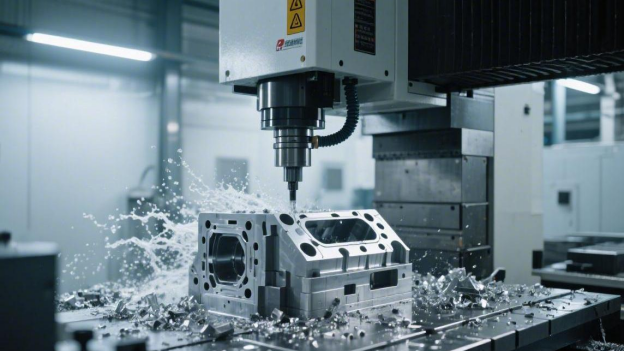
Roughing
When you clamp a block of P20 steel with a hardness of around HRC 32 onto the table, or face a piece of H13 mold steel fresh back from heat treatment at nearly HRC 54, the moment the first cut goes in, the machine sound tells the truth. If the spindle load meter swings more than 15%, your depth of cut or feed rate is already pushing the VMC beyond its comfort zone.
That steady, heavy metallic pounding means the 50 mm face mill is tearing through steel at a cutting speed of 800 m/min. Experienced machinists often ignore the screen and watch the chip color instead. Dark blue chips mean more than 80% of the cutting heat is being carried away, and that is exactly where you want to be.
When machining large cavities deeper than 150 mm, never chase speed by pushing depth too hard. On a typical BT40 spindle machine, keeping each cut to 5% to 8% of the tool diameter is what protects long-term machine accuracy. If you force the cut depth beyond 2.5 mm, high-frequency spindle chatter will travel straight through the ball screws. That will not only destroy an insert worth RMB 120, but also eat into the machine’s accuracy reserve for the next five years.
· Dynamic milling: Forget the traditional 70% step-over. Try reducing radial engagement to about 10%.
· Feed compensation: With a high step-over strategy, feed can jump from F800 to F3200/min or even higher.
· Temperature control: When machining hardened mold steel, 6 bar high-pressure air blast is often more effective than water cooling.
· Protecting the cutting edge: Repeated hot-cold cycling creates microscopic cracks in carbide—often the first sign of edge chipping.
· Residual stock control: After roughing, any step height left behind must stay below 0.25 mm, or it will cause serious trouble later.
Modern CAM systems now automatically slow the tool before it enters a 90-degree corner. What used to rely entirely on the operator’s instinct on the override switch is now handled by the software, which keeps the tool engagement angle locked below 30 degrees. The benefit is obvious: a 16 mm bull-nose cutter can keep cutting S136 mold steel continuously for 160 minutes without needing an insert change or inspection stop.
That machine-gun cutting sound usually means a high-feed mill is at work. These tools have a very small lead angle, typically around 10 degrees, which cleverly redirects cutting force upward instead of sideways. That force travels straight up the spindle, making the machine more stable at high speed. So when you see feed rate climb to 5500 mm/min, do not assume the process is reckless—this is physics helping suppress vibration.
1. Coating standard: For materials above HRC 48, AlTiN coating is mandatory. Its protective layer activates only at around 850°C.
2. Tool overhang ratio: Never let tool extension exceed 3 times the diameter, or lateral deflection can easily reach 0.06 mm.
3. Helical entry: Stop plunging straight into steel. A 2-degree ramp or helical entry can add years to spindle bearing life.
4. Through-tool coolant pressure: In deep-cavity machining, internal coolant above 35 bar is essential—it clears chips from the cavity floor instantly.
When machining cavities as deep as 200 mm, chip build-up at the bottom becomes an invisible killer. If you are still relying on a thin external coolant nozzle, chips will be crushed and recut again and again. Every recut can spike edge temperature by more than 100°C. Once that kind of useless internal heat accumulation starts, even the best AlTiN coating on the market will not save your inserts.
Using a 30 mm cutter for bulk removal and then jumping directly to an 8 mm finishing tool to clean the corners is like asking an embroidery needle to do a rock drill’s job. The smarter solution is to add an intermediate step with a 14 mm or 16 mm tool to remove any leftover stock above 1.2 mm in the corners.
Semi-Finishing
If you send a finishing tool straight into 0.5 mm of uneven rough stock, the moment it strikes those inconsistent steps, the resulting 20-micron vibration will ruin surface finish.
Experienced operators first check the cavity corners with calipers to see how much stock the roughing tool actually left behind. If more than 0.8 mm remains in an R5 corner, do not rush into a large step-over path. Switch to a 12 mm bull-nose cutter, raise spindle speed to 4500 rpm, and run a pass at 2200 mm/min. That will even out the stock to a much more manageable 0.15 mm.
When semi-finishing 718H mold steel at HRC 42, the depth of cut is usually locked at 0.25 mm. That number keeps the toolholder from yielding under high-speed rotation. Once chip load starts fluctuating, the tool begins to bend microscopically. Even a deviation of just 0.01 mm will show up later as ugly ripples during finishing.
| Material Type | Recommended Hardness (HRC) | Tool Diameter (mm) | Step-over | Remaining Stock (mm) |
| P20 Mold Steel | 28–34 | 10 (ball nose) | 0.35–0.50 | 0.12 |
| H13 Hot-Work Steel | 48–52 | 8 (ball nose) | 0.20–0.30 | 0.10 |
| S136 Stainless Steel | 50–54 | 6 (bull nose) | 0.15–0.25 | 0.08 |
| NAK80 Pre-Hardened Steel | 38–42 | 12 (ball nose) | 0.40–0.60 | 0.15 |
For narrow-slot cavities as deep as 80 mm, once the tool’s length-to-diameter ratio exceeds 4:1, semi-finishing should switch to a constant-Z strategy. Let the tool peel away that 0.3 mm of leftover stock layer by layer, like peeling an onion.
At that stage, chip evacuation is no longer about “flushing out” chips but about “blowing clean.” Even a tiny 0.1 mm chip caught in the toolpath, driven by a 6000 rpm spindle, can scratch a deep groove into the cavity wall like a grinding wheel.
If the machine has no through-tool coolant, turn the air compressor up to at least 0.6 MPa and aim the blast directly at the cutting edge. The machining zone must be completely free of recutting debris. When the rotating holder produces a light whistle, that usually means cutting force is distributed evenly. That kind of stability comes from keeping radial engagement around 10%.
· Overcut detection: Before running the program, collision simulation should be accurate to 0.005 mm.
· Toolholder selection: Ditch cheap ER collets and switch to shrink-fit holders—runout can be held below 3 microns.
· Compensation setting: To account for tool wear, compensation is usually set 0.02 mm higher than the theoretical value.
· Corner slowdown: When entering corners smaller than R3, manually reduce feed override to 60%.
When machining NAK80, semi-finishing is best done with a contour-following path. That keeps cutting resistance constant, and spindle load fluctuation should be held within 3%.
If the chips come off in a pale earthy yellow, cutting-zone temperature is sitting around 400°C, which is ideal for TiAlN-coated tools. If the chips show no color at all, feed is too low and the edge is rubbing rather than cutting. That kind of dry rubbing can collapse the cutting edge after just 3000 mm of travel.
Even with feed set at F2500, coolant concentration still needs checking with a refractometer. If flood coolant is used, concentration must stay above 8%, or lubrication will not be sufficient. After machining a large cavity, it is best to let the workpiece sit on the machine for 20 minutes to release residual thermal stress. Before finishing, sweep the datum surface with a dial indicator. If deviation exceeds 0.01 mm, it must be re-indicated.
The deeper the cavity, the harder it is to control elastic tool deflection. On the final semi-finishing passes, try adding one extra spring pass—run the exact same path again without changing any parameters. That can shave off the last few microns left behind by elastic recovery. It is especially effective on hardened materials above HRC 50.
Many people overlook holder balance, but once spindle speed exceeds 8000 rpm, G2.5 balance quality is standard. If holder imbalance is too high, cavity walls will show a fish-scale texture. That finish is a nightmare for polishing technicians—even a full afternoon with a #1500 oil stone may not remove it. After semi-finishing, the part size should land very close to the upper side of tolerance, around +0.1 mm.
Finishing
Once semi-finishing leaves behind a uniform 0.12 mm skin across the cavity, the real battle begins. At this point, the VMC is no longer a metal-eating beast—it becomes more like an embroiderer dancing at 2-micron precision. If you want a mirror finish on S136 mold steel, spindle speed usually needs to go beyond 15,000 rpm, paired with a 6 mm high-precision ball-nose cutter.
That faint, leaf-nibbling cutting sound means the tool tip is tracing curves at 3500 mm/min. Experienced machinists will place a hand on the safety door to feel the vibration. If the frequency feels irregular, then either BT40 spindle balance or the tool’s 2-micron runout tolerance has drifted—and that can destroy the results of the next 48 hours of continuous machining.
Finishing is not about speed. It is about stability. In a workshop held at 20°C, if spindle thermal growth reaches 0.01 mm, the cavity floor can end up with an unrecoverable step. That is why experienced operators let the spindle idle for 30 minutes before cutting, until thermal equilibrium is reached.
When setting step-over, cusp height is usually controlled at around 0.003 mm. With an R3 ball-nose cutter, line spacing should not exceed 0.05 mm. If you widen it to 0.1 mm for convenience, visible scallop marks will appear on the cavity surface, and the polishing team will spend an entire shift removing them with stones.
· Cutting speed control: When machining quenched material at HRC 52, surface speed should stay within 120–180 m/min to prevent premature edge wear.
· Compensation strategy: Since the tool will wear by several microns, tool diameter should be remeasured every 5000 meters of toolpath.
· Surface finish: To achieve Ra 0.4, feed override is generally locked at 100% and should not be adjusted mid-process.
· Toolpath overlap: Transition overlap is set at 0.5 mm to avoid visible witness lines between adjacent paths.
When finishing cavity walls as deep as 120 mm, tool deflection is impossible to ignore. A long-reach ball-nose cutter with an 8:1 length-to-diameter ratio is required, but spindle speed should actually drop to around 8000 rpm to stay away from resonance. By adjusting the software’s constant-Z finishing strategy, lateral pressure can be kept stable and deflection can be compressed into a tolerance band of 0.005 mm.
If the refractometer shows coolant concentration below 5%, too much water will cause microscopic rust spots on materials like NAK80. The ideal range is 10% to 12%, which keeps the tool edge wrapped in a thin lubricating film and carries away the final less than 10% of remaining heat.
· Start-end blending: Use a spiral lead-out where toolpaths meet at the cavity floor so the cutter does not leave a navel-shaped mark when retracting.
· Temperature monitoring: Without temperature control in the workshop, the temperature rise from 8:00 a.m. to 12:00 noon can expand a large mold base by 0.02 mm.
· Holder rigidity: Sintered shrink-fit holders are preferred; their clamping force is 3 times that of conventional spring collets and concentricity is far better.
· Corner cleanup: After finishing with a large ball cutter, switch to an R0.5 or even smaller ball tool for rest machining and progressively clean out the remaining stock in the corners.
Many apprentices want to finish a complex cavity in one uninterrupted pass. In reality, sectioned finishing is safer. Cut the upper 50 mm first, then change to a fresh tool before moving deeper. That keeps wear consistent across the entire cavity surface and prevents the top from ending up wider than the bottom.
At this stage, machining allowance is essentially gone. Even with the finest dial indicator, needle movement should remain locked within 0.01 mm.
For ultra-hard materials above HRC 58, conventional carbide tools are already at their limit. At that point, CBN (cubic boron nitride) tools become an option. Their wear resistance is more than 20 times that of standard coated tools. Even though a single cutter may cost around RMB 800, it can run for 72 hours without replacement and maintain cavity consistency throughout.
· Path smoothing: Enable arc interpolation in the software to reduce fragmented G01 line segments and keep machine motion smoother.
· Acceleration control: The machine’s look-ahead function must be enabled, predicting at least 500 program blocks in advance to avoid excessive deceleration at corners.
· Tool inspection: Before every tool change, inspect the edge under a microscope. Even a 0.01 mm micro-chip is enough reason to scrap the tool.
The final obstacle in precision cavity machining is often the tiny vent grooves. These slots are only 0.015 mm to 0.02 mm deep, and direct machining demands exceptional micro-displacement response from the machine. Skilled operators use micron-level edge finders to ensure positional error on each vent groove stays within 0.005 mm.
Mold Bases
Three Core Advantages
By fully exploiting the capabilities of a 3-axis or 4-axis machine, mold base machining reveals three irreplaceable strengths.
Since mold plates such as A plates and B plates are usually wide rectangular components, often 500 mm × 600 mm or larger, the VMC’s vertical spindle turns gravity into an ally. The workpiece lies flat on the table, and that natural horizontal support eliminates the 0.02 mm-level sag deformation that long plate parts can suffer under their own weight.
· Balanced force transmission: Cutting force travels vertically down into the machine base. Compared with the lateral load path of an HMC, a VMC can handle heavier S50C template plates without introducing about 0.01 mm of axial drift.
· Stable clamping: With a standard 150 mm × 150 mm magnetic chuck array, total holding force can exceed 3000 kg, keeping plate movement within 0.005 mm even during roughing at 3 mm depth of cut.
· Simple alignment: Using a 3D edge finder to pick up X-Y on a flat plane gives single-point repeat positioning accuracy of 0.003 mm, greatly reducing setup time for 400 mm-class plates.
This layout lets the operator directly observe a tiny 0.1 mm cut as the tool contacts the steel surface. More importantly, when machining plates thicker than 100 mm, it ensures the clamping force and guideway support act together in the vertical direction, locking in flatness.
The most frustrating part of mold base machining is multi-hole alignment. When A and B plates must close precisely, guide pillar hole positional tolerance has to be held within 0.01 mm. Completing drilling, reaming, and boring in one setup on a VMC is the best way to eliminate cumulative error.
· Coordinate consistency: With the G54 coordinate system rigidly locked, positional error from the first 12 mm guide pillar hole to the final 30 mm pocket stays within 0.008 mm.
· Tool-change efficiency: A 24-tool magazine can switch tools in 2 seconds, moving seamlessly from a 50 mm face mill to a 10 mm drill and eliminating the 0.015 mm alignment tolerance that repeated setups introduce.
· Backlash control: Backlash on a VMC over a 500 mm travel is usually compensated to 0.005 mm, allowing the fit clearance between guide pillar and bushing—typically 0.015 mm to 0.025 mm—to remain exceptionally smooth.
This highly integrated machining logic means that when a fine boring head cuts the guide pillar bore wall at 80 m/min, roundness and perpendicularity already have a rigid geometric relationship to the datum surface, completely avoiding datum contamination or bump damage from inter-process handling.
The complex cooling channels inside a mold base are where a VMC’s deep-hole capability really shows. When machining waterline holes deeper than 200 mm, the through-spindle coolant (TSC) system pumps coolant directly to the cutting edge at 20 bar. That is not just cooling—it is forcefully driving chips away from the hole bottom.
· Smooth chip evacuation: Using a G83 peck drilling cycle, with the first peck set to 3 times the drill diameter and through-spindle coolant engaged, prevents recutting chips from enlarging the hole by 0.05 mm.
· Longer tool life: In P20 steel (HRC 30–32), drilling 10 continuous 12 mm deep holes keeps tool-tip temperature below 80°C, preventing the hardened layer that dry cutting can create.
· Accuracy protection: If deep-hole drill runout is kept within 0.01 mm, positional deviation can still stay within 0.1 mm even at 200 mm depth, avoiding interference with ejector pin holes.
Three Key Processes
When machining a 400 mm × 500 mm S50C mold plate, an experienced machinist never rushes to hit cycle start. As a 50 mm face mill enters the cut at 800 rpm, feed per tooth needs to stay at 0.15 mm. A spindle load reading around 65% is ideal. If it climbs higher, subtle chatter from a BT40 spindle will leave 0.02 mm waviness on the plate surface.
Flatness tolerance on a mold base is usually held within 0.015 mm, which is a direct test of VMC bed rigidity. When machining 100 mm thick P20 pre-hardened steel, stress release can bow the plate by 0.03 mm to 0.05 mm. Skilled machinists rough both sides first, leaving 0.5 mm stock per side, then loosen the clamps and let the steel “breathe” before finishing.
| Machining Stage | Cutting Speed (m/min) | Feed per Tooth (mm) | Depth of Cut per Pass (mm) | Target Roughness (Ra) |
| Rough Face Milling | 120–150 | 0.18–0.25 | 1.5–2.5 | 3.2–6.3 |
| Semi-Finish Milling | 160–180 | 0.10–0.12 | 0.3–0.5 | 1.6–3.2 |
| Finish Face Milling | 200–240 | 0.05–0.08 | 0.05–0.1 | 0.4–0.8 |
As the cutting edge glides across the steel surface, the chips should come off in a light bluish-purple. If they turn black, local temperature has already exceeded 600°C, and the P20 surface will begin to form a secondary hardened layer.
Once the faces are flat, the drill has to go into the body of the plate to open up the cooling channels. A 12 mm deep-hole drill running to 200 mm depth on a VMC absolutely requires 20 bar through-spindle coolant. If pressure is insufficient, chips will be recut inside the hole, and hole diameter error can grow from 0.05 mm to 0.15 mm.
· In a G83 peck cycle, the first peck depth should be set to 3 times the drill diameter, with each subsequent peck reduced by a factor of 0.8.
· Deep-hole drill runout must stay within 0.01 mm, or positional deviation can reach 0.1 mm after 100 mm depth.
· Coolant concentration should be maintained at 8% to 10% to provide enough lubrication to remove friction heat from deep inside the hole.
· Reduce feed by 50% before the drill exits the hole to prevent edge chipping or excessive exit burrs that could affect later mold closing.
If scratches are left inside the waterline because of poor chip evacuation, long-term cooling cycles can create stress concentration, and after 100,000 molding cycles the plate may even crack.
Once the cooling channels are complete, half the soul of the plate is already there. Next comes the most critical feature of all: the guide pillar bores that determine closing accuracy. To meet an H7 fit, drilling must leave 0.25 mm stock per side for finish boring. A 32 mm fine boring head running at 450 rpm and 35 mm/min feed should produce chips that fall away like fine silver threads.
Bore accuracy usually has to stay within 0.008 mm—it is the lifeline that determines whether the A and B plates can close smoothly on the injection molding machine. During measurement, the inside micrometer must be recalibrated once every hour, because a 5°C shop temperature swing can easily erase a 0.01 mm tolerance. The Ra 0.6 finish required in every guide bush hole exists to ensure even force during bushing press-fit.
| Hole Type | Dimensional Tolerance (mm) | Positional Requirement (mm) | Surface Finish (Ra) | Recommended Tool |
| Guide Pillar / Guide Bush Hole | +0.010 / -0 | Within 0.01 | 0.6 | Carbide fine boring tool |
| Ejector Pin Hole | +0.02 / -0 | Within 0.02 | 1.6 | Step carbide reamer |
| Counterbored Bolt Hole | +0.2 / -0 | 0.1 is sufficient | 6.3 | Welded core drill |
| Cooling Waterline Hole | +0.15 / -0 | Within 0.2 | 3.2 | Internal coolant drill |
Using different parameters for different hole functions is how a VMC delivers maximum efficiency. When machining harder materials like 718H, boring speed should be reduced further to 60 m/min. Higher speed can trigger 0.005 mm-level micro-vibration, leaving visible chatter marks on the bore wall.
The real devil is often hiding in something as simple as pocket milling. For a pocket 30 mm deep, using a 20 mm end mill to slot it in one go makes bottom corner accuracy very hard to control. The better solution is step-down milling at 2.5 mm per layer with feed at 1200 mm/min, then switching to a long-neck, short-flute cleanup tool for corner finishing.
During corner cleanup, radial engagement should not exceed 0.1 mm. That is what keeps pocket wall perpendicularity within 0.01 mm. For pockets designed to receive precision cavity inserts, sidewall finish of Ra 0.8 is standard. Watch the coolant flow carefully and make sure it reaches the exact 1 mm² zone where tool edge meets metal.
Single-Setup Work
Reducing Cumulative Error
In the roar of a mold shop, as you watch that BT40 spindle hold steady at 12,000 rpm, the real fear is rarely tool breakage. It is the possibility that the workpiece might shift by even 5 microns inside the vise—too small to see, but more than enough to ruin precision work.
Once that kind of movement happens, the G54 coordinate system you spent hours establishing is effectively gone. In precision mold manufacturing, positional drift caused by a second setup is one of the most common sources of disaster.
Even with repeated dial-indicator correction, a standard 6-inch precision vise can hardly keep bottom-face parallelism within 0.01 mm after the part is unclamped and re-clamped. That is enough to leave visible mismatch in what should have been a perfectly fitting mold cavity.
When a mold requires fitting clearance as tight as 0.005 mm, every unnecessary removal makes error snowball. In the end, the parting line can be left with 0.02 mm of flash that can never truly be corrected.
· Thermal displacement compensation: After the spindle runs at high speed for 4 hours, thermal growth on the Z-axis often reaches 15 mm. Only by keeping the part fixed can the control system compensate automatically.
· Repeat tool-setting error: A manual tool setter has its own 0.003 mm mechanical dead zone, and once backlash is added, second tool setting can double the error instantly.
· Clamping-force deformation: Tightening with 15 Nm can cause thin mold plates to flex elastically. Once unclamped and clamped again, the original flat datum is gone.
· Radial tool runout: The 0.01 mm runout of an ER32 collet is a fixed offset in a single setup, but becomes an unpredictable random variable after re-clamping.
A VMC’s C3-grade ball screw has pitch error compensation built into the control system at the factory. As long as the workpiece never moves on the table, the positional relationship among the X, Y, and Z axes stays locked to the machine’s geometric accuracy.
If you flip the part just to machine the bottom side, the 0.002 mm resolution once monitored by linear scales instantly degrades into a setup dependent on the operator’s feel and dial-indicator reading. In mold manufacturing, that is a technical step backward.
For narrow cavities up to 40 mm deep, going from roughing to finishing in one setup keeps every toolpath within the same coordinate DNA.
That continuity ensures the stock left for ball-nose cleanup remains highly uniform—usually a steady 0.05 mm—so tool loading stays stable and avoids elastic deflection marks caused by sudden cutting-force changes.
· Datum lock: Using the mold base datum corner as the global reference keeps concentricity error across more than 20 cavity holes below 0.008 mm.
· Surface consistency: For 3D contour milling, keeping the machine running without shutdown or unclamping helps hold surface roughness steadily at Ra 0.4 with a high-gloss finish.
· Self-balancing of stress: It cuts non-cutting wait time by 30% and prevents the part from naturally deforming by 0.015 mm outside the machine because of temperature change.
· In-machine automatic alignment: Use an infrared probe to inspect once every hour.
Many veteran machinists still like to remove a part after roughing for manual stress relief. But for pre-hardened steels like P20, finishing the job directly on the VMC often works better because the machine’s rigidity physically restrains the material’s micro-creep.
With the workpiece locked to the table, the heavy cast-iron bed acts like a massive heat sink and support frame. That forced physical constraint is often the most effective way to control dimensional drift in complex cavities.
Test data shows that over a continuous 12-hour machining cycle, mold plates processed in a single setup have diagonal positional error more than 65% lower than those machined in multiple stages.
This is especially critical when machining micro pin holes in precision connector molds. Once the workpiece is unclamped even once, cylindricity is almost impossible to hold to 0.005 mm. Complete one-pass machining, by contrast, can push yield close to 100%.
· Micro step-over: During finish milling, radial step-over is fixed at 0.02 mm, so cutting heat exits with the chips instead of transferring into the part.
· Shrink-fit holder support: Tool runout is held to an extreme of 0.003 mm, minimizing lateral cutting force at high spindle speeds.
· Fully integrated programming: Drilling, tapping, milling, and reaming are all written into a single master program, forcing the machine’s built-in tool-life logic to be used properly.
Watching the coordinates keep changing on the VMC screen while the workpiece remains rock-solid underneath—that sense of process certainty is one of the strongest weapons we have against uncertainty in metal machining.
For unattended 24-hour single-machine operation, every human intervention removed from the process cuts off one more path by which 0.01 mm error can creep in, bringing precision back under the control of mathematics and physics.

Advantages and Limitations
A cast-steel machine bed weighing over 5 tons sits solidly on the shop floor, with spindle speed holding at 10,000 rpm. Standing at the control panel and watching coolant flood behind the enclosure door, you quickly realize that Single-Setup is not just about convenience.
If you unclamp a 400 mm × 500 mm P20 mold plate to machine the bottom, then bring it back and re-establish the datum edge, even a skilled operator will lose at least 15 minutes to tapping and re-indicating.
That labor loss from repeated setup and removal often accounts for 30% to 45% of the cost structure in precision mold work. In a single-setup process, the automatic tool changer can switch between roughing and finishing tools in just 1.5 seconds, compressing auxiliary downtime into scraps.
· Repeatability fully utilized: As long as the part never moves, the machine’s 0.003 mm repeat positioning relative to G54 remains the foundation of hole-position accuracy.
· Immune to handling damage: It avoids random scratches of about 0.05 mm caused by repeatedly moving heavy and expensive steel blocks weighing up to 100 kg.
· Surface texture consistency: Continuous cutting helps maintain Ra 0.8 or better, without the discontinuities caused by thermal expansion and contraction during shutdowns.
· Lower tool damage: With a constant cutting-force angle, entry is smoother, and tests show this reduces edge-chipping risk by 15%.
In precision machining, time is often the enemy of accuracy. Every extra minute the workpiece remains fixed on the machine is another layer of protection. For every 1°C fluctuation in ambient temperature, metal components can undergo micron-level stress displacement internally.
Even though a 3-axis VMC is powerful, it has one unavoidable limitation: without flipping the part, it can never machine the sixth bottom face in one go.
The spindle points vertically downward, so when machining deep side holes or complicated lateral chamfers, long tool overhang causes chatter and cuts machining rigidity by 40% almost instantly.
If cavity depth exceeds 150 mm, the Z-axis travel and toolholder diameter create serious collision risk. That physical limit means single-setup machining has to yield when facing ultra-deep molds.
After 12 hours of continuous cutting, heat from the high-speed spindle can conduct through the column and cause 0.01 mm to 0.02 mm of thermal drift in Z. In a long one-shot process, that drift is difficult to detect by eye.
· Clamping dead zone: Standard vise jaws are about 40 mm high, and the area they grip becomes a complete machining no-go zone in that program, requiring secondary operations later.
· Chip evacuation limits: In blind cavities 50 mm deep, chips cannot fall away under gravity. Even 0.6 MPa center coolant may still allow recutting wear.
· Compounded risk: If a 20-hour program fails at the tapping stage in the final minutes, every precision operation before it may be lost.
· Spring-back hazard: Thin-wall mold parts under clamping force above 10 kN can spring back by 0.015 mm the moment the clamp is released, causing dimensional oversize.
To extend the working window of a single setup, high-level shops often equip the VMC with a magazine holding 24 tools or more. They use a “redundant tool” strategy: after a finishing cutter has run for 300 minutes, the system automatically loads an identical backup tool.
When machining quenched material above HRC 50, that automatic changeover can hold surface tolerance within 0.008 mm. The process no longer requires constant operator attention, and the machine can run unattended for 48 hours.
The real experts calculate the effective cutting distance of every tool before they even write the program. They are willing to let the machine cut through the night because every toolpath has already been planned to avoid fixtures and clamps by at least the 5 mm safety line.
To break through the side-machining barrier of a 3-axis VMC, many shop owners add a fourth axis with 360-degree rotary capability. A complex mold base that once required the part to be flipped five times can then be completed in a single setup simply by indexing the rotary axis.
The upfront investment is higher, but when machining molds with 4 side sliders, the process time can drop to one-third of the original, with efficiency up by 200%.
Measured with a dial indicator, hole-position deviation on a rotary axis is usually around 0.01 mm, while manual flip-and-indicate setups by even an experienced machinist often fluctuate around 0.03 mm.
For plates thicker than 50 mm, side process lugs can be used for suspended clamping, allowing precision milling of all four sides and all top-side cavity features in one uninterrupted cycle.
· Hardened positioning: Use high-precision locating pins hardened to HRC 58 to reduce re-clamping shift from the thread level down to the micron level.
· Stock control: Leave exactly 0.1 mm stock before finishing and pair it with 3000 mm/min feed to minimize cutting-force influence on part position.
· Simulation-based avoidance: Run a full 100% collision simulation before cutting. A single setup leaves no room for even 0.5 mm of interference error.
Watching coordinate values move in 0.001 mm increments on the screen, you can feel how much control the process gives you. That control is one of the strongest tools we have against uncertainty in metal machining.
Advanced Efficiency Techniques
Standing in front of an extrusion die component hardened to HRC 52, an experienced process engineer will often leave a 3 mm to 5 mm “process handle” on the bottom face. This keeps the part suspended in a single setup and frees up five faces for machining, avoiding the hassle of repeatedly repositioning clamps.
When spindle speed climbs to 15,000 rpm, the workpiece becomes extremely sensitive to clamping conditions. High-precision soft jaws made from 45 steel, tightened with a torque wrench to 35 Nm, can keep workpiece movement below 0.002 mm even under heavy cutting.
· Leave a clamping lug: Keep 4 mm of stock at the bottom for strong clamping so the top face and four side faces remain in one coordinate system.
· Graduated clamping force: Use 45 Nm during roughing, then release and re-clamp at 20 Nm before finishing to release 80% of the internal stress.
· Soft-jaw machining: Bore a fresh set of soft jaws on the machine before each job; circular runout can be kept within 0.005 mm.
· Stress release: After removing large stock volumes, stop the machine for 20 minutes and let the metal spring back naturally before running the final 0.01 mm finish-milling program.
The infrared probe acts like a sensitive feeler, touching the datum bore wall automatically every 60 minutes to detect thermal expansion caused by cutting heat.
The moment the control algorithm sees Z-axis thermal growth reach the warning threshold of 0.007 mm, a G10 command updates the coordinate compensation instantly. This closed-loop feedback keeps cavity depth tolerance within 0.01 mm over a continuous 12-hour run.
But coordinates alone are not enough. If that 10 mm finishing cutter develops even a tiny chip mid-process, all prior effort is wasted. High-output VMC shops equip every finishing tool with a “twin brother” and set an 80% expected-life warning in the control.
When the laser tool setter detects wear exceeding 0.015 mm, the ATC arm swaps in a fresh tool within 1.8 seconds and resumes the remaining path. That prevents the mold parting line from developing a 0.02 mm step caused by tool wear.
| Evaluation Item | Traditional Scattered Workflow | Expert-Level Single Setup | Data Difference |
| Positioning Method | Manual dial-indicator alignment | Automatic probing cycle | 85% efficiency improvement |
| Repeat Accuracy | 0.02–0.05 mm | 0.003–0.005 mm | 10× better accuracy |
| Tool Connection | Manual tool setting after each change | Laser non-contact measurement | Error controlled within 2 mm |
| Non-Cutting Time | 40% of total cycle | Only 7% of total cycle | Pure machining time doubled |
For precision mold work, shop air conditioning is often forced to hold at 22 ± 0.5°C, while an oil chiller keeps spindle bearing temperature within ambient +2°C.
To pursue even better surface quality in a single setup, radial depth of cut (Ae) during finish milling is usually kept at around 2% of tool diameter. Paired with feed at 4500 mm/min, that allows about 90% of cutting heat to leave instantly with the chips.
“In mold making, the real masters are not the ones who can re-clamp fastest, but the ones who can keep the workpiece rooted on the machine the longest. As long as the steel does not move and ambient temperature stays within 1°C, those few microns never leave your control.”
Using shrink-fit holders to hold radial runout to an extreme of 0.003 mm is the secret to preventing chatter marks in narrow-slot mold machining. That allows every flute of a four-flute ball-end cutter to share cutting load evenly, improving surface finish to a mirror-like Ra 0.2.
When machining long, narrow cavities deeper than 100 mm, a trochoidal cutting strategy keeps lateral force constant throughout the path. That prevents the workpiece from shifting in the fixture by the 10 microns that can otherwise be triggered by sudden force spikes.
· Constant load: Tool engagement angle is always kept below 30 degrees, and spindle load fluctuation stays within 5%.
· Through-tool coolant: Pressure remains above 1.2 MPa to flush out chips from the bottom of 50 mm deep holes.
· Layered progression: Each step-down is fixed at 1.5 times the tool diameter so the full flute length participates and wear remains even.
· Interference simulation: Before running the program, use a 3D avoidance algorithm to check holder-to-part clearance and keep at least 2 mm of safety margin.