Rigidity & Cutting Power
VMC
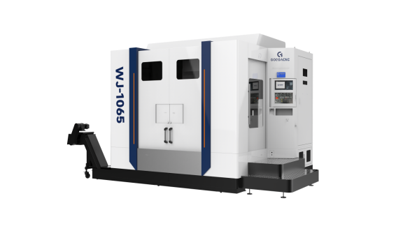
Walk into a typical neighborhood machine shop, and you will probably see a VMC850 taking up about 6 square meters. This machine is a 5.5-ton block of iron, with a base cast entirely from HT300-grade rigid cast iron. It stands firmly on six heavy iron feet fitted with rubber pads for vibration damping.
The spindle does the real cutting work, and the way it grips the tool has a direct impact on whether the cutter will deflect under load. Inside the spindle is a tapered bore available in several size classes, and the load-bearing characteristics vary significantly from one to another.
· BT30 toolholder: weighs only about 0.5 kg, can reach 24,000 rpm, and is mainly used for aluminum parts such as phone housings.
· BT40 toolholder: the most common shop standard, typically used with 8 to 16 mm carbide cutters for machining 45 steel blocks.
· BT50 toolholder: a heavy unit weighing over 3 kg, locked at both ends for maximum rigidity and intended for heavy-duty cutting.
An operator brings over a block of P20 mold steel measuring 400 mm long, 300 mm wide, and 150 mm thick, and clamps it firmly to the table. To hollow out the bottom of the block, the machine’s “neck”—the Z-axis—has to extend downward by more than 300 mm.
The farther the toolholding structure extends, the more top-heavy and unstable the setup becomes. At that point, if the machine switches to a 63 mm face mill for aggressive cutting, the spindle load meter can jump to 85%, close to an overload alarm.
The deeper the cutter enters the material, the greater the backward force transmitted into the machine column. That is why the internal rib structure of the column matters so much. Machine builders often cast internal ribs in an “A” pattern or a grid pattern, with wall thickness on one side increased to more than 45 mm.
The guideway system carrying the heavy workpiece back and forth is another critical area. It must move smoothly, but it also has to absorb the shock generated at the moment the cutting edge strikes the material.
· Ball linear guides: use rows of small steel balls and can travel up to 48 meters per minute, making them suitable for lighter, faster machining.
· Roller linear guides: use cylindrical rollers, carry about 30% more load, and resist deformation better under pressure.
· Box ways: metal slides against low-friction material, hand-scraped during assembly, and deliver the best impact resistance for heavy cutting.
On machines equipped with box ways, experienced operators may allow the cutter to engage up to 60% of its width. On machines with ball-guide rails, they usually limit engagement to 30% and reduce feed from 1,200 mm/min to 800 mm/min.
Every chip that comes off even slightly thicker than expected adds stress to the four rows of cylindrical bearings at the spindle nose. When the cutter advances only 0.08 mm per revolution, you hear a low, muffled hum. The cutting force travels up through the toolholder and column before finally being absorbed by the machine’s 300 mm-thick cast structure.
A slight increase in shop temperature can upset a machine that was perfectly calibrated at the factory. A rise of just 2°C will cause a 600 mm ballscrew to grow by 0.012 mm. As the screw expands, the original preload is reduced, and the machine may begin to vibrate at higher speeds.
If the workpiece is not supported evenly, even a 5-ton machine cannot deliver stable cutting. How the part is clamped to the table has a direct impact on final surface quality.
· Hydraulic machine vise: can generate 4,000 kg of clamping force, leaving the workpiece no room to move.
· Zero-point quick-change chuck: uses a pull-stud system with 20 kN of holding force and repeatability within 5 microns.
· Bolt-and-strap clamp setup: uses M16 high-strength studs to secure irregularly shaped workpieces at multiple points.
Programmers also play an important role by avoiding toolpaths that force the cutter straight into the material. Instead, they use circular interpolation and gradually enter the cut, keeping the engaged contact arc below 45 degrees. That greatly reduces the impact load on the machine.

HMC
Step into a shop machining large diesel engine castings, and a horizontal machining center with dual pallets can easily occupy 15 square meters. The inverted T-shaped cast base alone can weigh as much as 8 tons.
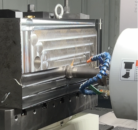
Its spindle is mounted horizontally, so the cutter drives straight into the side of the workpiece. Behind the spindle housing is a massive cast-iron wall more than 400 mm thick.
When the cutter is pushing against the workpiece at full force, the entire reaction load is transmitted into that 400 mm-thick cast wall. Instead of a slender belt drive, this spindle is backed by a gearbox filled with large gears.
In low gear, the spindle speed may drop to 300 rpm, but the motor can still deliver 1,200 N·m of torque. With a 100 mm indexable cutter installed, it can strip away 8 mm of titanium alloy in a single pass.
The freshly cut chips can reach nearly 600°C, but because the spindle is horizontal, they fall directly downward into the chip trough beneath the machine. By the time the cutter comes around again, it is always engaging a clean surface.
Try that same operation on a vertical machine while plunging into a deep pocket, and the hot chips collect at the bottom with nowhere to go. The cutter ends up re-cutting them repeatedly, and the impact can snap a 16 mm carbide shank on the spot.
The rotary table supporting the workpiece is built like a solid mechanical lock. Beneath the square table are two toothed discs, each with a full circle of 360 serrations.
Once the table reaches the programmed angle, a hydraulic cylinder clamps the two discs together with 5 tons of force. Even under heavy side cutting, angular displacement at the table can be held within 0.003 degrees.
Experienced maintenance technicians often say that under heavy cutting, you can judge chassis stability just by listening to the sound. Shops have documented the difference when two machines cut the same hard alloy under similar conditions:
| Machine Type | Material | Cutter | Depth of Cut | Feed Rate | Machine Load | What the Operator Hears |
| Vertical cutting | Grade 718 superalloy | 50 mm face mill | 1.5 mm | 400 mm/min | 85% (needle fluctuating) | Sharp screaming with tearing metallic noise |
| Horizontal cutting | Grade 718 superalloy | 50 mm face mill | 4.0 mm | 650 mm/min | 60% (needle steady) | Low, heavy rumble like an old tractor under load |
As the logbook shows, the horizontal machine was cutting nearly three times as deep, yet the spindle load remained steady at 60%. The current running through the wall-mounted three-phase power cable also held flat at 45 amps.
Nearby, a robot arm thicker than a person’s thigh picks up a 15 kg boring tool with a 400 mm-long bar. As soon as the heavy tool enters the spindle, a 120 mm-diameter face flange locks it in place with a clean, airtight fit.
The several-ton cast assemblies moving along the X, Y, and Z axes are all supported by roller guideways 65 mm wide. For every meter the structure travels, the four bearing blocks roll over more than 400 solid steel rollers.
When the control program reaches the roughing operation, three large nozzles flood the tool tip with coolant at 30 kg/cm². Amid the spray, the machine’s chain-type conveyor carries away 20 kg of metal scrap per minute.
Several tons of cast iron accelerate back and forth inside the enclosure, and even the eight M24 anchor bolts embedded in the concrete foundation can be felt vibrating slightly. Yet when the operator places a dial indicator against the casting, the needle stays steady within 0.01 mm.
Outside the enclosure is a 2 m by 1.5 m pallet changer. A worker using a torque wrench stands on the foot pedal platform and tightens fasteners on a 300 kg cast pump housing.
It may take 20 minutes to tighten twelve M16 high-strength bolts on the outside station. But as soon as the cutter inside finishes, the pallet changer rotates 180 degrees in just 15 seconds, bringing the next workpiece directly into the cutting zone.
The Z-axis ballscrew driving the spindle forward is a massive threaded shaft 50 mm in diameter. The servo motor behind it delivers more than 20,000 N of thrust, forcing the cutter deep into hard cast housings.
To withstand that load, the spindle nose is packed with four sets of angular contact bearings with outer diameters up to 130 mm. The bearings are densely arranged and kept alive by a thin lubrication tube that drips two drops of dedicated oil every five minutes.
After one full heavy roughing cycle, the operator runs a surface roughness probe across the machined face. The display reads Ra 1.6. To the touch, the freshly machined alloy surface feels almost as smooth as household glass.
Part Size & Complexity
Flat & Plate-Type Parts
Walk into a subcontract machining shop and you will often see large metal plates on the floor, two or three meters long and weighing several hundred kilograms. For these broad steel or aluminum plates that are only 20 to 30 mm thick, operators usually go straight to a vertical machining center. The cutter comes down from above like a drill, while the cast table moves the part in X and Y.
A 1.2 m by 0.6 m aerospace aluminum plate is too heavy to move by hand. An overhead crane operator lowers a chain and hook, lifts the plate, and places it squarely on the machine table. With that weight resting on the table, it is usually enough to secure it using step blocks and T-bolts.
There are several common ways to fixture flat plates on a vertical machine:
· Vacuum pads for 3 mm-thick sheet metal
· Magnetic chucks for 45 steel plates
· 50 mm flat clamps for smaller round metal discs
· Angled side clamps that hold the part along all four edges
Once the part is fixed, the machine typically loads an 80 mm or 120 mm face mill. Several carbide inserts spin at 3,000 rpm and sweep across the broad metal surface like a mower. Each pass removes 2 mm, while hot chips strike the surrounding metal enclosure like rain.
The maximum plate size depends on the machine’s travel. Take the common VF-4 as an example: it travels up to 1,270 mm in X and 508 mm in Y. As long as the plate is under 500 mm wide, even if it is as long as 1.5 meters, an operator can machine it in two setups with both ends extending beyond the table.
The thinner the plate, the more difficult it becomes. Take a 5 mm-thick heat sink panel for a telecom base station. As soon as the cutter starts removing material, internal stresses can cause the panel to curl upward like a potato chip. The operator has to slow the feed to 500 mm/min and limit each pass to less than 0.2 mm, then flip the panel and machine the other side immediately.
Mounting a 1 m² steel plate weighing 200 kg vertically on the side of a horizontal machine is extremely risky. The operator has to work off the side of the machine and manage a heavy suspended mass that could shift or fall under vibration.
The C-frame layout of a vertical machine also limits usable vertical space. From the spindle nose to the table surface, many machines have only 600 to 700 mm of clearance. Subtract a 150 mm deep-hole drill and a 100 mm vise, and the remaining part height is often under 400 mm.
Every day, shops produce flat parts of all kinds:
· Plastic mold bases drilled with dense arrays of M6 holes
· 15 mm-thick custom machine mounting plates
· Hydraulic cover plates with O-ring grooves
· Aerospace titanium brackets pocketed to remove 70% of their weight
· Semiconductor vacuum panels with mirror-like surface finishes
Standing outside the machine door, the operator can see the entire 1-meter-wide table at roughly a 45-degree angle just by lowering their head slightly. If a tapping tool starts pulling out a string of swarf while cutting M8 threads, it is immediately visible. The operator can simply blow out the chips from a 30 mm-deep hole with an air gun. Touching off the edge of the workpiece with a dial indicator is equally convenient.
Flat panels often require hundreds or even thousands of small holes. Coolant is delivered through six small lines beside the tool at 20 kg pressure and sprayed directly onto the aluminum plate. Fine chips do not stay on a flat table for long; they slide down the sloped side covers and are gradually carried out by the chip conveyor into a blue bin about waist-high.
When machining a transparent acrylic test plate measuring 800 by 800 mm, spindle speed may need to reach 12,000 rpm. The operator installs a 1.5 mm single-flute cutter to machine a dense pattern of fine grooves. If the table is tilted by even 0.02 mm, groove depth will vary noticeably.
A senior electrician with grease on his hands wipes off a worn 12 mm end mill and drops it into the scrap bin. A freshly machined aluminum plate is lifted away by the crane, while a stack of unopened 6061 aluminum plates waits on a wooden pallet nearby. The tower light on the machine turns green, and the spindle comes down again to pick up the next start point.
Large Parts, Box-Type Parts & Multi-Face Components
When dealing with a 400 kg tractor gearbox housing, operators do not choose a machine that cuts from above. For large, blocky castings, the standard choice is a horizontal machine that cuts from the side.
An overhead crane operator lifts an engine housing over a meter tall and places it against a square tombstone fixture at the center of the pallet. The spindle extends horizontally from the side like a rifle held level. Dozens of heavy bolts pin the raw casting firmly to the vertical fixture face.
The biggest problem with large castings is repeated lifting and repositioning. That is why these machines use a rotary base. At the press of a button, a 400 kg workpiece can rotate 90 degrees smoothly on its own. The spindle may finish boring three holes on the left face, each spaced 150 mm apart, and then the table rotates so it can immediately machine four flat faces on the right side.
Some pump housings are close to 800 mm in length, width, and height. On older machines, they barely fit and may even prevent the front door from closing. Move the same part to a heavy-duty machine with a 1 m by 1 m pallet, and there is still 200 mm of free space around it, giving inspection probes plenty of room to enter and exit without interference.
To fixture irregular castings securely, shops may spend more than RMB 80,000 on a custom hydraulic fixture set. The base connects to four high-pressure hydraulic lines, and the pump delivers 15 MPa of clamping force. Even when the cutter hits from the side at full load, a workpiece weighing several hundred kilograms will not shift.
Before machining begins, the work coordinate system must be established accurately. The machine uses a touch probe with a ruby ball tip and lightly touches three points on the surface of the casting. The screen updates instantly and calculates any misalignment within milliseconds, then compensates automatically.
When machining hard 42CrMo alloy steel, the machine switches to a spindle as thick as a person’s thigh. A large cutter body fitted with twelve ceramic inserts runs at 800 rpm while roughing the surface. Once the cut is underway, red-hot sparks can fly more than two meters.
Deep-hole drilling in automotive chassis parts with a 400 mm-long drill creates major chip evacuation problems. In vertical drilling, chips collect at the bottom of the hole and quickly jam the drill. With horizontal drilling, the hot chips fall out of the hole under their own weight.
Meanwhile, 80 liters of coolant per minute are blasted from the side, flushing the inside of the hollow casting clean. A magnetic chip conveyor below can remove 50 kg of chips per hour, eliminating the need for workers to dig debris out of blind cavities by hand with steel hooks.
In production shops, heavy box-type parts that require machining on multiple faces typically follow well-defined machining specs:
| Application | Material | Weight / Size | Machining Requirement |
| V8 engine housing | Gray cast iron | About 180 kg | Cavity machining and finishing on four side faces |
| Industrial pump housing | Ductile iron | About 600 mm across | Machining three large mating faces |
| Spherical bearing housing | Alloy steel | Nearly 500 mm tall | Through-holes on opposite faces with strict alignment |
| Heavy gearbox housing | HT250 cast iron | About 450 kg | Six-face facing, drilling, and tapping |
If two aligned holes must be drilled on opposite faces 600 mm apart, and center deviation must stay below 0.02 mm, manual re-fixturing is not realistic. With an automatically indexing pallet, the machine can complete both holes in one setup and keep alignment error within 0.015 mm.
To machine a perfect bore 250 mm in diameter and 300 mm deep, the operator installs a heavy boring bar fitted with a vibration damper. A small diamond insert is used to skim the internal wall at very low speed. The finished surface comes out polished enough to reflect a face.
Complex parts often require 70 or 80 different tools. On the side of the machine is a tool magazine that looks like an oversized revolver, holding up to 120 tools ranging from M3 taps to 200 mm roughing tools. A robotic arm handles the changes, and tool-to-tool time can be as short as 2.5 seconds.
In batch production of valve bodies and pipe fittings, stopping the machine to reload parts wastes too much time. Large horizontal machines often come with dual automatic pallet changers. While one 200 kg workpiece is being machined behind the door, the operator loads the next one on the outside station using a pneumatic wrench.
The chips produced by heavy roughing are thick and hard. The chip conveyor motor must therefore be rated at 1.5 kW or higher. Its toothed steel belt climbs upward slowly and can discharge over 50 kg of scrap per hour into a blue collection bin outside the machine.
When installing a machine that costs hundreds of thousands, shops usually excavate a pit more than 1 meter deep. It is then filled with high-strength concrete and pre-embedded with six 30 mm anchor bolts. Even when the machine is aggressively roughing heavy steel castings, a cup of water placed nearby will not show a ripple.
Large machines weighing 4 to 5 tons also expand and contract with shop temperature. That is why cooling oil is circulated through the machine at a constant 22°C. Even in summer, when ambient temperature reaches 38°C, the machine can still hold a 50 mm bore consistently after ten continuous hours of operation.
Shop Fit
Footprint
If you compare machine catalogs, two machines with the same 1-meter machining capacity can require completely different amounts of floor space. A typical 1060 vertical machining center is about 2.8 meters long and 2.2 meters wide.
In actual shop layout, around 7 square meters is enough for that machine to run normally. But if you switch to a horizontal machine with the same 1-meter travel and a 630 mm dual-pallet system, the situation changes completely.
The base of the horizontal machine may be 5.5 meters long and 3.8 meters wide, consuming more than 20 square meters of floor space. A vertical machine works from above, with the spindle and column positioned behind the table, giving it a tall, narrow C-shaped profile.
A horizontal machine cuts from the side and generates much higher thrust, so the base has to be built as a broad, heavy T-shaped structure. And beyond the cast base itself, there is also a full ring of very space-consuming auxiliary equipment around it.
· Chain-type tool magazine: about 1.5 m² on its own
· Two rotary pallet stations: extending about 2 meters outward
· 600-liter coolant tank: usually placed at the rear or side
· Separate hydraulic and temperature-control units: about 0.5 m²
Vertical machines usually use a compact carousel tool magazine with 24 tools mounted halfway up the column, so it does not take extra floor space. Horizontal machines handling more complex work typically require a separate tool cabinet holding 60 or even 120 tools.
That large tool magazine is about the size of a household wardrobe and stands beside the machine. When workers load face mills weighing several kilograms, they also need enough room to turn and lift their arms comfortably.
If you calculate floor space using only the machine’s nominal dimensions, you will come up short. Maintenance and parts replacement require access space. The electrical cabinet at the rear may have a door that swings open 800 mm, and there must be enough room for a technician to stand there and work.
If two machines are placed too close together, an electrician may not even be able to open a multimeter properly during troubleshooting. Vertical machines are much easier to arrange, and multiple units can be lined up neatly along a wall.
A 500 mm gap between vertical machines is usually enough for a person to pass sideways. A 1-meter aisle in front of the machine is sufficient for loading parts, setting tools, and cleaning chips.
A horizontal machine is different. It is a large unit that needs access from all sides. Maintenance on the spindle may require access from the front or even from above. Pallet changes happen at the front, while tool loading may require walking around to the rear.
Even the way chips are removed each day affects aisle planning. Vertical machines cutting aluminum do not generate large volumes of chips, so a 200-liter cart parked at the front-right corner is usually enough to collect them.
Horizontal machines are built for tougher materials and can generate piles of steel chips or cast iron fines every hour. They usually need dual augers and a chain conveyor to lift chips to a height of 1.2 meters.
From there, the chips are dumped into a 500-liter rolling hopper positioned behind the machine.
· Front aisle for VMC: 1.5 m, enough for a pallet jack
· Side clearance for VMC: 0.5 m, enough for one person
· Front area for HMC: 3.0 m, enough for forklift loading
· Rear clearance for HMC: 2.5 m, needed for chip hopper access
Another detail that inexperienced buyers often miss is that some machine elements extend outward during operation. On a horizontal machine, when the spindle retracts during a tool change, the rear sheet-metal cover can move backward by as much as 400 mm.
If the machine was installed too close to the wall, that rear cover will hit the concrete and dent immediately. On a vertical machine, when the table moves outward, an operator standing 500 mm away is still safe with a natural half-step back.
The spacing between building columns can also create layout problems for horizontal machines. In modern industrial buildings, columns are often spaced 8 or 12 meters apart.
If a 5.5-meter-long HMC is placed between two columns 8 meters apart, there may not even be 2 meters left for an AGV or material cart to pass. In that same 8-meter bay, three VMCs each 2.8 meters long can often fit without feeling crowded.

Height Clearance
Many buyers look at a 1060 vertical machining center and see a listed machine height of 2.8 meters. But that is only the static height when the machine is idle. During actual operation, things change. When the spindle rises to the top of the Z-axis for a tool change, the highest point of the machine can exceed 3.2 meters.
If your crane beam is only 3.5 meters above the floor, that becomes a problem. The plastic cable carrier and oil lines above the spindle can also bounce up and down by another 150 mm during motion. That thick hose bundle can keep striking the steel beam until the internal cables wear through. If the building clear height is below 4.2 meters, installing a mid-size VMC becomes very restrictive.
· VMC 850: 2.6 m high at rest, 2.95 m during operation
· VMC 1060: 2.8 m high at rest, 3.3 m during operation
· Motor maintenance clearance: at least 500 mm above the machine
· Recommended building height: ideally 4.5 m or more
Many owners assume a 5-meter-high shop will be fine, but what really matters is crane hook height. On a 5-ton overhead crane, the lowest hook position is often only 3.8 to 4.0 meters above the floor. If you need to lift a 500 mm-tall mold into the machine, usable space becomes tight very quickly. The slings and hook assembly alone may consume nearly 800 mm of vertical space.
| Machine Type | Static Height (m) | Max Operating Height (m) | Minimum Hook Height (m) | Door Clearance (m) |
| Standard VMC 850 | 2.6 | 2.95 | 3.8 | 2.8 |
| Heavy-duty VMC 1060 | 2.8 | 3.3 | 4.5 | 3.0 |
| HMC 630 | 3.1 | 3.1 | 4.2 | 3.2 |
| 5-axis VMC | 3.4 | 3.9 | 5.2 | 3.5 |
At that point, you realize the floor-to-bottom height of the mold plus the mold itself is already approaching 4.5 meters. If your crane hook tops out at 4.2 meters, those few hundred millimeters become the deciding line. A new machine may be sitting on the floor, but heavier parts still cannot be loaded into it. Then you are forced to look for ultra-short rigging gear, or even remove the leveling pads beneath the machine base.
In terms of height, horizontal machining centers are often easier to manage. Because the spindle moves horizontally, the machine’s total height does not change even when the Z-axis is fully extended. A 630-pallet HMC is typically fixed at around 3.1 meters high. For older plants with ceilings only 4 meters high, that can be a major advantage.
However, the fans and oil mist filtration units on top of the machine can still be an issue. To keep the spindle and electrical cabinet from overheating, an HMC usually needs three or four high-power exhaust fans on top. If the machine is too close to the ceiling, heat cannot dissipate properly and the top temperature can climb above 45°C. In summer, the machine may alarm repeatedly from overheating, forcing you to climb a ladder and cool it manually.
· Top ventilation gap: at least 800 mm for airflow
· Oil mist duct bend radius: at least 300 mm
· Motor removal clearance: 1 meter above the machine
· Lighting clearance: lamps should be at least 1.5 meters above the machine roof
If the roller shutter door at the shop entrance is only 3.2 meters high, the machine may not fit through it while on a truck. A 1260 VMC loaded on a flatbed can already sit about 1.1 meters above the ground, pushing total transport height past 4 meters.
The upper Z-axis servo motor is usually removed first. Taking off that motor can reduce total height by about 400 mm, but it creates a lot of follow-up work. Wiring has to be reconnected, parameters reset, and the manufacturer’s technician may need to realign the mechanical home position.
· Standard flatbed height: typically 0.9 to 1.2 m above ground
· Low-bed trailer height: 0.5 to 0.7 m above ground, but more expensive
· VMC with motor removed: overall height can often drop to around 2.5 m
· Entrance ramp: if the doorway is sloped, the top of the machine will sweep a larger arc while entering
To reduce vibration, HMCs often require a pit about 500 mm deep filled with reinforced concrete. VMCs, by contrast, usually stand directly on the shop floor and are supported by a few large leveling bolts. Once adjusted, those bolts raise the machine base by more than 100 mm, almost like putting it on high heels.
That means operators have to lift parts higher every day when loading the machine. If a worker is 1.7 meters tall and the table height approaches 1.2 meters, lifting a 25 kg casting into place puts much more strain on the lower back. To improve ergonomics, some shops end up welding on a non-slip platform about 500 mm wide.
· Platform width: should not be less than 600 mm
· Anti-slip tread depth: at least 3 mm so it remains safe with cutting oil present
· Handrail: if the platform is high, a 1.1 m railing may be required by code
· Sunken installation: some factories simply lower the floor by 300 mm and recess the machine
If you plan to add automation later, insufficient ceiling height will become a serious regret. When a robot arm swings a heavy part through the air, its working radius can be very large. If you want to install a floor-track robot for a VMC, you should ideally have at least 5 meters of clear height. Otherwise, the robot can easily strike overhead lighting during movement.
Foundation & Load Capacity
A standard 1060 vertical machining center, including sheet metal and a fully loaded tool magazine, typically weighs between 5.5 and 7.5 tons. In most factories, a 200 mm-thick concrete slab can handle that load as long as the subgrade is solid. But for a 630 horizontal machining center with a similar travel range, the bare machine alone can weigh 15 tons, and with a dual-pallet system it can reach 22 tons. Concentrated over less than 15 square meters, that means a floor load of at least 8 tons per square meter.
Typical workshop slabs are usually designed for only 2 to 3 tons per square meter, which is nowhere near enough for an HMC of this class. If you place a horizontal machine directly on an old floor and hope for the best, small foundation settlement is likely within three months. Even if the base shifts by only 0.05 mm, that may translate into 0.02 mm of spindle error, enough to ruin every part produced.
· VMC anchor bolts: usually 6 to 8, evenly distributed around the machine base
· Required floor capacity for VMC: at least 3.5 tons/m², otherwise the base may deform
· Leveling check: bolts should be retightened after the first month and again after the third month
· Vibration-damping pads: VMCs often use thick rubber leveling pads under the feet
Many factories skip proper foundations to save money. Then the punch press next door starts up, and every part from the VMC comes out with fine chatter marks.
For an HMC, you usually need to excavate a pit 1,000 to 1,200 mm deep and build a dense reinforced cage inside it. The pit should extend beyond the machine footprint on all sides, with 50 mm-thick foam isolation panels around the perimeter.
· Pit depth: 1 meter recommended for a 630 machine to prevent deeper soil from loosening under thermal change
· Rebar size: 14 mm rebar arranged in a 200 mm grid both ways
· Concrete grade: C30 or C35 high-strength concrete is required to avoid cracking after curing
· Reserved anchor pockets: leave 150 mm square openings for secondary grouting after machine placement
· Moisture barrier: lay 0.2 mm PE film at the bottom to keep groundwater from rising and rusting the cast structure
Concrete needs the full 28 days to cure. Even one day less can leave micro-cracks that only appear later.
If you rush production and the moisture has not fully dissipated, the foundation may continue to deform after leveling as the water evaporates. Veteran technicians often say it is better to leave the machine outside in the sun for another month than to push it into an uncured pit. Expanding additives may shorten curing by a few days, but on a machine worth several million, those days are not worth saving.
An HMC may have 12 to 16 leveling bolts, making alignment several times more difficult than on a VMC. If the load on those bolts is uneven, the machine can twist slightly as several-ton castings move across the structure. When the machine accelerates and stops at 60 meters per minute, the inertial forces are enormous. If the foundation does not hold it firmly, the entire machine will shift, and tool life can drop by more than 30%.
· Dynamic deviation: spindle tilt during motion must stay within 0.02 mm
· Curing temperature: ideally 15°C to 25°C to prevent temperature-induced cracking
· Grouting material: use non-shrink high-strength grout with very high flowability for secondary filling
The impact generated when the automatic tool changer handles a heavy toolholder weighing over 10 kg can travel a surprisingly long distance through the floor. Vibrations in the 50 to 100 Hz range are enough to ruin the mirror finish on a precision grinder nearby. The ideal solution is to keep at least 2 meters between machine foundation pits and fill the gap with dry sand or gravel to dissipate the energy.